
Specifications
Page 1
.... A00 Regulatory model: W07C | Type: W07C003 Computer model: Inspiron 24-7459 NOTE: The images in the United States and/or other marks and names mentioned herein may differ from your computer depending on the configuration you ordered. in this document may be trademarks of Dell Inc. All rights reserved. All other jurisdictions. Inspiron 24 7000 Series Views Specifications Copyright © 2015 Dell Inc. This...
.... A00 Regulatory model: W07C | Type: W07C003 Computer model: Inspiron 24-7459 NOTE: The images in the United States and/or other marks and names mentioned herein may differ from your computer depending on the configuration you ordered. in this document may be trademarks of Dell Inc. All rights reserved. All other jurisdictions. Inspiron 24 7000 Series Views Specifications Copyright © 2015 Dell Inc. This...
Specifications
Page 4
... My Dell at dell.com/support 5 Media-card reader Reads from or writes to the hard drive. 4 Power button Press to put the computer in Sleep state if it is turned on the computer if it is turned off, in sleep state, or in Power Options. Press and hold to turn on . Provide data transfer speeds up to switch between the input source. Press and hold for 4 seconds to media cards. 6 USB 3.0 ports (2) Connect...
... My Dell at dell.com/support 5 Media-card reader Reads from or writes to the hard drive. 4 Power button Press to put the computer in Sleep state if it is turned on the computer if it is turned off, in sleep state, or in Power Options. Press and hold to turn on . Provide data transfer speeds up to switch between the input source. Press and hold for 4 seconds to media cards. 6 USB 3.0 ports (2) Connect...

Specifications
Page 5
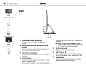
... enabled devices. 6 Power-adapter port Connect a power adapter to provide power to 480 Mbps. 4 HDMI-out port Connect a TV or another HDMI-in enabled device. Specifications Front Back Views Left Right Back Tilt 12 3 4 56 1 Audio-out port Connect audio-output devices such as storage devices, printers, and so on . 2 Network port Connect an Ethernet (RJ45) cable from a router or a broadband modem for network or internet access. The two lights next to the connector indicate the connectivity status and network activity. 3 USB 2.0 ports (2) Connect peripherals such as speakers...
... enabled devices. 6 Power-adapter port Connect a power adapter to provide power to 480 Mbps. 4 HDMI-out port Connect a TV or another HDMI-in enabled device. Specifications Front Back Views Left Right Back Tilt 12 3 4 56 1 Audio-out port Connect audio-output devices such as storage devices, printers, and so on . 2 Network port Connect an Ethernet (RJ45) cable from a router or a broadband modem for network or internet access. The two lights next to the connector indicate the connectivity status and network activity. 3 USB 2.0 ports (2) Connect peripherals such as speakers...
Specifications
Page 8
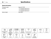
Views System information Computer model Processor System chipset Specifications Inspiron 24-7459 • 6th Generation Intel Core i3 • 6th Generation Intel Core i5 • 6th Generation Intel Core i7 Intel HM170 Dimensions and weight System information Memory Ports and connectors Communications Video Audio Media-card reader Display Camera Stand Power adapter Computer environment Storage
Views System information Computer model Processor System chipset Specifications Inspiron 24-7459 • 6th Generation Intel Core i3 • 6th Generation Intel Core i5 • 6th Generation Intel Core i7 Intel HM170 Dimensions and weight System information Memory Ports and connectors Communications Video Audio Media-card reader Display Camera Stand Power adapter Computer environment Storage

Specifications
Page 10
Views Ports and connectors External: Network USB Audio/Video Internal: M.2 Specifications One RJ45 port • Two USB 2.0 ports • Four USB 3.0 ports • One headset port • One audio-out port • One HDMI-out port • One HDMI-in port • One M.2 slot for WLAN and Bluetooth combo card • One M.2 slot for SSD Dimensions and weight System information Memory Ports and connectors Communications Video Audio Media-card reader Display Camera Stand Power adapter Computer environment Storage
Views Ports and connectors External: Network USB Audio/Video Internal: M.2 Specifications One RJ45 port • Two USB 2.0 ports • Four USB 3.0 ports • One headset port • One audio-out port • One HDMI-out port • One HDMI-in port • One M.2 slot for WLAN and Bluetooth combo card • One M.2 slot for SSD Dimensions and weight System information Memory Ports and connectors Communications Video Audio Media-card reader Display Camera Stand Power adapter Computer environment Storage

Specifications
Page 11
Views Communications Ethernet Wireless Specifications 10/100/1000 Mbps Ethernet controller integrated on system board • Wi-Fi 802.11b/g/n • Wi-Fi 802.11ac • Bluetooth 4.0 • Intel WiDi (optional) Dimensions and weight System information Memory Ports and connectors Communications Video Audio Media-card reader Display Camera Stand Power adapter Computer environment Storage
Views Communications Ethernet Wireless Specifications 10/100/1000 Mbps Ethernet controller integrated on system board • Wi-Fi 802.11b/g/n • Wi-Fi 802.11ac • Bluetooth 4.0 • Intel WiDi (optional) Dimensions and weight System information Memory Ports and connectors Communications Video Audio Media-card reader Display Camera Stand Power adapter Computer environment Storage

Specifications
Page 14
Views Storage Interface Hard drive SSD Specifications SATA 6 Gbps One 2.5-inch drive (supports Intel Smart Response Technology) One 32 GB M.2 SSD (optional) Dimensions and weight System information Memory Ports and connectors Communications Video Audio Media-card reader Display Camera Stand Power adapter Computer environment Storage
Views Storage Interface Hard drive SSD Specifications SATA 6 Gbps One 2.5-inch drive (supports Intel Smart Response Technology) One 32 GB M.2 SSD (optional) Dimensions and weight System information Memory Ports and connectors Communications Video Audio Media-card reader Display Camera Stand Power adapter Computer environment Storage

Specifications
Page 17
...-55 cm (FHD) • 20 cm-60 cm (VGA) • 2D face tracking: 35 cm-120 cm • 3D face tracking: 35 cm-70 cm Photo/Video 1920 x 1080 (FHD) 16:9 74.9 degrees 30 fps 74.9 x 40 x 67 degrees N/A 2 megapixels N/A N/A N/A Dimensions and weight System information Memory Ports and connectors Communications Video Audio Media-card reader Display Camera Stand Power adapter Computer environment Storage
...-55 cm (FHD) • 20 cm-60 cm (VGA) • 2D face tracking: 35 cm-120 cm • 3D face tracking: 35 cm-70 cm Photo/Video 1920 x 1080 (FHD) 16:9 74.9 degrees 30 fps 74.9 x 40 x 67 degrees N/A 2 megapixels N/A N/A N/A Dimensions and weight System information Memory Ports and connectors Communications Video Audio Media-card reader Display Camera Stand Power adapter Computer environment Storage

Specifications
Page 20
....04-1985 Operating Temperature range 0°C to 35°C (32°F to 95°F) Relative humidity (maximum) 10% to 90% (non-condensing) Vibration (maximum)* 0.66 GRMS Shock (maximum) 110 G† Altitude (maximum) -15.2 m to 3048 m (-50 ft to 35,000 ft) Dimensions and weight System information Memory Ports and connectors Communications Video Audio Media-card reader Display Camera Stand Power adapter Computer...
....04-1985 Operating Temperature range 0°C to 35°C (32°F to 95°F) Relative humidity (maximum) 10% to 90% (non-condensing) Vibration (maximum)* 0.66 GRMS Shock (maximum) 110 G† Altitude (maximum) -15.2 m to 3048 m (-50 ft to 35,000 ft) Dimensions and weight System information Memory Ports and connectors Communications Video Audio Media-card reader Display Camera Stand Power adapter Computer...

Service Manual
Page 1
Inspiron 24 7000 Series Service Manual Computer Model: Inspiron 24-7459 Regulatory Model: W07C Regulatory Type: W07C003
Inspiron 24 7000 Series Service Manual Computer Model: Inspiron 24-7459 Regulatory Model: W07C Regulatory Type: W07C003

Service Manual
Page 9
.... 4 Disconnect all cables such as telephone cables, network cables and so on, from your computer. 5 Disconnect all attached devices and peripherals, such as keyboard, mouse, monitor, and so on, from your computer. 6 Remove any media card and optical disc from your computer, if applicable. 7 After the computer is unplugged, press and hold the power button for shut-down instructions. 3 Disconnect your computer and all open files and...
.... 4 Disconnect all cables such as telephone cables, network cables and so on, from your computer. 5 Disconnect all attached devices and peripherals, such as keyboard, mouse, monitor, and so on, from your computer. 6 Remove any media card and optical disc from your computer, if applicable. 7 After the computer is unplugged, press and hold the power button for shut-down instructions. 3 Disconnect your computer and all open files and...
Service Manual
Page 10
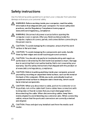
... repairs as the metal at www.dell.com/regulatory_compliance. After you must disengage before opening the computer cover or panels. WARNING: Before working inside your computer, read the safety information that the work , periodically touch an unpainted metal surface to dissipate static electricity, which could harm internal components. Safety instructions Use the following safety guidelines to protect your computer from the media-card reader...
... repairs as the metal at www.dell.com/regulatory_compliance. After you must disengage before opening the computer cover or panels. WARNING: Before working inside your computer, read the safety information that the work , periodically touch an unpainted metal surface to dissipate static electricity, which could harm internal components. Safety instructions Use the following safety guidelines to protect your computer from the media-card reader...

Service Manual
Page 12
After working inside your computer CAUTION: Leaving stray or loose screws inside your computer may severely damage your computer. 1 Replace all screws and ensure that no stray screws remain inside your computer. 2 Connect any external devices, peripherals, and cables you removed before working on your computer. 3 Replace any media cards, discs, and any other parts that you removed before working on your computer. 4 Connect your computer and all attached devices to their electrical outlets. 5 Turn on your computer. 12
After working inside your computer CAUTION: Leaving stray or loose screws inside your computer may severely damage your computer. 1 Replace all screws and ensure that no stray screws remain inside your computer. 2 Connect any external devices, peripherals, and cables you removed before working on your computer. 3 Replace any media cards, discs, and any other parts that you removed before working on your computer. 4 Connect your computer and all attached devices to their electrical outlets. 5 Turn on your computer. 12

Service Manual
Page 28
... battery resets the BIOS setup program's settings to default. Removing the coin-cell battery WARNING: Before working inside your computer, read the safety information that you note the BIOS setup program's settings before removing the coin-cell battery. It is recommended that shipped with your computer and follow the instructions in Before working inside your computer. Procedure 1 Disconnect the coin-cell battery cable from the system board. 2 Note the cable routing and remove...
... battery resets the BIOS setup program's settings to default. Removing the coin-cell battery WARNING: Before working inside your computer, read the safety information that you note the BIOS setup program's settings before removing the coin-cell battery. It is recommended that shipped with your computer and follow the instructions in Before working inside your computer. Procedure 1 Disconnect the coin-cell battery cable from the system board. 2 Note the cable routing and remove...

Service Manual
Page 30
... www.dell.com/regulatory_compliance. Replacing the coin-cell battery WARNING: Before working inside your computer, read the safety information that shipped with your computer and follow the instructions in Before working inside your computer. Procedure 1 Adhere the coin-cell battery to the system board. 2 Route the cable through the routing guide on the system board. 3 Connect the coin-cell battery cable to the system board. After working inside your...
... www.dell.com/regulatory_compliance. Replacing the coin-cell battery WARNING: Before working inside your computer, read the safety information that shipped with your computer and follow the instructions in Before working inside your computer. Procedure 1 Adhere the coin-cell battery to the system board. 2 Route the cable through the routing guide on the system board. 3 Connect the coin-cell battery cable to the system board. After working inside your...

Service Manual
Page 41
... with the pins on the system board and place the hard drive in the computer base. 6 Replace the screws that secure the hard-drive bracket to the hard drive. 5 Align the connector on the hard-drive assembly. 8 Connect the speaker cable to the computer base. 7 Route the speaker cable through the routing guides on the hard drive with your computer and follow the instructions in After working inside your computer. CAUTION: Hard drives are fragile...
... with the pins on the system board and place the hard drive in the computer base. 6 Replace the screws that secure the hard-drive bracket to the hard drive. 5 Align the connector on the hard-drive assembly. 8 Connect the speaker cable to the computer base. 7 Route the speaker cable through the routing guides on the hard drive with your computer and follow the instructions in After working inside your computer. CAUTION: Hard drives are fragile...

Service Manual
Page 44
Replacing the speakers WARNING: Before working inside your computer, read the safety information that secure the speakers to the computer base. 3 Route the speaker cable through the routing guides. 4 Connect the speaker cable to the system board. For more safety best practices, see the Regulatory Compliance home page at www.dell.com/regulatory_compliance. After working inside your computer, follow the steps in After working inside your computer. Procedure...
Replacing the speakers WARNING: Before working inside your computer, read the safety information that secure the speakers to the computer base. 3 Route the speaker cable through the routing guides. 4 Connect the speaker cable to the system board. For more safety best practices, see the Regulatory Compliance home page at www.dell.com/regulatory_compliance. After working inside your computer, follow the steps in After working inside your computer. Procedure...
Service Manual
Page 55
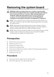
... reconnect the cables correctly after you replace the system board. NOTE: Your computer's Service Tag is stored in "Removing the hard drive". 6 Remove the mSATA card . 7 Remove the heat sink. You must make the desired changes again after you have made to step 4 in the system board. Procedure 1 Disconnect the fan cable from the system board. 2 Peel off the tape from step 1 to the BIOS using the BIOS setup program.
... reconnect the cables correctly after you replace the system board. NOTE: Your computer's Service Tag is stored in "Removing the hard drive". 6 Remove the mSATA card . 7 Remove the heat sink. You must make the desired changes again after you have made to step 4 in the system board. Procedure 1 Disconnect the fan cable from the system board. 2 Peel off the tape from step 1 to the BIOS using the BIOS setup program.
Service Manual
Page 58
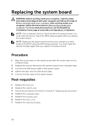
... the instructions in Before working inside your computer. Post-requisites 1 Replace the heat sink. 2 Replace the mSATA card. 3 Follow the procedure from step 5 to step 8 in the BIOS setup program after you have made to the system board. NOTE: Replacing the system board removes any changes you replace the system board. You must enter the Service Tag in "Replacing the hard drive". 4 Replace the computer base. 5 Replace the wireless card. 6 Replace the base cover. 7 Replace the memory module...
... the instructions in Before working inside your computer. Post-requisites 1 Replace the heat sink. 2 Replace the mSATA card. 3 Follow the procedure from step 5 to step 8 in the BIOS setup program after you have made to the system board. NOTE: Replacing the system board removes any changes you replace the system board. You must enter the Service Tag in "Replacing the hard drive". 4 Replace the computer base. 5 Replace the wireless card. 6 Replace the base cover. 7 Replace the memory module...
Quick Start Guide - Windows 8
Page 1
...Recovery Dell Help & Support Dell Dell Dell Dell Product support and manuals Contact Dell 与 Dell Dell Dell Regulatory and safety Regulatory model Regulatory type Computer model © 2015 Dell Inc. © 2015 Microsoft Corporation. Inspiron 24 7000 Series Quick Start Guide 1 Set up the keyboard and mouse See the documentation that shipped with the keyboard and mouse 2 Connect the power adapter and press the power button 3 Finish Windows setup 完成 Windows Windows 設定 Windows Windows Enable security and updates Connect...
...Recovery Dell Help & Support Dell Dell Dell Dell Product support and manuals Contact Dell 与 Dell Dell Dell Regulatory and safety Regulatory model Regulatory type Computer model © 2015 Dell Inc. © 2015 Microsoft Corporation. Inspiron 24 7000 Series Quick Start Guide 1 Set up the keyboard and mouse See the documentation that shipped with the keyboard and mouse 2 Connect the power adapter and press the power button 3 Finish Windows setup 完成 Windows Windows 設定 Windows Windows Enable security and updates Connect...


