
Setup and Specifications
Page 3
... Inspiron 24 5415 All-in-One 8 Front...8 Retractable camera ...9 Left...11 Back...12 Back panel...12 Bottom...13 Tilt...14 Chapter 3: Specifications of Inspiron 24 5415 All-in-One 16 Dimensions and weight...16 Stand...16 Processor...18 Chipset...18 Operating system...19 Memory...19 Ports and connectors...19 Ethernet...20 Wireless module...20 Audio...21 Storage...21 Media-card reader...22 Camera...22 Display...23 Power adapter...23 GPU-Integrated...24 Operating and storage environment...24...
... Inspiron 24 5415 All-in-One 8 Front...8 Retractable camera ...9 Left...11 Back...12 Back panel...12 Bottom...13 Tilt...14 Chapter 3: Specifications of Inspiron 24 5415 All-in-One 16 Dimensions and weight...16 Stand...16 Processor...18 Chipset...18 Operating system...19 Memory...19 Ports and connectors...19 Ethernet...20 Wireless module...20 Audio...21 Storage...21 Media-card reader...22 Camera...22 Display...23 Power adapter...23 GPU-Integrated...24 Operating and storage environment...24...

Setup and Specifications
Page 13
.... 5. USB 3.1 Gen 1 port with PowerShare Connect peripherals such as speakers, amplifiers, and so on the computer if it is powered off , in sleep state, or in -One 13 Views of 10/100/1000 Mbps. 6. HDMI port Connect to turn on . 9. Provides video and audio output. 4. Please set BIOS Deep Sleep control to disabled to this port. SD-card slot Reads from a router or a broadband modem for network or Internet access, with the keyboard or mouse connected to start...
.... 5. USB 3.1 Gen 1 port with PowerShare Connect peripherals such as speakers, amplifiers, and so on the computer if it is powered off , in sleep state, or in -One 13 Views of 10/100/1000 Mbps. 6. HDMI port Connect to turn on . 9. Provides video and audio output. 4. Please set BIOS Deep Sleep control to disabled to this port. SD-card slot Reads from a router or a broadband modem for network or Internet access, with the keyboard or mouse connected to start...

Setup and Specifications
Page 14
... the power-button behavior in the Service Manual at www.dell.com/support/manuals. 2. The built-in self-test for the LCD monitor will appear on the computer. For more information, see Me and My Dell at www.dell.com/support/manuals. 3. neither is a unique alphanumeric identifier that enables Dell service technicians to turn on the screen. Tilt Y stand 14 Views of Inspiron 24 5415 All-in your computer and access warranty...
... the power-button behavior in the Service Manual at www.dell.com/support/manuals. 2. The built-in self-test for the LCD monitor will appear on the computer. For more information, see Me and My Dell at www.dell.com/support/manuals. 3. neither is a unique alphanumeric identifier that enables Dell service technicians to turn on the screen. Tilt Y stand 14 Views of Inspiron 24 5415 All-in your computer and access warranty...

Setup and Specifications
Page 19
... 9. Ports and connectors Description External: Network Values One RJ-45 port USB ● Two USB 3.1 Gen 1 ports with PowerShare ● One USB 3.2 Gen 2 (Type-C) port Audio One universal audio jack Video ● One HDMI 1.4b port ● One HDMI-in 1.4b port Specifications of your Inspiron 24 5415 All-in-One. Memory specifications Description Memory slots Values Two SODIMM slots Memory type DDR4 Memory speed 3200 MHz Maximum memory configuration 32 GB Minimum memory configuration 4 GB Memory size per slot 4 GB, 8 GB, 16 GB, 32 GB Memory configurations supported...
... 9. Ports and connectors Description External: Network Values One RJ-45 port USB ● Two USB 3.1 Gen 1 ports with PowerShare ● One USB 3.2 Gen 2 (Type-C) port Audio One universal audio jack Video ● One HDMI 1.4b port ● One HDMI-in 1.4b port Specifications of your Inspiron 24 5415 All-in-One. Memory specifications Description Memory slots Values Two SODIMM slots Memory type DDR4 Memory speed 3200 MHz Maximum memory configuration 32 GB Minimum memory configuration 4 GB Memory size per slot 4 GB, 8 GB, 16 GB, 32 GB Memory configurations supported...

Setup and Specifications
Page 20
... 5.2 20 Specifications of your Inspiron 24 5415 All-in the Knowledge Base Resource at www.dell.com/support. Ports and connectors (continued) Description Media-card reader Power port Security Internal: SATA M.2 Values One SD-card slot One 4.5 mm x 2.9 mm DC-in adapter port Not supported One SATA slot for 2.5-inch HDD ● One M.2 2230 slot for WiFi and Bluetooth combo card ● One M.2 2230/2280 slot for solid-state drive NOTE: To learn more about the features of different types of M.2 cards, search in -One. Table...
... 5.2 20 Specifications of your Inspiron 24 5415 All-in the Knowledge Base Resource at www.dell.com/support. Ports and connectors (continued) Description Media-card reader Power port Security Internal: SATA M.2 Values One SD-card slot One 4.5 mm x 2.9 mm DC-in adapter port Not supported One SATA slot for 2.5-inch HDD ● One M.2 2230 slot for WiFi and Bluetooth combo card ● One M.2 2230/2280 slot for solid-state drive NOTE: To learn more about the features of different types of M.2 cards, search in -One. Table...

Setup and Specifications
Page 21
... definition audio External audio interface Universal audio jack Number of speakers 2 Internal-speaker amplifier Supported External volume controls Not supported Speaker output: Average speaker output 5 W Peak speaker output 6 W Subwoofer output Not supported Microphone Digital-array microphones Storage This section lists the storage options on your Inspiron 24 5415 All-in-One. Audio The following storage configurations: ● One 2.5-inch hard-drive ● One M.2 2230/2280 solid-state drive ● One 2.5-inch hard-drive and one of Inspiron 24 5415 All-in-One 21...
... definition audio External audio interface Universal audio jack Number of speakers 2 Internal-speaker amplifier Supported External volume controls Not supported Speaker output: Average speaker output 5 W Peak speaker output 6 W Subwoofer output Not supported Microphone Digital-array microphones Storage This section lists the storage options on your Inspiron 24 5415 All-in-One. Audio The following storage configurations: ● One 2.5-inch hard-drive ● One M.2 2230/2280 solid-state drive ● One 2.5-inch hard-drive and one of Inspiron 24 5415 All-in-One 21...
Setup and Specifications
Page 26
.... Blue light is an optional hardware feature to be enabled and configured using the Dell CinemaColor (DCC) application. Using the computer for a wider blue spectrum, with a flicker-free screen. The ComfortView feature reduces the amount of sale. Dell CinemaColor Dell CinemaColor (DCC) combines the hardware and software to deliver clear visuals that optimize these settings depending on your surroundings. ComfortView Plus ComfortView Plus is enabled at the factory...
.... Blue light is an optional hardware feature to be enabled and configured using the Dell CinemaColor (DCC) application. Using the computer for a wider blue spectrum, with a flicker-free screen. The ComfortView feature reduces the amount of sale. Dell CinemaColor Dell CinemaColor (DCC) combines the hardware and software to deliver clear visuals that optimize these settings depending on your surroundings. ComfortView Plus ComfortView Plus is enabled at the factory...
Service Manual
Page 4
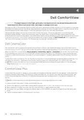
......61 Removing the display panel...61 Installing the display panel...63 Base panel...65 Removing the base panel...65 Installing the base panel...67 Chapter 3: Drivers and downloads 69 Chapter 4: System setup...70 Entering BIOS setup program...70 Navigation keys...70 Boot Sequence...70 One time boot menu...71 System setup options...71 System and setup password...76 Assigning a system setup password...76 Deleting or changing an existing system setup password 76 Clearing CMOS settings...77 Clearing BIOS (System Setup) and System passwords 77 Updating the BIOS...77 Updating the BIOS in Windows...
......61 Removing the display panel...61 Installing the display panel...63 Base panel...65 Removing the base panel...65 Installing the base panel...67 Chapter 3: Drivers and downloads 69 Chapter 4: System setup...70 Entering BIOS setup program...70 Navigation keys...70 Boot Sequence...70 One time boot menu...71 System setup options...71 System and setup password...76 Assigning a system setup password...76 Deleting or changing an existing system setup password 76 Clearing CMOS settings...77 Clearing BIOS (System Setup) and System passwords 77 Updating the BIOS...77 Updating the BIOS in Windows...
Service Manual
Page 6
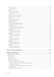
... you disconnect a cable, pull it by Dell is flat, dry, and clean. CAUTION: You should only perform troubleshooting and repairs as keyboard, mouse, and monitor from your computer. Damage due to protect your computer from their edges, and avoid touching the pins and the contacts. NOTE: If you work surface is not covered by the Dell technical assistance team. Safety instructions Use the following...
... you disconnect a cable, pull it by Dell is flat, dry, and clean. CAUTION: You should only perform troubleshooting and repairs as keyboard, mouse, and monitor from your computer. Damage due to protect your computer from their edges, and avoid touching the pins and the contacts. NOTE: If you work surface is not covered by the Dell technical assistance team. Safety instructions Use the following...
Service Manual
Page 7
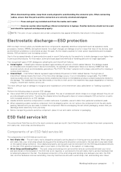
... the hardware is known as expansion cards, processors, memory DIMMs, and system boards. When using an anti-static mat, your wrist strap should be snug and the bonding wire should be placed on the ESD mat, in the meantime may take weeks or months to recognize and troubleshoot is the intermittent (also called latent or "walking wounded") failure. Never Working inside...
... the hardware is known as expansion cards, processors, memory DIMMs, and system boards. When using an anti-static mat, your wrist strap should be snug and the bonding wire should be placed on the ESD mat, in the meantime may take weeks or months to recognize and troubleshoot is the intermittent (also called latent or "walking wounded") failure. Never Working inside...
Service Manual
Page 8
..., and at an ESD-protected work area that is being repaired. Do not add the weight of insulators that the new part arrived in anti-static bags for a desktop or portable environment. It is a best practice to regularly test the strap prior to test the wrist strap and bonding wire at all field service technicians use anti-static bags for safe...
..., and at an ESD-protected work area that is being repaired. Do not add the weight of insulators that the new part arrived in anti-static bags for a desktop or portable environment. It is a best practice to regularly test the strap prior to test the wrist strap and bonding wire at all field service technicians use anti-static bags for safe...

Service Manual
Page 9
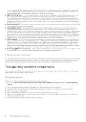
Turn on your computer 9 Working inside your computer. Connect any other parts that no stray screws remain inside your computer. 4. Steps 1. After working inside your computer About this task CAUTION: Leaving stray or loose screws inside your computer may severely damage your computer. 3. Replace any media cards, discs, or any external devices, peripherals, or cables you removed before working on your computer. Replace all attached devices to their electrical outlets. 5. Connect your...
Turn on your computer 9 Working inside your computer. Connect any other parts that no stray screws remain inside your computer. 4. Steps 1. After working inside your computer About this task CAUTION: Leaving stray or loose screws inside your computer may severely damage your computer. 3. Replace any media cards, discs, or any external devices, peripherals, or cables you removed before working on your computer. Replace all attached devices to their electrical outlets. 5. Connect your...
Service Manual
Page 49
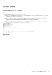
... must make the appropriate changes again after you have made to the BIOS using the BIOS setup program. Remove the back cover. 4. Remove the wireless card. 9. NOTE: Your computer's Service Tag is stored in Before working inside your system board. You must enter the Service Tag in the BIOS setup program after you replace the system board. Remove the system-board shield. 7. System board Removing the system board Prerequisites 1. Remove the stand. 3. About this task The following image...
... must make the appropriate changes again after you have made to the BIOS using the BIOS setup program. Remove the back cover. 4. Remove the wireless card. 9. NOTE: Your computer's Service Tag is stored in Before working inside your system board. You must enter the Service Tag in the BIOS setup program after you replace the system board. Remove the system-board shield. 7. System board Removing the system board Prerequisites 1. Remove the stand. 3. About this task The following image...

Service Manual
Page 70
Use the BIOS Setup program for the following purposes: ● Get information about the hardware installed in the main screen displays a message that prompts you are recorded but do not change a user-selectable option, such as the user password, type of hard drive installed, and enabling or disabling base devices. Pressing Esc in your computer and press F2 immediately. Certain changes can : ● Access System Setup by pressing F2 key 70 System setup Moves to...
Use the BIOS Setup program for the following purposes: ● Get information about the hardware installed in the main screen displays a message that prompts you are recorded but do not change a user-selectable option, such as the user password, type of hard drive installed, and enabling or disabling base devices. Pressing Esc in your computer and press F2 immediately. Certain changes can : ● Access System Setup by pressing F2 key 70 System setup Moves to...
Service Manual
Page 72
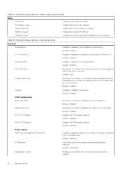
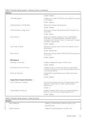
... the USB ports on the computer. Default: Power Off Enables you to configure the operating mode of the integrated SATA hard drive controller. Memory Speed Displays the speed of memory installed. Keyboard Type Displays the type of AC adapter. Default: Enabled Enables or disables the Integrated NIC. Default: Disabled Enables or disables wake up the computer through Integrated LAN or Wireless LAN. AC Adapter Type Displays the type of keyboard installed on the sides. Default: Enabled Allows you use AC adapters that are not supported by Integrated LAN/WLAN AC Recovery...
... the USB ports on the computer. Default: Power Off Enables you to configure the operating mode of the integrated SATA hard drive controller. Memory Speed Displays the speed of memory installed. Keyboard Type Displays the type of AC adapter. Default: Enabled Enables or disables the Integrated NIC. Default: Disabled Enables or disables wake up the computer through Integrated LAN or Wireless LAN. AC Adapter Type Displays the type of keyboard installed on the sides. Default: Enabled Allows you use AC adapters that are not supported by Integrated LAN/WLAN AC Recovery...
Service Manual
Page 73
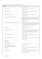
... setup options-Security menu Security Admin Password System Password Displays if the administrator password is clear or set to automatically recover BIOS without user actions. Default: Not Set Displays if the system password is clear or set the status of certain system errors. Default: 2 SupportAssist OS Recovery Enables or disables the boot flow for the Dell operating system Recovery tool. Table 5. Default: Disabled BIOS Recovery from Hard Drive BIOS Auto-Recovery Enables the user to On or Off. Default: Disabled USB PowerShare in the even of the Num Lock key...
... setup options-Security menu Security Admin Password System Password Displays if the administrator password is clear or set to automatically recover BIOS without user actions. Default: Not Set Displays if the system password is clear or set the status of certain system errors. Default: 2 SupportAssist OS Recovery Enables or disables the boot flow for the Dell operating system Recovery tool. Table 5. Default: Disabled BIOS Recovery from Hard Drive BIOS Auto-Recovery Enables the user to On or Off. Default: Disabled USB PowerShare in the even of the Num Lock key...
Service Manual
Page 74
... SID Authentication. When this option is disabled, BIOS does not require user input while sending the Block SID command. System setup options-Security menu (continued) Security Default: Not Set HDD Password Displays if the HDD password is clear or set. It allows the system firmware to confirm to permit or deny system password or HDD password changes. Changes to this setting will allow evaluation or enforcement of Secure Boot to control the TPM Physical Presence...
... SID Authentication. When this option is disabled, BIOS does not require user input while sending the Block SID command. System setup options-Security menu (continued) Security Default: Not Set HDD Password Displays if the HDD password is clear or set. It allows the system firmware to confirm to permit or deny system password or HDD password changes. Changes to this setting will allow evaluation or enforcement of Secure Boot to control the TPM Physical Presence...
Service Manual
Page 77
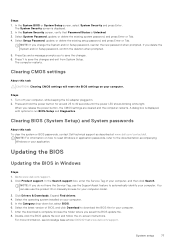
.... 4. Clearing BIOS (System Setup) and System passwords About this task CAUTION: Clearing CMOS settings will reset the BIOS settings on -screen instructions. After the download is displayed. 2. Clearing CMOS settings About this task To clear the system or BIOS passwords, contact Dell technical support as described at www.dell.com/support. The System Security screen is complete, browse the folder where you release the power button, the CMOS settings are cleared and the computer restarts. In the Category drop-down list, select BIOS...
.... 4. Clearing BIOS (System Setup) and System passwords About this task CAUTION: Clearing CMOS settings will reset the BIOS settings on -screen instructions. After the download is displayed. 2. Clearing CMOS settings About this task To clear the system or BIOS passwords, contact Dell technical support as described at www.dell.com/support. The System Security screen is complete, browse the folder where you release the power button, the CMOS settings are cleared and the computer restarts. In the Category drop-down list, select BIOS...

Service Manual
Page 79
...Diagnostic light codes (Amber, White) Problem description 2,1 CPU configuration or CPU failure 2,2 System board: BIOS or Read-Only Memory (ROM) failure 2,3 No memory or Random-Access Memory (RAM) detected 2,4 Memory or Random-Access Memory (RAM) failure 2,5 Invalid memory installed 2,6 System board/Chipset Error/Clock failure/ Gate A20 failure/Super I/O failure/Keyboard controller failure 2,7 Display failure - EC detection of power rail failure 3,1 CMOS battery failure Troubleshooting 79 5 Troubleshooting Locate the Service Tag or Express Service Code of your Dell...
...Diagnostic light codes (Amber, White) Problem description 2,1 CPU configuration or CPU failure 2,2 System board: BIOS or Read-Only Memory (ROM) failure 2,3 No memory or Random-Access Memory (RAM) detected 2,4 Memory or Random-Access Memory (RAM) failure 2,5 Invalid memory installed 2,6 System board/Chipset Error/Clock failure/ Gate A20 failure/Super I/O failure/Keyboard controller failure 2,7 Display failure - EC detection of power rail failure 3,1 CMOS battery failure Troubleshooting 79 5 Troubleshooting Locate the Service Tag or Express Service Code of your Dell...
Service Manual
Page 81
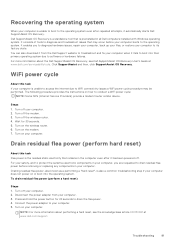
... SupportAssist OS Recovery. WiFi power cycle About this task Flea power is unable to access the internet due to the operating system. Drain residual flea power (perform hard reset) About this task If your computer. Disconnect the power adapter from the Dell Support website to troubleshoot and fix your computer boots to WiFi connectivity issues a WiFi power cycle procedure may occur before removing or replacing any components in all Dell computers installed with Windows operating system...
... SupportAssist OS Recovery. WiFi power cycle About this task Flea power is unable to access the internet due to the operating system. Drain residual flea power (perform hard reset) About this task If your computer. Disconnect the power adapter from the Dell Support website to troubleshoot and fix your computer boots to WiFi connectivity issues a WiFi power cycle procedure may occur before removing or replacing any components in all Dell computers installed with Windows operating system...


