Specifications
Page 1
... Specifications Copyright © 2015 Dell Inc. This product is protected by U.S. Dell™ and the Dell logo are trademarks of their respective companies. 2015 ‑ 05 Rev. A00 Regulatory model: W12C | Type: W12C002 Computer model: Inspiron 24-3452 NOTE: The images in the United States and/or other marks and names mentioned herein may differ from your computer depending on the configuration...
... Specifications Copyright © 2015 Dell Inc. This product is protected by U.S. Dell™ and the Dell logo are trademarks of their respective companies. 2015 ‑ 05 Rev. A00 Regulatory model: W12C | Type: W12C002 Computer model: Inspiron 24-3452 NOTE: The images in the United States and/or other marks and names mentioned herein may differ from your computer depending on the configuration...

Specifications
Page 5
The two lights next to the connector indicate the connectivity status and network activity. 4 Power-adapter port Connect a power adapter to provide power to 480 Mbps. 3 Network port Connect an Ethernet (RJ45) cable from a router or a broadband modem for network or internet access. Specifications Front Back Left Right Views 1 43 2 Back Tilt 1 Audio-out port Connect audio-output devices such as speakers, amplifiers, and so on. 2 USB 2.0 ports (2) Connect peripherals such as storage devices, printers, and so on. Provide data transfer speeds up to your computer.
The two lights next to the connector indicate the connectivity status and network activity. 4 Power-adapter port Connect a power adapter to provide power to 480 Mbps. 3 Network port Connect an Ethernet (RJ45) cable from a router or a broadband modem for network or internet access. Specifications Front Back Left Right Views 1 43 2 Back Tilt 1 Audio-out port Connect audio-output devices such as speakers, amplifiers, and so on. 2 USB 2.0 ports (2) Connect peripherals such as storage devices, printers, and so on. Provide data transfer speeds up to your computer.

Specifications
Page 9
Views Memory Slot Type Speed Configurations supported Specifications One SODIMM slot Single-channel DDR3L Up to 1600 MHz 2 GB, 4 GB, and 8 GB Dimensions and weight System information Memory Ports and connectors Communications Video Audio Media-card reader Display Camera Stand Power adapter Computer environment Storage
Views Memory Slot Type Speed Configurations supported Specifications One SODIMM slot Single-channel DDR3L Up to 1600 MHz 2 GB, 4 GB, and 8 GB Dimensions and weight System information Memory Ports and connectors Communications Video Audio Media-card reader Display Camera Stand Power adapter Computer environment Storage

Specifications
Page 10
Views Ports and connectors External: Network USB Audio/Video Internal: M.2 card Specifications One RJ45 port • Two USB 2.0 ports • Two USB 3.0 ports • One combo jack port • One audio line-out port One M.2 card slot for WLAN and Bluetooth Dimensions and weight System information Memory Ports and connectors Communications Video Audio Media-card reader Display Camera Stand Power adapter Computer environment Storage
Views Ports and connectors External: Network USB Audio/Video Internal: M.2 card Specifications One RJ45 port • Two USB 2.0 ports • Two USB 3.0 ports • One combo jack port • One audio line-out port One M.2 card slot for WLAN and Bluetooth Dimensions and weight System information Memory Ports and connectors Communications Video Audio Media-card reader Display Camera Stand Power adapter Computer environment Storage

Specifications
Page 11
Views Communications Ethernet Wireless Specifications 10/100/1000 Mbps Ethernet controller integrated on system board • Wi-Fi 802.11b/g/n • Wi-Fi 802.11ac • Bluetooth 4.0 Dimensions and weight System information Memory Ports and connectors Communications Video Audio Media-card reader Display Camera Stand Power adapter Computer environment Storage
Views Communications Ethernet Wireless Specifications 10/100/1000 Mbps Ethernet controller integrated on system board • Wi-Fi 802.11b/g/n • Wi-Fi 802.11ac • Bluetooth 4.0 Dimensions and weight System information Memory Ports and connectors Communications Video Audio Media-card reader Display Camera Stand Power adapter Computer environment Storage

Specifications
Page 14
Views Storage Interface Hard drive Optical drive Specifications • SATA 3 Gbps for optical drive • SATA 6 Gbps for hard drive One 2.5-in drive One 9.5-mm DVD+/-RW drive (optional) Dimensions and weight System information Memory Ports and connectors Communications Video Audio Media-card reader Display Camera Stand Power adapter Computer environment Storage
Views Storage Interface Hard drive Optical drive Specifications • SATA 3 Gbps for optical drive • SATA 6 Gbps for hard drive One 2.5-in drive One 9.5-mm DVD+/-RW drive (optional) Dimensions and weight System information Memory Ports and connectors Communications Video Audio Media-card reader Display Camera Stand Power adapter Computer environment Storage

Specifications
Page 20
....04-1985 Operating Temperature range 0°C to 35°C (32°F to 95°F) Relative humidity (maximum) 10% to 90% (non-condensing) Vibration (maximum)* 0.66 GRMS Shock (maximum) 110 G† Altitude (maximum) -15.2 m to 3048 m (-50 ft to 35,000 ft) Dimensions and weight System information Memory Ports and connectors Communications Video Audio Media-card reader Display Camera Stand Power adapter Computer...
....04-1985 Operating Temperature range 0°C to 35°C (32°F to 95°F) Relative humidity (maximum) 10% to 90% (non-condensing) Vibration (maximum)* 0.66 GRMS Shock (maximum) 110 G† Altitude (maximum) -15.2 m to 3048 m (-50 ft to 35,000 ft) Dimensions and weight System information Memory Ports and connectors Communications Video Audio Media-card reader Display Camera Stand Power adapter Computer...
Service Manual
Page 1
Inspiron 24 3000 Series Service Manual Computer Model: Inspiron 24-3452 Regulatory Model: W12C Regulatory Type: W12C002
Inspiron 24 3000 Series Service Manual Computer Model: Inspiron 24-3452 Regulatory Model: W12C Regulatory Type: W12C002

Service Manual
Page 4
Removing the hard drive 23 Prerequisites...23 Procedure...23 Replacing the hard drive 26 Procedure...26 Post-requisites 26 Removing the memory module 27 Prerequisites...27 Procedure...27 Replacing the memory module 29 Procedure...29 Post-requisites 30 Removing the wireless card 31 Prerequisites...31 Procedure...31 Replacing the wireless card 33 Procedure...33 Post-requisites 34 Removing the heat sink 35 Prerequisites...35 Procedure...35 Replacing the heat sink 37 Procedure...37 Post-requisites 37 4
Removing the hard drive 23 Prerequisites...23 Procedure...23 Replacing the hard drive 26 Procedure...26 Post-requisites 26 Removing the memory module 27 Prerequisites...27 Procedure...27 Replacing the memory module 29 Procedure...29 Post-requisites 30 Removing the wireless card 31 Prerequisites...31 Procedure...31 Replacing the wireless card 33 Procedure...33 Post-requisites 34 Removing the heat sink 35 Prerequisites...35 Procedure...35 Replacing the heat sink 37 Procedure...37 Post-requisites 37 4

Service Manual
Page 8
Before working inside your computer depending on the configuration you ordered. CAUTION: Place the computer on , from your computer. 6 Remove any media card and optical disc from your computer. - NOTE: The images in this document may differ from your computer. 5 Disconnect all cables such as telephone cables, network cables and so on, from your computer CAUTION: To avoid damaging the components and cards, handle them...
Before working inside your computer depending on the configuration you ordered. CAUTION: Place the computer on , from your computer. 6 Remove any media card and optical disc from your computer. - NOTE: The images in this document may differ from your computer. 5 Disconnect all cables such as telephone cables, network cables and so on, from your computer CAUTION: To avoid damaging the components and cards, handle them...

Service Manual
Page 9
... cards, handle them evenly aligned to the power source. See the safety instructions that you finish working inside your computer, read the safety information that is not authorized by Dell is flat and clean. WARNING: Disconnect all covers, panels, and screws before opening the computer cover or panels. After you must disengage before disconnecting the cable. CAUTION: You should only perform troubleshooting and repairs...
... cards, handle them evenly aligned to the power source. See the safety instructions that you finish working inside your computer, read the safety information that is not authorized by Dell is flat and clean. WARNING: Disconnect all covers, panels, and screws before opening the computer cover or panels. After you must disengage before disconnecting the cable. CAUTION: You should only perform troubleshooting and repairs...

Service Manual
Page 11
After working inside your computer CAUTION: Leaving stray or loose screws inside your computer may severely damage your computer. 1 Replace all screws and ensure that no stray screws remain inside your computer. 2 Connect any external devices, peripherals, and cables you removed before working on your computer. 3 Replace any media cards, discs, and any other parts that you removed before working on your computer. 4 Connect your computer and all attached devices to their electrical outlets. 5 Turn on your computer. 11
After working inside your computer CAUTION: Leaving stray or loose screws inside your computer may severely damage your computer. 1 Replace all screws and ensure that no stray screws remain inside your computer. 2 Connect any external devices, peripherals, and cables you removed before working on your computer. 3 Replace any media cards, discs, and any other parts that you removed before working on your computer. 4 Connect your computer and all attached devices to their electrical outlets. 5 Turn on your computer. 11
Service Manual
Page 12
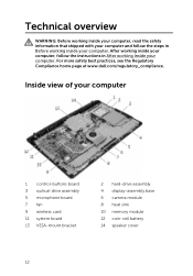
..., read the safety information that shipped with your computer and follow the instructions in Before working inside your computer 1 control-buttons board 3 optical-drive assembly 5 microphone board 7 fan 9 wireless card 11 system board 13 VESA-mount bracket 2 hard-drive assembly 4 display-assembly base 6 camera module 8 heat sink 10 memory module 12 coin-cell battery 14 speaker cover 12 Inside view of your computer. For more safety best practices, see the Regulatory...
..., read the safety information that shipped with your computer and follow the instructions in Before working inside your computer 1 control-buttons board 3 optical-drive assembly 5 microphone board 7 fan 9 wireless card 11 system board 13 VESA-mount bracket 2 hard-drive assembly 4 display-assembly base 6 camera module 8 heat sink 10 memory module 12 coin-cell battery 14 speaker cover 12 Inside view of your computer. For more safety best practices, see the Regulatory...
Service Manual
Page 23
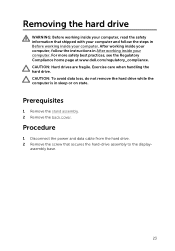
... more safety best practices, see the Regulatory Compliance home page at www.dell.com/regulatory_compliance. CAUTION: Hard drives are fragile. Procedure 1 Disconnect the power and data cable from the hard drive. 2 Remove the screw that shipped with your computer and follow the instructions in sleep or on state. Removing the hard drive WARNING: Before working inside your computer, read the safety information that secures the...
... more safety best practices, see the Regulatory Compliance home page at www.dell.com/regulatory_compliance. CAUTION: Hard drives are fragile. Procedure 1 Disconnect the power and data cable from the hard drive. 2 Remove the screw that shipped with your computer and follow the instructions in sleep or on state. Removing the hard drive WARNING: Before working inside your computer, read the safety information that secures the...
Service Manual
Page 24
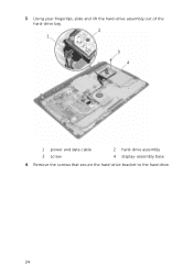
3 Using your fingertips, slide and lift the hard-drive assembly out of the hard-drive bay. 1 power and data cable 3 screw 2 hard-drive assembly 4 display-assembly base 4 Remove the screws that secure the hard-drive bracket to the hard drive. 24
3 Using your fingertips, slide and lift the hard-drive assembly out of the hard-drive bay. 1 power and data cable 3 screw 2 hard-drive assembly 4 display-assembly base 4 Remove the screws that secure the hard-drive bracket to the hard drive. 24
Service Manual
Page 26
... screw hole on the displayassembly base. 4 Replace the screw that secure the hard-drive bracket to the hard drive. 3 Slide the hard-drive assembly into the hard-drive bay and align the screw hole on the hard drive. 2 Replace the screws that secures the hard-drive assembly to the displayassembly base. 5 Connect the power and data cable to the hard drive. After working inside your computer, follow the steps in After...
... screw hole on the displayassembly base. 4 Replace the screw that secure the hard-drive bracket to the hard drive. 3 Slide the hard-drive assembly into the hard-drive bay and align the screw hole on the hard drive. 2 Replace the screws that secures the hard-drive assembly to the displayassembly base. 5 Connect the power and data cable to the hard drive. After working inside your computer, follow the steps in After...
Service Manual
Page 50
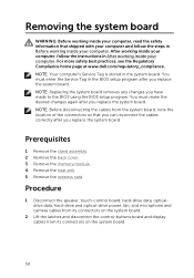
... data, hard-drive and optical-drive power, fan, and microphone and camera cables from its connectors on the system board. 2 Lift the latches and disconnect the control-buttons board and display cables from the system board, note the location of the connectors so that shipped with your computer and follow the instructions in the system board. Prerequisites 1 Remove the stand assembly. 2 Remove the back cover. 3 Remove the memory module. 4 Remove the heat sink. 5 Remove the wireless card. For...
... data, hard-drive and optical-drive power, fan, and microphone and camera cables from its connectors on the system board. 2 Lift the latches and disconnect the control-buttons board and display cables from the system board, note the location of the connectors so that shipped with your computer and follow the instructions in the system board. Prerequisites 1 Remove the stand assembly. 2 Remove the back cover. 3 Remove the memory module. 4 Remove the heat sink. 5 Remove the wireless card. For...
Service Manual
Page 53
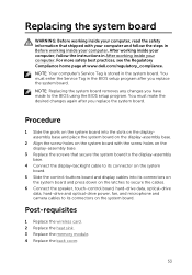
... the ports on the system board into its connectors on the system board and press down on the latches to secure the cables. 6 Connect the speaker, touch-control board, hard-drive data, optical-drive data, hard-drive and optical-drive power, fan, and microphone and camera cables to its connectors on the display-assembly base. 3 Replace the screws that shipped with your computer and follow the instructions in the system board. Replacing the system board WARNING: Before working inside...
... the ports on the system board into its connectors on the system board and press down on the latches to secure the cables. 6 Connect the speaker, touch-control board, hard-drive data, optical-drive data, hard-drive and optical-drive power, fan, and microphone and camera cables to its connectors on the display-assembly base. 3 Replace the screws that shipped with your computer and follow the instructions in the system board. Replacing the system board WARNING: Before working inside...

Service Manual
Page 63
... page at www.dell.com/regulatory_compliance. After working inside your computer, follow the steps in After working inside your computer. Procedure 1 Using the alignment posts and rubber grommets on the display bezel, place the speakers on the display bezel. 2 Route the speaker cable through the routing guide on the display-panel base. 7 Route and replace the speaker cable under the VESA-mount bracket. 8 Connect the speaker cable to the system board.
... page at www.dell.com/regulatory_compliance. After working inside your computer, follow the steps in After working inside your computer. Procedure 1 Using the alignment posts and rubber grommets on the display bezel, place the speakers on the display bezel. 2 Route the speaker cable through the routing guide on the display-panel base. 7 Route and replace the speaker cable under the VESA-mount bracket. 8 Connect the speaker cable to the system board.
Service Manual
Page 72
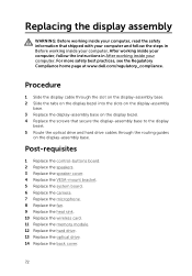
... control-buttons board. 2 Replace the speakers. 3 Replace the speaker cover. 4 Replace the VESA-mount bracket. 5 Replace the system board. 6 Replace the camera. 7 Replace the microphone. 8 Replace the fan. 9 Replace the heat sink. 10 Replace the wireless card. 11 Replace the memory module. 12 Replace the hard drive. 13 Replace the optical drive. 14 Replace the back cover. 72 For more safety best practices, see the Regulatory Compliance home page at www.dell.com/regulatory_compliance. Procedure 1 Slide the display cable through the routing guides...
... control-buttons board. 2 Replace the speakers. 3 Replace the speaker cover. 4 Replace the VESA-mount bracket. 5 Replace the system board. 6 Replace the camera. 7 Replace the microphone. 8 Replace the fan. 9 Replace the heat sink. 10 Replace the wireless card. 11 Replace the memory module. 12 Replace the hard drive. 13 Replace the optical drive. 14 Replace the back cover. 72 For more safety best practices, see the Regulatory Compliance home page at www.dell.com/regulatory_compliance. Procedure 1 Slide the display cable through the routing guides...


