
Specifications
Page 3
... . Specifications Front Right Right Back Views 1 2 3 4 5 6 7 1 Media-card reader 5 USB 2.0 port Reads from a router or a broadband modem for network or internet access. 4 HDMI-in port Connect a gaming console, Blu‑ray player, or other HDMI‑out enabled devices. Connect peripherals such as storage devices, printers, 2 USB 2.0 ports (2) and so on . Provides data transfer speeds up to 480 Mbps. NOTE: Your computer may not support a battery depending on the configuration you ordered. Connect a power adapter to...
... . Specifications Front Right Right Back Views 1 2 3 4 5 6 7 1 Media-card reader 5 USB 2.0 port Reads from a router or a broadband modem for network or internet access. 4 HDMI-in port Connect a gaming console, Blu‑ray player, or other HDMI‑out enabled devices. Connect peripherals such as storage devices, printers, 2 USB 2.0 ports (2) and so on . Provides data transfer speeds up to 480 Mbps. NOTE: Your computer may not support a battery depending on the configuration you ordered. Connect a power adapter to...

Specifications
Page 8
Views Memory Slot Type Speed Configurations supported Specifications One SODIMM slot DDR3L 1333 MHz 2 GB, 4 GB, and 8 GB Dimensions and Weight System Information Memory Ports and Connectors Communications Video Audio Media-Card Reader Display Camera Power Adapter Battery Computer Environment Storage
Views Memory Slot Type Speed Configurations supported Specifications One SODIMM slot DDR3L 1333 MHz 2 GB, 4 GB, and 8 GB Dimensions and Weight System Information Memory Ports and Connectors Communications Video Audio Media-Card Reader Display Camera Power Adapter Battery Computer Environment Storage

Specifications
Page 13
Views Storage Interface Hard drive Specifications SATA 3 Gbps One 2.5-inch drive Dimensions and Weight System Information Memory Ports and Connectors Communications Video Audio Media-Card Reader Display Camera Power Adapter Battery Computer Environment Storage
Views Storage Interface Hard drive Specifications SATA 3 Gbps One 2.5-inch drive Dimensions and Weight System Information Memory Ports and Connectors Communications Video Audio Media-Card Reader Display Camera Power Adapter Battery Computer Environment Storage

Service Manual
Page 5
Replacing the System Board 42 Procedure...42 Post-requisites 43 Entering the Service Tag in the BIOS 43 Removing the Coin-Cell Battery 44 Prerequisites...44 Procedure...45 Replacing the Coin-Cell Battery 46 Procedure...46 Post-requisites 46 Removing the Memory Module 47 Prerequisites...47 Procedure...48 Replacing the Memory Module 49 Procedure...50 Post-requisites 50 Removing the Heat Sink 51 Prerequisites...51 Procedure...52 Replacing the Heat Sink 53 Procedure...53 Post-requisites 53 Removing the Display Assembly 54 Prerequisites...54 Procedure...54
Replacing the System Board 42 Procedure...42 Post-requisites 43 Entering the Service Tag in the BIOS 43 Removing the Coin-Cell Battery 44 Prerequisites...44 Procedure...45 Replacing the Coin-Cell Battery 46 Procedure...46 Post-requisites 46 Removing the Memory Module 47 Prerequisites...47 Procedure...48 Replacing the Memory Module 49 Procedure...50 Post-requisites 50 Removing the Heat Sink 51 Prerequisites...51 Procedure...52 Replacing the Heat Sink 53 Procedure...53 Post-requisites 53 Removing the Display Assembly 54 Prerequisites...54 Procedure...54

Service Manual
Page 7
... as telephone cables, network cables and so on, from your computer. 5 Disconnect all open files and exit all attached devices and peripherals, such as keyboard, mouse, monitor, and so on the configuration you are using a different operating system, see the documentation of your personal safety. 7 NOTE: If you ordered. Windows 8.1: On the Start screen, click or tap the power icon → Shut down instructions. 3 Disconnect your...
... as telephone cables, network cables and so on, from your computer. 5 Disconnect all open files and exit all attached devices and peripherals, such as keyboard, mouse, monitor, and so on the configuration you are using a different operating system, see the documentation of your personal safety. 7 NOTE: If you ordered. Windows 8.1: On the Start screen, click or tap the power icon → Shut down instructions. 3 Disconnect your...

Service Manual
Page 8
... inside the computer, replace all power sources before connecting to avoid bending any installed card from the network device. When connecting cables, make sure that the ports and connectors are correctly oriented and aligned. CAUTION: To disconnect a network cable, first unplug the cable from your computer, and protecting against electrostatic discharge. WARNING: Disconnect all covers, panels, and screws before opening the computer cover or panels. After you finish working inside the computer. Some cables...
... inside the computer, replace all power sources before connecting to avoid bending any installed card from the network device. When connecting cables, make sure that the ports and connectors are correctly oriented and aligned. CAUTION: To disconnect a network cable, first unplug the cable from your computer, and protecting against electrostatic discharge. WARNING: Disconnect all covers, panels, and screws before opening the computer cover or panels. After you finish working inside the computer. Some cables...

Service Manual
Page 10
After Working Inside Your Computer CAUTION: Leaving stray or loose screws inside your computer may severely damage your computer. 1 Replace all screws and make sure that no stray screws remain inside your computer. 2 Connect any external devices, peripherals, and cables you removed before working on your computer. 3 Replace any media cards, discs, and any other part(s) that you removed before working on your computer. 4 Connect your computer and all attached devices to their electrical outlets. 5 Turn on your computer. 10
After Working Inside Your Computer CAUTION: Leaving stray or loose screws inside your computer may severely damage your computer. 1 Replace all screws and make sure that no stray screws remain inside your computer. 2 Connect any external devices, peripherals, and cables you removed before working on your computer. 3 Replace any media cards, discs, and any other part(s) that you removed before working on your computer. 4 Connect your computer and all attached devices to their electrical outlets. 5 Turn on your computer. 10

Service Manual
Page 11
... Regulatory Compliance home page at dell.com/regulatory_compliance. Inside View of Your Computer 1 back cover 3 display panel 5 power-status light board 7 wireless card 9 control-buttons board 2 hard-drive assembly 4 speakers (2) 6 system-board bracket 8 antenna modules (2) 11 Technical Overview WARNING: Before working inside your computer, read the safety information that shipped with your computer, follow the steps in After Working Inside Your Computer. After working inside your computer and follow the instructions in Before Working Inside Your Computer.
... Regulatory Compliance home page at dell.com/regulatory_compliance. Inside View of Your Computer 1 back cover 3 display panel 5 power-status light board 7 wireless card 9 control-buttons board 2 hard-drive assembly 4 speakers (2) 6 system-board bracket 8 antenna modules (2) 11 Technical Overview WARNING: Before working inside your computer, read the safety information that shipped with your computer, follow the steps in After Working Inside Your Computer. After working inside your computer and follow the instructions in Before Working Inside Your Computer.

Service Manual
Page 12
System Board Components 1 memory-module slot (DDR3L) 2 hard-drive cable connector (HDD) 3 wireless-card slot (WLAN) 4 display-backlight cable connector 5 display-cable connector (LVDS) 6 speaker-cable connector (SPK) 7 power-status light board cable connector (LED) 12
System Board Components 1 memory-module slot (DDR3L) 2 hard-drive cable connector (HDD) 3 wireless-card slot (WLAN) 4 display-backlight cable connector 5 display-cable connector (LVDS) 6 speaker-cable connector (SPK) 7 power-status light board cable connector (LED) 12
Service Manual
Page 18
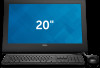
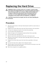
... back cover. 10 Connect the hard-drive cable to the interposer board and hard-drive assembly. 6 Turn the hard-drive assembly over. 7 Slide the hard-drive assembly into the slot on the back cover. 8 Align the screw holes on the back cover and snap the hard-drive door into place. 12 Place the computer in an upright position. 18 Exercise care when handling the hard drive. Replacing the Hard Drive WARNING: Before working inside your...
... back cover. 10 Connect the hard-drive cable to the interposer board and hard-drive assembly. 6 Turn the hard-drive assembly over. 7 Slide the hard-drive assembly into the slot on the back cover. 8 Align the screw holes on the back cover and snap the hard-drive door into place. 12 Place the computer in an upright position. 18 Exercise care when handling the hard drive. Replacing the Hard Drive WARNING: Before working inside your...

Service Manual
Page 36
... at dell.com/regulatory_compliance. After working inside your computer, follow the steps in Before Working Inside Your Computer. Replacing the Speakers WARNING: Before working inside your computer, read the safety information that secure the speakers to the display bezel. 3 Route the speaker cable on the display bezel and secure it with the tape. 4 Connect the speaker cable to the system board. 5 Slide the power-status light cable into the power-status light board connector and...
... at dell.com/regulatory_compliance. After working inside your computer, follow the steps in Before Working Inside Your Computer. Replacing the Speakers WARNING: Before working inside your computer, read the safety information that secure the speakers to the display bezel. 3 Route the speaker cable on the display bezel and secure it with the tape. 4 Connect the speaker cable to the system board. 5 Slide the power-status light cable into the power-status light board connector and...
Service Manual
Page 42
... the system-board bracket to the display bezel. 12 Connect the hard-drive cable, speaker cable, display cable, and display- Replacing the System Board WARNING: Before working inside your computer, read the safety information that shipped with the screw holes on the display bezel. 11 Replace the screws that secure the system board to the system-board bracket. 8 Connect the camera and control-buttons board cable to the system board. 9 Carefully turn the system-board bracket over...
... the system-board bracket to the display bezel. 12 Connect the hard-drive cable, speaker cable, display cable, and display- Replacing the System Board WARNING: Before working inside your computer, read the safety information that shipped with the screw holes on the display bezel. 11 Replace the screws that secure the system board to the system-board bracket. 8 Connect the camera and control-buttons board cable to the system board. 9 Carefully turn the system-board bracket over...

Service Manual Battery
Page 8
... operating system for shut-down . NOTE: If you ordered. Before Working Inside Your Computer CAUTION: To avoid damaging the components and cards, handle them by their electrical outlets. 4 Disconnect all cables such as telephone cables, network cables and so on, from your computer. 5 Disconnect all attached devices and peripherals, such as keyboard, mouse, monitor, and so on, from your computer. 6 Remove any media card and optical disc...
... operating system for shut-down . NOTE: If you ordered. Before Working Inside Your Computer CAUTION: To avoid damaging the components and cards, handle them by their electrical outlets. 4 Disconnect all cables such as telephone cables, network cables and so on, from your computer. 5 Disconnect all attached devices and peripherals, such as keyboard, mouse, monitor, and so on, from your computer. 6 Remove any media card and optical disc...

Service Manual Battery
Page 9
... power sources before opening the computer cover or panels. CAUTION: To disconnect a network cable, first unplug the cable from your computer and then unplug the cable from the media-card reader. See the safety instructions for complete information about safety precautions, working inside the computer. While you must disengage before connecting to dissipate static electricity, which could harm internal components. Some cables have connectors with your computer. When connecting cables, make...
... power sources before opening the computer cover or panels. CAUTION: To disconnect a network cable, first unplug the cable from your computer and then unplug the cable from the media-card reader. See the safety instructions for complete information about safety precautions, working inside the computer. While you must disengage before connecting to dissipate static electricity, which could harm internal components. Some cables have connectors with your computer. When connecting cables, make...

Service Manual Battery
Page 11
After Working Inside Your Computer CAUTION: Leaving stray or loose screws inside your computer may severely damage your computer. 1 Replace all screws and make sure that no stray screws remain inside your computer. 2 Connect any external devices, peripherals, and cables you removed before working on your computer. 3 Replace any media cards, discs, and any other part(s) that you removed before working on your computer. 4 Connect your computer and all attached devices to their electrical outlets. 5 Turn on your computer. 11
After Working Inside Your Computer CAUTION: Leaving stray or loose screws inside your computer may severely damage your computer. 1 Replace all screws and make sure that no stray screws remain inside your computer. 2 Connect any external devices, peripherals, and cables you removed before working on your computer. 3 Replace any media cards, discs, and any other part(s) that you removed before working on your computer. 4 Connect your computer and all attached devices to their electrical outlets. 5 Turn on your computer. 11

Service Manual Battery
Page 13
System Board Components Back View 1 memory-module slot (DDR3L) 2 hard-drive cable connector (HDD) 3 wireless-card slot (WLAN) 4 display-backlight cable connector 5 display-cable connector (LVDS) 6 speaker-cable connector (SPK) 7 power-status light board cable connector (LED) 13
System Board Components Back View 1 memory-module slot (DDR3L) 2 hard-drive cable connector (HDD) 3 wireless-card slot (WLAN) 4 display-backlight cable connector 5 display-cable connector (LVDS) 6 speaker-cable connector (SPK) 7 power-status light board cable connector (LED) 13
Service Manual Battery
Page 18
After working inside your computer and follow the instructions in Before Working Inside Your Computer. Exercise care when handling the hard drive. Replacing the Hard Drive WARNING: Before working inside your computer, read the safety information that secure the hard-drive assembly to the back cover. 10 Connect the hard-drive cable to the interposer board and hard-drive assembly. 6 Turn the hard-drive assembly over. 7 Slide the hard-drive assembly into place. 12 Place the computer in...
After working inside your computer and follow the instructions in Before Working Inside Your Computer. Exercise care when handling the hard drive. Replacing the Hard Drive WARNING: Before working inside your computer, read the safety information that secure the hard-drive assembly to the back cover. 10 Connect the hard-drive cable to the interposer board and hard-drive assembly. 6 Turn the hard-drive assembly over. 7 Slide the hard-drive assembly into place. 12 Place the computer in...

Service Manual Battery
Page 40
... must make the desired changes again after you replace the system board. You must enter the Service Tag in the BIOS setup program after you replace the system board. For more information, see "System Board Components". 2 Lift the connector latch and disconnect the power-status light cable from the system board, note the location of the connectors so that shipped with your computer and follow the instructions in Before Working Inside...
... must make the desired changes again after you replace the system board. You must enter the Service Tag in the BIOS setup program after you replace the system board. For more information, see "System Board Components". 2 Lift the connector latch and disconnect the power-status light cable from the system board, note the location of the connectors so that shipped with your computer and follow the instructions in Before Working Inside...

Service Manual Battery
Page 45
... must enter the Service Tag in the BIOS setup program after you have made to the display panel. 45 NOTE: Replacing the system board removes any changes you replace the system board. Replacing the System Board WARNING: Before working inside your computer, read the safety information that secure the system board to the system-board bracket. 7 Connect the camera and control-buttons board cable to the system board. 8 Route the display-board cable through the routing guide on...
... must enter the Service Tag in the BIOS setup program after you have made to the display panel. 45 NOTE: Replacing the system board removes any changes you replace the system board. Replacing the System Board WARNING: Before working inside your computer, read the safety information that secure the system board to the system-board bracket. 7 Connect the camera and control-buttons board cable to the system board. 8 Route the display-board cable through the routing guide on...
Service Manual Battery
Page 46
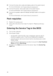
... Connect the power-status light cable to appear, press F2 key on the computer. 2 Enter System Setup: - Entering the Service Tag in the BIOS 1 Turn on your keyboard immediately. - press the power and volume-up button to launch the One Time Boot Menu and select Enter Setup . 3 Navigate to the system board. during POST, when the DELL logo is displayed, watch for the F2 prompt to the system board. 13 Connect the hard-drive cable and display cable...
... Connect the power-status light cable to appear, press F2 key on the computer. 2 Enter System Setup: - Entering the Service Tag in the BIOS 1 Turn on your keyboard immediately. - press the power and volume-up button to launch the One Time Boot Menu and select Enter Setup . 3 Navigate to the system board. during POST, when the DELL logo is displayed, watch for the F2 prompt to the system board. 13 Connect the hard-drive cable and display cable...


