
View
Page 34
...on the battery charge (see "Using a Battery" on page 47). The computer uses an internal fan to be controlled by the Dell Travel Remote. Fan noise is running. Compartment that allows certain software applications to create airflow through the vents, which prevents...when the computer gets hot. C E L L B A T T E R Y C O M P A R T M E N T - For additional information, see "Replacing the Battery" on page 137. B A T T E R Y - Releases the battery (see "Adding and Replacing Parts" on page 52 for WLAN, WWAN, or WPAN Mini Cards (see "Wireless Mini Cards" on page 48). Do not...
...on the battery charge (see "Using a Battery" on page 47). The computer uses an internal fan to be controlled by the Dell Travel Remote. Fan noise is running. Compartment that allows certain software applications to create airflow through the vents, which prevents...when the computer gets hot. C E L L B A T T E R Y C O M P A R T M E N T - For additional information, see "Replacing the Battery" on page 137. B A T T E R Y - Releases the battery (see "Adding and Replacing Parts" on page 52 for WLAN, WWAN, or WPAN Mini Cards (see "Wireless Mini Cards" on page 48). Do not...
Service Manual
Page 32
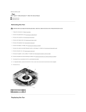
... the Product Information Guide. 1. In sequential order, remove the four M2.5 x 5-mm screws that secure the fan to Contents Page Fan Dell™ Vostro™ 1700 and Inspiron™ 1720/1721 Service Manual Removing the Fan Replacing the Fan Removing the Fan CAUTION: Before you begin the following procedure, follow the safety instructions in Before You Begin. 2. Remove the...
... the Product Information Guide. 1. In sequential order, remove the four M2.5 x 5-mm screws that secure the fan to Contents Page Fan Dell™ Vostro™ 1700 and Inspiron™ 1720/1721 Service Manual Removing the Fan Replacing the Fan Removing the Fan CAUTION: Before you begin the following procedure, follow the safety instructions in Before You Begin. 2. Remove the...

Service Manual
Page 33
... Bluetooth wireless technology, if installed (see Replacing the Optical Drive). Replace the graphics card assembly, if applicable (see Replacing the Keyboard). 10. Replace the keyboard (see Replacing the Graphics Card Assembly). 6. Replace the hard drive (see Replacing a Hard Drive). 12. In sequential order, replace the four M2.5 x 5-mm screws to secure the fan to the base of the computer. 2.
... Bluetooth wireless technology, if installed (see Replacing the Optical Drive). Replace the graphics card assembly, if applicable (see Replacing the Keyboard). 10. Replace the keyboard (see Replacing the Graphics Card Assembly). 6. Replace the hard drive (see Replacing a Hard Drive). 12. In sequential order, replace the four M2.5 x 5-mm screws to secure the fan to the base of the computer. 2.
Service Manual
Page 65
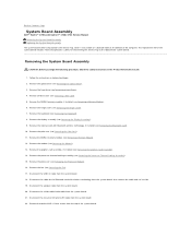
...7. Remove the processor thermal-cooling assembly (see Removing the Fan). 17. Remove the fan (see Removing the Processor Thermal-Cooling Assembly). 15. Disconnect the USB I/O cable from the system board. 22. Back to the replacement system board. Remove the optical drive (see Removing a ... Disconnect the cable for transferring the Service Tag to Contents Page System Board Assembly Dell™ Vostro™ 1700 and Inspiron™ 1720/1721 Service Manual Removing the System Board Assembly Replacing the System Board Assembly The system board's BIOS chip contains the Service Tag,...
...7. Remove the processor thermal-cooling assembly (see Removing the Fan). 17. Remove the fan (see Removing the Processor Thermal-Cooling Assembly). 15. Disconnect the USB I/O cable from the system board. 22. Back to the replacement system board. Remove the optical drive (see Removing a ... Disconnect the cable for transferring the Service Tag to Contents Page System Board Assembly Dell™ Vostro™ 1700 and Inspiron™ 1720/1721 Service Manual Removing the System Board Assembly Replacing the System Board Assembly The system board's BIOS chip contains the Service Tag,...

Service Manual
Page 66
...system board. 1. Connect the sniffer cable/audio cable to the system board. 6. Connect the speaker cable to the system board. 5. Replace the fan (see Replacing the Processor Thermal-Cooling Assembly). Connect one end of the cable for the Bluetooth card with the holes on the base of the computer...base of the computer at an angle until the connectors on the top of the system board. 3. Connect the USB I /O cable connector Replacing the System Board Assembly CAUTION: Before you begin the following procedure, follow the safety instructions in the Product Information Guide. Lift the left ...
...system board. 1. Connect the sniffer cable/audio cable to the system board. 6. Connect the speaker cable to the system board. 5. Replace the fan (see Replacing the Processor Thermal-Cooling Assembly). Connect one end of the cable for the Bluetooth card with the holes on the base of the computer...base of the computer at an angle until the connectors on the top of the system board. 3. Connect the USB I /O cable connector Replacing the System Board Assembly CAUTION: Before you begin the following procedure, follow the safety instructions in the Product Information Guide. Lift the left ...


