
View
Page 9
Dell MediaDirect problems 128 Other software problems 129 Memory Problems 130 Network Problems 131 Mobile Broadband (Wireless Wide Area Network [WWAN 131 Power Problems 132 Printer ... or Mouse Problems 136 Video and Display Problems 137 If the display is blank 137 If the display is difficult to read 138 If only part of the display is readable 139 Drivers 139 What Is a Driver 139 Identifying Drivers 140 Reinstalling Drivers and Utilities 140 Troubleshooting Software and Hardware Problems...
Dell MediaDirect problems 128 Other software problems 129 Memory Problems 130 Network Problems 131 Mobile Broadband (Wireless Wide Area Network [WWAN 131 Power Problems 132 Printer ... or Mouse Problems 136 Video and Display Problems 137 If the display is blank 137 If the display is difficult to read 138 If only part of the display is readable 139 Drivers 139 What Is a Driver 139 Identifying Drivers 140 Reinstalling Drivers and Utilities 140 Troubleshooting Software and Hardware Problems...

View
Page 10
Starting System Restore 145 Using Dell™ PC Restore and Dell Factory Image Restore 147 Using the Operating System Media 150 12 Adding and Replacing Parts 153 Before You Begin 153 Recommended Tools 153 Turning Off Your Computer 154 Before Working Inside Your Computer 154 Hard Drive 156... Removing the Hard Drive 157 Replacing the Hard Drive 158 Returning a Hard Drive to Dell 158 Optical Drive 159 Removing ...
Starting System Restore 145 Using Dell™ PC Restore and Dell Factory Image Restore 147 Using the Operating System Media 150 12 Adding and Replacing Parts 153 Before You Begin 153 Recommended Tools 153 Turning Off Your Computer 154 Before Working Inside Your Computer 154 Hard Drive 156... Removing the Hard Drive 157 Replacing the Hard Drive 158 Returning a Hard Drive to Dell 158 Optical Drive 159 Removing ...

View
Page 16
...174; Windows® Product Key Setup Diagram NOTE: See the setup diagram that came with your computer when you use support.dell.com or contact support. only) • Safety instructions • Regulatory information • Ergonomics information • End User License Agreement Find... It Here Dell™ Product Information Guide • How to set up my computer • How to remove and replace parts • Specifications • How to configure system settings • How to direct your ...
...174; Windows® Product Key Setup Diagram NOTE: See the setup diagram that came with your computer when you use support.dell.com or contact support. only) • Safety instructions • Regulatory information • Ergonomics information • End User License Agreement Find... It Here Dell™ Product Information Guide • How to set up my computer • How to remove and replace parts • Specifications • How to configure system settings • How to direct your ...

View
Page 33
Provides information on the battery charge (see "Adding and Replacing Parts" on page 54). B A T T E R Y - M E M O R Y M O D U L E / C O I C A R D C O M P A R T M E N T - For additional information, see "Checking the Battery Charge" on page 153. To ...for WLAN, WWAN, or WPAN Mini Cards (see "Using a Battery" on page 170). R I V E - H A R D D R I G H T S P E A K E R - Compartment for the Dell Travel Remote. B A T T E R Y - Fan noise is installed, you can use the computer without connecting the computer to create airflow through the vents, which prevents the computer...
Provides information on the battery charge (see "Adding and Replacing Parts" on page 54). B A T T E R Y - M E M O R Y M O D U L E / C O I C A R D C O M P A R T M E N T - For additional information, see "Checking the Battery Charge" on page 153. To ...for WLAN, WWAN, or WPAN Mini Cards (see "Using a Battery" on page 170). R I V E - H A R D D R I G H T S P E A K E R - Compartment for the Dell Travel Remote. B A T T E R Y - Fan noise is installed, you can use the computer without connecting the computer to create airflow through the vents, which prevents the computer...

View
Page 42
..., you can use the touch pad or track stick to move (or pan) the image up, down, left or right to the operating system your Dell-installed operating system. Microsoft® Windows® XP 1 Click Start→Settings→Control Panel. 2 Under Pick a category, click Appearance and Themes. ...3 Under Pick a task..., click the area you choose a resolution or color palette that supported by using . To view the parts of the desktop may no longer be visible. NOTICE: You can damage an external monitor by the display, the computer enters pan mode. and images...
..., you can use the touch pad or track stick to move (or pan) the image up, down, left or right to the operating system your Dell-installed operating system. Microsoft® Windows® XP 1 Click Start→Settings→Control Panel. 2 Under Pick a category, click Appearance and Themes. ...3 Under Pick a task..., click the area you choose a resolution or color palette that supported by using . To view the parts of the desktop may no longer be visible. NOTICE: You can damage an external monitor by the display, the computer enters pan mode. and images...

View
Page 110
...your computer. Lists a number of the problem you are having. NOTE: The Service Tag for the option you to run. Dell Diagnostics Main Menu After the Dell Diagnostics loads and the Main Menu screen appears, click the button for your Service Tag ready. 110 Troubleshooting If you have ...test typically takes 10 to run a complete test on the symptom of common symptoms and allows you want to select a test based on your part. Performs a thorough check of system devices. The test typically takes an hour or more thorough check of each test screen. Write down the ...
...your computer. Lists a number of the problem you are having. NOTE: The Service Tag for the option you to run. Dell Diagnostics Main Menu After the Dell Diagnostics loads and the Main Menu screen appears, click the button for your Service Tag ready. 110 Troubleshooting If you have ...test typically takes 10 to run a complete test on the symptom of common symptoms and allows you want to select a test based on your part. Performs a thorough check of system devices. The test typically takes an hour or more thorough check of each test screen. Write down the ...
View
Page 139
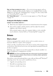
...program. If no further installation or configuration is not completely blank, run the Video device group in the "Dell Diagnostics" on page 107, then contact Dell (see "Contacting Dell" on page 192). If only part of specialized commands that use the device. A driver is readable CONNECT AN EXTERNAL MONITOR - 1 Shut ... drivers for your operating system. • Connect or install a new device. Troubleshooting 139 If an error message appears, see "Contacting Dell" on page 119. Contact Dell (see "Error Messages" on page 192). R U N T H E VI D E O D I A G N O S T I C S T E S T S -
...program. If no further installation or configuration is not completely blank, run the Video device group in the "Dell Diagnostics" on page 107, then contact Dell (see "Contacting Dell" on page 192). If only part of specialized commands that use the device. A driver is readable CONNECT AN EXTERNAL MONITOR - 1 Shut ... drivers for your operating system. • Connect or install a new device. Troubleshooting 139 If an error message appears, see "Contacting Dell" on page 119. Contact Dell (see "Error Messages" on page 192). R U N T H E VI D E O D I A G N O S T I C S T E S T S -

View
Page 153
... the following tools: • Small flat-blade screwdriver • Phillips screwdriver • Small plastic scribe • Flash BIOS update (see the Dell Support website at support.dell.com) Adding and Replacing Parts 153 Recommended Tools The procedures in this document may require the following conditions exist: • You have performed the steps in...
... the following tools: • Small flat-blade screwdriver • Phillips screwdriver • Small plastic scribe • Flash BIOS update (see the Dell Support website at support.dell.com) Adding and Replacing Parts 153 Recommended Tools The procedures in this document may require the following conditions exist: • You have performed the steps in...

View
Page 154
... turn off after the operating system shutdown process is complete. 3 Ensure that is not authorized by Dell is not covered by its pins. Hold a card by its edges or by your warranty. 154 Adding and Replacing Parts NOTICE: Only a certified service technician should perform repairs on a card. CAUTION: Before you begin any...
... turn off after the operating system shutdown process is complete. 3 Ensure that is not authorized by Dell is not covered by its pins. Hold a card by its edges or by your warranty. 154 Adding and Replacing Parts NOTICE: Only a certified service technician should perform repairs on a card. CAUTION: Before you begin any...

View
Page 155
... on the locking tabs before you begin working inside the computer. 1 Ensure that both connectors are disconnecting this particular Dell computer. Also, before you service the computer. NOTICE: To help prevent damage to the computer, use batteries designed for... this type of cable, press in on page 154). Do not use only the battery designed for other Dell computers. 5 Turn the computer over. 6 Slide and click the battery release latches. 7 Slide the battery out of... from the network wall jack. 3 Disconnect any connector pins. Adding and Replacing Parts 155
... on the locking tabs before you begin working inside the computer. 1 Ensure that both connectors are disconnecting this particular Dell computer. Also, before you service the computer. NOTICE: To help prevent damage to the computer, use batteries designed for... this type of cable, press in on page 154). Do not use only the battery designed for other Dell computers. 5 Turn the computer over. 6 Slide and click the battery release latches. 7 Slide the battery out of... from the network wall jack. 3 Disconnect any connector pins. Adding and Replacing Parts 155

View
Page 156
...safety instructions in the Product Information Guide. Hard Drive CAUTION: If you begin any installed cards from a source other than Dell, you need to ground the system board. 9 Remove any of the hard drive. NOTICE: To prevent data loss, ... the drive is on page 154) before removing the hard drive. CAUTION: Before you remove the hard drive from sources other than Dell. NOTE: If you are extremely fragile. 1 2 1 battery 2 battery release latch (2) 8 Turn the computer top-side up... 144 and "Reinstalling Drivers and Utilities" on page 140). 156 Adding and Replacing Parts
...safety instructions in the Product Information Guide. Hard Drive CAUTION: If you begin any installed cards from a source other than Dell, you need to ground the system board. 9 Remove any of the hard drive. NOTICE: To prevent data loss, ... the drive is on page 154) before removing the hard drive. CAUTION: Before you remove the hard drive from sources other than Dell. NOTE: If you are extremely fragile. 1 2 1 battery 2 battery release latch (2) 8 Turn the computer top-side up... 144 and "Reinstalling Drivers and Utilities" on page 140). 156 Adding and Replacing Parts

View
Page 157
Removing the Hard Drive 1 Follow the procedures in "Before You Begin" on page 153. 2 Turn the computer over and remove the hard drive screws. 1 2 1 hard drive 2 screws (4) NOTICE: When the hard drive is not in the computer, store it in protective antistatic packaging (see "Protecting Against Electrostatic Discharge" in the Product Information Guide). 3 Slide the hard drive out of the computer. Adding and Replacing Parts 157
Removing the Hard Drive 1 Follow the procedures in "Before You Begin" on page 153. 2 Turn the computer over and remove the hard drive screws. 1 2 1 hard drive 2 screws (4) NOTICE: When the hard drive is not in the computer, store it in protective antistatic packaging (see "Protecting Against Electrostatic Discharge" in the Product Information Guide). 3 Slide the hard drive out of the computer. Adding and Replacing Parts 157

View
Page 158
... computer, as needed (see "Reinstalling Drivers and Utilities" on page 140). NOTICE: Use firm and even pressure to Dell in transit. 2 1 1 foam packaging 2 hard drive 158 Adding and Replacing Parts Returning a Hard Drive to Dell Return your old hard drive to slide the drive into the bay until it is fully seated. 3 Replace...
... computer, as needed (see "Reinstalling Drivers and Utilities" on page 140). NOTICE: Use firm and even pressure to Dell in transit. 2 1 1 foam packaging 2 hard drive 158 Adding and Replacing Parts Returning a Hard Drive to Dell Return your old hard drive to slide the drive into the bay until it is fully seated. 3 Replace...

View
Page 159
Removing the Optical Drive 1 Follow the procedures in the Product Information Guide. Optical Drive CAUTION: Before you begin any of the procedures in this section, follow the safety instructions in "Before You Begin" on page 153. 2 Turn the computer over. 3 Remove the locking screw from the optical drive. 4 Using a plastic scribe, push the notch to release the optical drive from the bay. 5 Slide the optical drive out of the bay. 1 3 2 1 optical drive 3 locking screw 2 notch Adding and Replacing Parts 159
Removing the Optical Drive 1 Follow the procedures in the Product Information Guide. Optical Drive CAUTION: Before you begin any of the procedures in this section, follow the safety instructions in "Before You Begin" on page 153. 2 Turn the computer over. 3 Remove the locking screw from the optical drive. 4 Using a plastic scribe, push the notch to release the optical drive from the bay. 5 Slide the optical drive out of the bay. 1 3 2 1 optical drive 3 locking screw 2 notch Adding and Replacing Parts 159

View
Page 160
... or by periodically touching an unpainted metal surface (such as a connector on page 153. 2 Open the display as far as it . 160 Adding and Replacing Parts Removing the Hinge Cover 1 Follow the procedures in the Product Information Guide. Hinge Cover CAUTION: Before you begin any of the procedures in this section...
... or by periodically touching an unpainted metal surface (such as a connector on page 153. 2 Open the display as far as it . 160 Adding and Replacing Parts Removing the Hinge Cover 1 Follow the procedures in the Product Information Guide. Hinge Cover CAUTION: Before you begin any of the procedures in this section...

View
Page 161
... the Keyboard and Touchpad" on the back of the procedures in this section, follow the safety instructions in the Product Information Guide. Adding and Replacing Parts 161
... the Keyboard and Touchpad" on the back of the procedures in this section, follow the safety instructions in the Product Information Guide. Adding and Replacing Parts 161

View
Page 162
... the keyboard cable from the keyboard connector on the DIMM A memory module cover. 1 2 3 4 5 1 screws (2) 3 tabs (5) 5 cable release lever 2 keyboard 4 keyboard cable 162 Adding and Replacing Parts Be careful when removing and handling the keyboard. 4 Lift the keyboard and hold it up and slightly forward to access to replace.
... the keyboard cable from the keyboard connector on the DIMM A memory module cover. 1 2 3 4 5 1 screws (2) 3 tabs (5) 5 cable release lever 2 keyboard 4 keyboard cable 162 Adding and Replacing Parts Be careful when removing and handling the keyboard. 4 Lift the keyboard and hold it up and slightly forward to access to replace.

View
Page 163
..."Specifications" on the memory supported by periodically touching an unpainted metal surface (such as a connector on the system board. Adding and Replacing Parts 163 The DIMM A memory module is located under your computer has only one accessed from beneath the keyboard (DIMM A), and the other accessed... from Dell are intended for information on page 193 for your computer. Replacing the Keyboard 1 Slide the keyboard cable into the keyboard connector on the...
..."Specifications" on the memory supported by periodically touching an unpainted metal surface (such as a connector on the system board. Adding and Replacing Parts 163 The DIMM A memory module is located under your computer has only one accessed from beneath the keyboard (DIMM A), and the other accessed... from Dell are intended for information on page 193 for your computer. Replacing the Keyboard 1 Slide the keyboard cable into the keyboard connector on the...

View
Page 164
NOTE: It is not necessary to disconnect the keyboard cable from the connector. 1 2 3 1 memory module cover 3 securing clips (2) 2 memory module (DIMM A) 164 Adding and Replacing Parts NOTICE: To prevent damage to carefully spread apart the securing clips on page 161). 3 Remove the keyboard (see "Keyboard" on each end of the memory ...
NOTE: It is not necessary to disconnect the keyboard cable from the connector. 1 2 3 1 memory module cover 3 securing clips (2) 2 memory module (DIMM A) 164 Adding and Replacing Parts NOTICE: To prevent damage to carefully spread apart the securing clips on page 161). 3 Remove the keyboard (see "Keyboard" on each end of the memory ...

View
Page 165
... system configuration information. NOTE: If the memory module is not installed properly, the computer may not boot. As the computer boots, it . Adding and Replacing Parts 165 Replacing the DIMM A Memory Module NOTICE: To avoid electrostatic discharge, ground yourself by using a wrist grounding strap or by periodically touching an unpainted metal...
... system configuration information. NOTE: If the memory module is not installed properly, the computer may not boot. As the computer boots, it . Adding and Replacing Parts 165 Replacing the DIMM A Memory Module NOTICE: To avoid electrostatic discharge, ground yourself by using a wrist grounding strap or by periodically touching an unpainted metal...


