
Service Manual
Page 4
Replacing the Hard Drive 24 6 Optical Drive 25 Removing the Optical Drive 25 Replacing the Optical Drive 26 7 Memory Module(s 29 Removing the Memory Module(s 29 Replacing the Memory Module(s 31 8 Base Cover 33 Removing the Base Cover 33 Replacing the Base Cover 34 9 Wireless Mini-Card 35 Removing the Mini-Card 35 Replacing the Mini-Card 37 10 Processor Fan and Heat Sink Assembly 39 Removing the Processor Fan and Heat Sink Assembly . 39 Replacing the Processor Fan and Heat Sink Assembly . 41 4 Contents
Replacing the Hard Drive 24 6 Optical Drive 25 Removing the Optical Drive 25 Replacing the Optical Drive 26 7 Memory Module(s 29 Removing the Memory Module(s 29 Replacing the Memory Module(s 31 8 Base Cover 33 Removing the Base Cover 33 Replacing the Base Cover 34 9 Wireless Mini-Card 35 Removing the Mini-Card 35 Replacing the Mini-Card 37 10 Processor Fan and Heat Sink Assembly 39 Removing the Processor Fan and Heat Sink Assembly . 39 Replacing the Processor Fan and Heat Sink Assembly . 41 4 Contents
Service Manual
Page 5
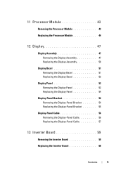
...Module 43 Removing the Processor Module 43 Replacing the Processor Module 44 12 Display 47 Display Assembly 47 Removing the Display Assembly 47 Replacing the Display Assembly 50 Display Bezel 51 Removing the Display Bezel 51 Replacing the Display Bezel 52 Display Panel 53 Removing the Display Panel 53 Replacing the Display Panel 54 Display-Panel Bracket 54 Removing the Display-Panel Bracket 54 Replacing the Display-Panel Bracket 55 Display-Panel Cable 56 Removing the Display-Panel Cable 56 Replacing the Display-Panel Cable 57 13 Inverter Board 59 Removing the Inverter Board...
...Module 43 Removing the Processor Module 43 Replacing the Processor Module 44 12 Display 47 Display Assembly 47 Removing the Display Assembly 47 Replacing the Display Assembly 50 Display Bezel 51 Removing the Display Bezel 51 Replacing the Display Bezel 52 Display Panel 53 Removing the Display Panel 53 Replacing the Display Panel 54 Display-Panel Bracket 54 Removing the Display-Panel Bracket 54 Replacing the Display-Panel Bracket 55 Display-Panel Cable 56 Removing the Display-Panel Cable 56 Replacing the Display-Panel Cable 57 13 Inverter Board 59 Removing the Inverter Board...
Service Manual
Page 6
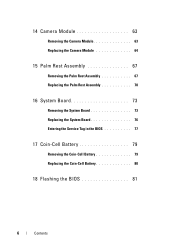
14 Camera Module 63 Removing the Camera Module 63 Replacing the Camera Module 64 15 Palm Rest Assembly 67 Removing the Palm Rest Assembly 67 Replacing the Palm Rest Assembly 70 16 System Board 73 Removing the System Board 73 Replacing the System Board 76 Entering the Service Tag in the BIOS 77 17 Coin-Cell Battery 79 Removing the Coin-Cell Battery 79 Replacing the Coin-Cell Battery 80 18 Flashing the BIOS 81 6 Contents
14 Camera Module 63 Removing the Camera Module 63 Replacing the Camera Module 64 15 Palm Rest Assembly 67 Removing the Palm Rest Assembly 67 Replacing the Palm Rest Assembly 70 16 System Board 73 Removing the System Board 73 Replacing the System Board 76 Entering the Service Tag in the BIOS 77 17 Coin-Cell Battery 79 Removing the Coin-Cell Battery 79 Replacing the Coin-Cell Battery 80 18 Flashing the BIOS 81 6 Contents
Service Manual
Page 9
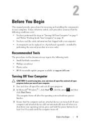
... attached devices are turned off. Before You Begin 9 2 Before You Begin This manual provides procedures for at support.dell.com Turning Off Your Computer CAUTION: To avoid losing data, save and close all open files and exit all open programs. 2 In Microsoft® Windows® 7, click Start click Shut Down. , click the arrow , and then The computer turns off after the operating...
... attached devices are turned off. Before You Begin 9 2 Before You Begin This manual provides procedures for at support.dell.com Turning Off Your Computer CAUTION: To avoid losing data, save and close all open files and exit all open programs. 2 In Microsoft® Windows® 7, click Start click Shut Down. , click the arrow , and then The computer turns off after the operating...
Service Manual
Page 10
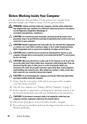
... unpainted metal surface (such as a processor module by its edges, not by its pins. Some cables have connectors with care. if you connect a cable, ensure that both connectors are disconnecting this type of cable, press in -1 Media Card Reader. 10 Before You Begin Before Working Inside Your Computer Use the following steps before you begin working inside the computer. 1 Ensure that the...
... unpainted metal surface (such as a processor module by its edges, not by its pins. Some cables have connectors with care. if you connect a cable, ensure that both connectors are disconnecting this type of cable, press in -1 Media Card Reader. 10 Before You Begin Before Working Inside Your Computer Use the following steps before you begin working inside the computer. 1 Ensure that the...
Service Manual
Page 11
6 Disconnect your computer and all attached devices from their electrical outlets. Before You Begin 11 CAUTION: To help prevent damage to the system board, remove the main battery (see "Removing the Battery" on page 13) before working inside the computer. 7 Remove the battery (see "Removing the Battery" on page 13). 8 Turn the computer top-side up, open the display, and press the power button to ground the system board.
6 Disconnect your computer and all attached devices from their electrical outlets. Before You Begin 11 CAUTION: To help prevent damage to the system board, remove the main battery (see "Removing the Battery" on page 13) before working inside the computer. 7 Remove the battery (see "Removing the Battery" on page 13). 8 Turn the computer top-side up, open the display, and press the power button to ground the system board.
Service Manual
Page 21
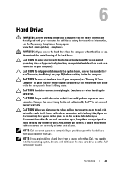
... remove the hard drive while the computer is hot, do not touch the metal housing of cable, press in Sleep state. CAUTION: Hard drives are installing a hard drive from sources other than Dell. NOTE: Dell does not guarantee compatibility or provide support for hard drives from a source other than Dell, you disconnect the cable. CAUTION: When you pull connectors apart, keep them evenly aligned to install an operating system, drivers, and utilities on the cable...
... remove the hard drive while the computer is hot, do not touch the metal housing of cable, press in Sleep state. CAUTION: Hard drives are installing a hard drive from sources other than Dell. NOTE: Dell does not guarantee compatibility or provide support for hard drives from a source other than Dell, you disconnect the cable. CAUTION: When you pull connectors apart, keep them evenly aligned to install an operating system, drivers, and utilities on the cable...
Service Manual
Page 24
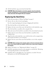
... "Restoring Your Operating System" in the Setup Guide). 12 Install the drivers and utilities for storing or shipping the hard drive. 3 Place the hard drive in the hard-drive cage. 4 Replace the four screws that secure the hard-drive assembly to the computer base. 8 Align the tabs on the hard-drive cover with your computer, as needed . Failure to do so may result in the computer base. 6 Slide and connect the hard-drive...
... "Restoring Your Operating System" in the Setup Guide). 12 Install the drivers and utilities for storing or shipping the hard drive. 3 Place the hard drive in the hard-drive cage. 4 Replace the four screws that secure the hard-drive assembly to the computer base. 8 Align the tabs on the hard-drive cover with your computer, as needed . Failure to do so may result in the computer base. 6 Slide and connect the hard-drive...
Service Manual
Page 29
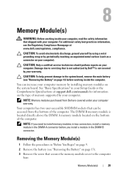
... by using a wrist grounding strap or by your Setup Guide or the Comprehensive Specifications at www.dell.com/regulatory_compliance. See "Basic Specifications" in the DIMM A connector before working inside the computer. For additional safety best practices information, see "Removing the Battery" on page 13). 3 Remove the screw that secures the memory-module cover to servicing that can increase your computer. NOTE: If you install a module in...
... by using a wrist grounding strap or by your Setup Guide or the Comprehensive Specifications at www.dell.com/regulatory_compliance. See "Basic Specifications" in the DIMM A connector before working inside the computer. For additional safety best practices information, see "Removing the Battery" on page 13). 3 Remove the screw that secures the memory-module cover to servicing that can increase your computer. NOTE: If you install a module in...
Service Manual
Page 31
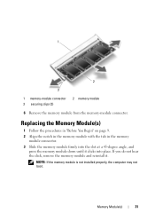
... the memory module is not installed properly, the computer may not boot. If you do not hear the click, remove the memory module and reinstall it clicks into place. 1 2 3 1 memory-module connector 3 securing clips (2) 2 memory module 6 Remove the memory module from the memory-module connector. Replacing the Memory Module(s) 1 Follow the procedures in "Before You Begin" on page 9. 2 Align the notch in the memory module with the tab in the memory module connector...
... the memory module is not installed properly, the computer may not boot. If you do not hear the click, remove the memory module and reinstall it clicks into place. 1 2 3 1 memory-module connector 3 securing clips (2) 2 memory module 6 Remove the memory module from the memory-module connector. Replacing the Memory Module(s) 1 Follow the procedures in "Before You Begin" on page 9. 2 Align the notch in the memory module with the tab in the memory module connector...
Service Manual
Page 32
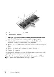
... updates the system configuration information. To confirm the amount of memory installed in position. 5 Replace the screw that secures the memory module cover to close may damage your computer. 4 Align the tabs on the memory module cover with the slots on the computer. As the computer boots, it . 3 2 1 1 tab 2 notch 3 memory-module connector CAUTION: If the memory module cover is difficult to the computer base. 6 Replace the battery (see "Replacing the Battery...
... updates the system configuration information. To confirm the amount of memory installed in position. 5 Replace the screw that secures the memory module cover to close may damage your computer. 4 Align the tabs on the memory module cover with the slots on the computer. As the computer boots, it . 3 2 1 1 tab 2 notch 3 memory-module connector CAUTION: If the memory module cover is difficult to the computer base. 6 Replace the battery (see "Replacing the Battery...
Service Manual
Page 37
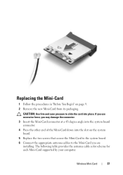
... the system board connector. 4 Press the other end of the Mini-Card down into place. Wireless Mini-Card 37 Replacing the Mini-Card 1 Follow the procedures in "Before You Begin" on the system board. 5 Replace the two screws that secure the Mini-Card to the system board. 6 Connect the appropriate antenna cables to slide the card into the slot on page 9. 2 Remove the new Mini-Card from...
... the system board connector. 4 Press the other end of the Mini-Card down into place. Wireless Mini-Card 37 Replacing the Mini-Card 1 Follow the procedures in "Before You Begin" on the system board. 5 Replace the two screws that secure the Mini-Card to the system board. 6 Connect the appropriate antenna cables to slide the card into the slot on page 9. 2 Remove the new Mini-Card from...
Service Manual
Page 38
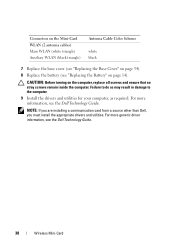
... Dell Technology Guide. CAUTION: Before turning on page 14). Failure to do so may result in damage to the computer. 9 Install the drivers and utilities for your computer, as required. Connectors on the Mini-Card WLAN (2 antenna cables) Main WLAN (white triangle) Auxiliary WLAN (black triangle) Antenna Cable Color Scheme white black 7 Replace the base cover (see "Replacing the Base Cover" on page 34). 8 Replace the battery...
... Dell Technology Guide. CAUTION: Before turning on page 14). Failure to do so may result in damage to the computer. 9 Install the drivers and utilities for your computer, as required. Connectors on the Mini-Card WLAN (2 antenna cables) Main WLAN (white triangle) Auxiliary WLAN (black triangle) Antenna Cable Color Scheme white black 7 Replace the base cover (see "Replacing the Base Cover" on page 34). 8 Replace the battery...
Service Manual
Page 43
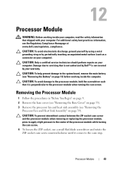
... system board, remove the main battery (see "Removing the Battery" on page 13) before working inside the computer. CAUTION: To avoid electrostatic discharge, ground yourself by using a wrist grounding strap or by periodically touching an unpainted metal surface (such as a connector on page 33). 3 Remove the processor fan and heat sink assembly (see the Regulatory Compliance Homepage at www.dell.com...
... system board, remove the main battery (see "Removing the Battery" on page 13) before working inside the computer. CAUTION: To avoid electrostatic discharge, ground yourself by using a wrist grounding strap or by periodically touching an unpainted metal surface (such as a connector on page 33). 3 Remove the processor fan and heat sink assembly (see the Regulatory Compliance Homepage at www.dell.com...
Service Manual
Page 44
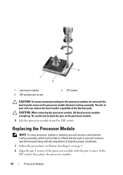
...the processor module. 44 Processor Module Replacing the Processor Module NOTE: If a new processor module is installed, you will receive a new thermalcooling assembly, which will include an affixed thermal pad, or you will receive a new thermal pad along with the pin-1 corner of the thermal pads. The ...module, do not touch the heat transfer areas on page 9. 2 Align the pin-1 corner of the processor module with documentation to bend the pins on the processor module. 5 Lift the processor module from the ZIF socket. CAUTION: When removing the processor module, lift the processor module...
...the processor module. 44 Processor Module Replacing the Processor Module NOTE: If a new processor module is installed, you will receive a new thermalcooling assembly, which will include an affixed thermal pad, or you will receive a new thermal pad along with the pin-1 corner of the thermal pads. The ...module, do not touch the heat transfer areas on page 9. 2 Align the pin-1 corner of the processor module with documentation to bend the pins on the processor module. 5 Lift the processor module from the ZIF socket. CAUTION: When removing the processor module, lift the processor module...
Service Manual
Page 51
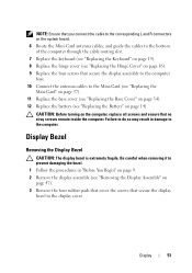
... removing it to prevent damaging the bezel. 1 Follow the procedures in damage to the computer. NOTE: Ensure that you connect the cable to the corresponding L and R connectors on the system board. 6 Route the Mini-Card antenna cables, and guide the cables to the bottom of the computer through the cable routing slot. 7 Replace the keyboard (see "Replacing the Keyboard" on page 19). 8 Replace the hinge cover...
... removing it to prevent damaging the bezel. 1 Follow the procedures in damage to the computer. NOTE: Ensure that you connect the cable to the corresponding L and R connectors on the system board. 6 Route the Mini-Card antenna cables, and guide the cables to the bottom of the computer through the cable routing slot. 7 Replace the keyboard (see "Replacing the Keyboard" on page 19). 8 Replace the hinge cover...
Service Manual
Page 63
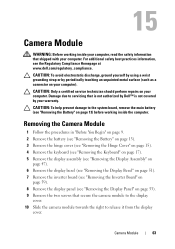
... Cover" on page 15). 4 Remove the keyboard (see "Removing the Keyboard" on page 17). 5 Remove the display assembly (see "Removing the Display Assembly" on page 47). 6 Remove the display bezel (see "Removing the Display Bezel" on page 51). 7 Remove the inverter board (see "Removing the Inverter Board" on page 59). 8 Remove the display panel (see the Regulatory Compliance Homepage at www.dell.com/regulatory_compliance. Camera Module 63 CAUTION: Only a certified service technician should perform repairs...
... Cover" on page 15). 4 Remove the keyboard (see "Removing the Keyboard" on page 17). 5 Remove the display assembly (see "Removing the Display Assembly" on page 47). 6 Remove the display bezel (see "Removing the Display Bezel" on page 51). 7 Remove the inverter board (see "Removing the Inverter Board" on page 59). 8 Remove the display panel (see the Regulatory Compliance Homepage at www.dell.com/regulatory_compliance. Camera Module 63 CAUTION: Only a certified service technician should perform repairs...
Service Manual
Page 64
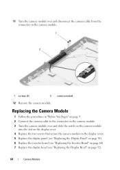
... the camera module. 3 Turn the camera module over and disconnect the camera cable from the connector on page 52). 64 Camera Module Replacing the Camera Module 1 Follow the procedures in "Before You Begin" on page 9. 2 Connect the camera cable to the display cover. 5 Replace the display panel (see "Replacing the Display Panel" on page 54). 6 Replace the inverter board (see "Replacing the Inverter Board" on page 60). 7 Replace the display bezel (see "Replacing the Display Bezel" on the camera module. 1 2 1 screws (2) 2 camera module 12 Remove the camera module.
... the camera module. 3 Turn the camera module over and disconnect the camera cable from the connector on page 52). 64 Camera Module Replacing the Camera Module 1 Follow the procedures in "Before You Begin" on page 9. 2 Connect the camera cable to the display cover. 5 Replace the display panel (see "Replacing the Display Panel" on page 54). 6 Replace the inverter board (see "Replacing the Inverter Board" on page 60). 7 Replace the display bezel (see "Replacing the Display Bezel" on the camera module. 1 2 1 screws (2) 2 camera module 12 Remove the camera module.
Service Manual
Page 74
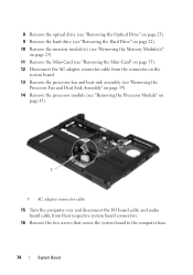
8 Remove the optical drive (see "Removing the Optical Drive" on page 25). 9 Remove the hard drive (see "Removing the Hard Drive" on page 22). 10 Remove the memory module(s) (see "Removing the Memory Module(s)" on page 29). 11 Remove the Mini-Card (see "Removing the Mini-Card" on page 35). 12 Disconnect the AC adapter connector cable from the connector on the system board. 13 Remove the processor fan and heat sink assembly (see "Removing the Processor...
8 Remove the optical drive (see "Removing the Optical Drive" on page 25). 9 Remove the hard drive (see "Removing the Hard Drive" on page 22). 10 Remove the memory module(s) (see "Removing the Memory Module(s)" on page 29). 11 Remove the Mini-Card (see "Removing the Mini-Card" on page 35). 12 Disconnect the AC adapter connector cable from the connector on the system board. 13 Remove the processor fan and heat sink assembly (see "Removing the Processor...
Service Manual
Page 77
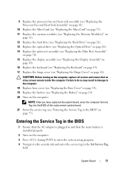
... Cover" on page 34). 19 Replace the battery (see "Replacing the Battery" on page 14). 20 Turn on the computer. 9 Replace the processor fan and heat sink assembly (see "Replacing the Processor Fan and Heat Sink Assembly" on page 41). 10 Replace the Mini-Card (see "Replacing the Mini-Card" on page 37). 11 Replace the memory modules (see "Replacing the Memory Module(s)" on page 31). 12 Replace the hard drive (see "Replacing the Hard Drive...
... Cover" on page 34). 19 Replace the battery (see "Replacing the Battery" on page 14). 20 Turn on the computer. 9 Replace the processor fan and heat sink assembly (see "Replacing the Processor Fan and Heat Sink Assembly" on page 41). 10 Replace the Mini-Card (see "Replacing the Mini-Card" on page 37). 11 Replace the memory modules (see "Replacing the Memory Module(s)" on page 31). 12 Replace the hard drive (see "Replacing the Hard Drive...


