
Owner's Manual
Page 10
... the Hard Drive 133 Returning a Hard Drive to Dell 134 Optical Drive 134 Removing the Optical Drive 134 Replacing the Optical Drive 135 Hinge Cover 135 Removing the Hinge Cover 136 Replacing the Hinge Cover 136 Keyboard 137 Removing the Keyboard 137 Replacing the Keyboard 138 Memory 139 Removing the Memory Module 139 Replacing the Memory Module 141...
... the Hard Drive 133 Returning a Hard Drive to Dell 134 Optical Drive 134 Removing the Optical Drive 134 Replacing the Optical Drive 135 Hinge Cover 135 Removing the Hinge Cover 136 Replacing the Hinge Cover 136 Keyboard 137 Removing the Keyboard 137 Replacing the Keyboard 138 Memory 139 Removing the Memory Module 139 Replacing the Memory Module 141...

Owner's Manual
Page 95
... want to run a complete test on your Drivers and Utilities media, then close the test window to return to the Dell Diagnostics Main Menu. 10 Remove your computer. NOTE: It is held down for the option you want . and down any error codes and problem descriptions...test Run System Diagnostics Exit the Diagnostics Troubleshooting 95 NOTE: Keyboard failure may result when a key on the keyboard is recommended that appears, and then press . 6 Type 1 to exit the Dell Diagnostics and restart the computer. To avoid possible keyboard failure, press and release in system setup. 5 Select ...
... want to run a complete test on your Drivers and Utilities media, then close the test window to return to the Dell Diagnostics Main Menu. 10 Remove your computer. NOTE: It is held down for the option you want . and down any error codes and problem descriptions...test Run System Diagnostics Exit the Diagnostics Troubleshooting 95 NOTE: Keyboard failure may result when a key on the keyboard is recommended that appears, and then press . 6 Type 1 to exit the Dell Diagnostics and restart the computer. To avoid possible keyboard failure, press and release in system setup. 5 Select ...

Owner's Manual
Page 137
... (such as a connector on the back of the keyboard. Removing the Keyboard 1 Follow the procedures in the Product Information Guide. Adding and Replacing Parts 137 Be careful when removing and handling the keyboard. 4 Lift the keyboard and hold it up and slightly forward to access the keyboard connector. 5 Rotate the keyboard connector latch towards the front of the...
... (such as a connector on the back of the keyboard. Removing the Keyboard 1 Follow the procedures in the Product Information Guide. Adding and Replacing Parts 137 Be careful when removing and handling the keyboard. 4 Lift the keyboard and hold it up and slightly forward to access the keyboard connector. 5 Rotate the keyboard connector latch towards the front of the...

Owner's Manual
Page 145
...procedures in this section, follow the safety instructions in "Before You Begin" on page 129. 2 Remove the hinge cover (see "Removing the Hinge Cover" on page 136). 3 Remove the keyboard (see "Removing the Keyboard" on page 137). 4 Loosen the screw that secures the Mini Card to the system board, you... must remove the battery from the WLAN card. Wireless Mini Cards CAUTION: Before you begin any of wireless Mini Cards: • ...
...procedures in this section, follow the safety instructions in "Before You Begin" on page 129. 2 Remove the hinge cover (see "Removing the Hinge Cover" on page 136). 3 Remove the keyboard (see "Removing the Keyboard" on page 137). 4 Loosen the screw that secures the Mini Card to the system board, you... must remove the battery from the WLAN card. Wireless Mini Cards CAUTION: Before you begin any of wireless Mini Cards: • ...

Owner's Manual
Page 148
... follow the safety instructions in your computer, it is already installed. 1 Follow the procedures in the protective mylar sleeve. 5 Replace the keyboard (see "Replacing the Keyboard" on page 138). 6 Replace the hinge cover (see "Memory" on page 139). 148 Adding and Replacing Parts Internal Card with your..., and connect the gray antenna cable to the gray triangle. 4 Secure unused antenna cables in "Before You Begin" on page 129. 2 Remove the memory module cover (see "Replacing the Hinge Cover" on the back panel of the computer. NOTICE: To avoid electrostatic discharge, ground yourself...
... follow the safety instructions in your computer, it is already installed. 1 Follow the procedures in the protective mylar sleeve. 5 Replace the keyboard (see "Replacing the Keyboard" on page 138). 6 Replace the hinge cover (see "Memory" on page 139). 148 Adding and Replacing Parts Internal Card with your..., and connect the gray antenna cable to the gray triangle. 4 Secure unused antenna cables in "Before You Begin" on page 129. 2 Remove the memory module cover (see "Replacing the Hinge Cover" on the back panel of the computer. NOTICE: To avoid electrostatic discharge, ground yourself...

Owner's Manual
Page 149
...time. 1 Follow the procedures in "Before You Begin" on page 129. 2 Remove the hinge cover (see "Removing the Hinge Cover" on page 136). 3 Remove the keyboard (see "ExpressCards" on page 75). Adding and Replacing Parts 149 Removing a Mobile Broadband or WWAN Card NOTE: WWAN is also available on an ExpressCard ...(see "Removing the Keyboard" on page 137). NOTE: WWAN card and FCM share the same slot. 1 2 3 1 card cable 2 card 3 metal tab NOTICE: Be careful when removing the card to gently pry the card out from underneath the metal...
...time. 1 Follow the procedures in "Before You Begin" on page 129. 2 Remove the hinge cover (see "Removing the Hinge Cover" on page 136). 3 Remove the keyboard (see "ExpressCards" on page 75). Adding and Replacing Parts 149 Removing a Mobile Broadband or WWAN Card NOTE: WWAN is also available on an ExpressCard ...(see "Removing the Keyboard" on page 137). NOTE: WWAN card and FCM share the same slot. 1 2 3 1 card cable 2 card 3 metal tab NOTICE: Be careful when removing the card to gently pry the card out from underneath the metal...

Owner's Manual
Page 152
... flash drive that helps improve the performance of its connector. 152 Adding and Replacing Parts NOTE: If you return to the computer. 5 Remove the screw securing the FCM to the system board. 6 Lift the card out of your computer, the card is only compatible with your...the Windows Vista™ operating system. NOTE: This card is already installed. Removing the FCM 1 Follow the procedures in "Before You Begin" on page 129. 2 Remove the hinge cover (see "Hinge Cover" on page 135). 3 Remove the keyboard (see "Keyboard" on page 137). 4 Ground yourself by touching one card at a time....
... flash drive that helps improve the performance of its connector. 152 Adding and Replacing Parts NOTE: If you return to the computer. 5 Remove the screw securing the FCM to the system board. 6 Lift the card out of your computer, the card is only compatible with your...the Windows Vista™ operating system. NOTE: This card is already installed. Removing the FCM 1 Follow the procedures in "Before You Begin" on page 129. 2 Remove the hinge cover (see "Hinge Cover" on page 135). 3 Remove the keyboard (see "Keyboard" on page 137). 4 Ground yourself by touching one card at a time....

Owner's Manual
Page 159
... to the computer. • Write down your Service Tag and store it in a safe place away from the keyboard and palm rest and close the display. • Use the optional Dell carrying case to pack the computer and its accessories together safely. • Avoid packing the computer with you. &#...clips, pens, and paper, from the computer or carrying case. NOTICE: When the display is closed, extraneous items on the keyboard or palm rest could damage the display. • Remove any spare batteries that you need to report a loss or theft to law enforcement officials and to room temperature for 1 ...
... to the computer. • Write down your Service Tag and store it in a safe place away from the keyboard and palm rest and close the display. • Use the optional Dell carrying case to pack the computer and its accessories together safely. • Avoid packing the computer with you. &#...clips, pens, and paper, from the computer or carrying case. NOTICE: When the display is closed, extraneous items on the keyboard or palm rest could damage the display. • Remove any spare batteries that you need to report a loss or theft to law enforcement officials and to room temperature for 1 ...

Owner's Manual
Page 180
Cleaning Your Computer CAUTION: Before you clean your computer or keyboard. 180 Appendix You can of compressed air to remove dust from between the keys on the keyboard and to the antiglare coating, do not spray cleaning solution directly onto the display. Do not use alcohol or an ammonia-based cleaner. Clean your ...
Cleaning Your Computer CAUTION: Before you clean your computer or keyboard. 180 Appendix You can of compressed air to remove dust from between the keys on the keyboard and to the antiglare coating, do not spray cleaning solution directly onto the display. Do not use alcohol or an ammonia-based cleaner. Clean your ...

Owner's Manual
Page 205
..., 15 ergonomics information, 15 error messages, 102 ExpressCard slot description, 28 ExpressCards, 75 blanks, 76-77 installing, 76 removing, 77 I icons adjusting the size, 157 IEEE 1394 connector description, 27 problems, 107 installing, 145 Internet connection about,... H hard drive description, 32 problems, 100 replacing, 131 returning to Dell, 134 hardware Dell Diagnostics, 93 Hardware Troubleshooter, 124 hinge cover removing, 135 K keyboard numeric keypad, 41 problems, 108 removing, 137 shortcuts, 42 keyboard status lights description, 26 keypad numeric, 41 L labels Microsoft Windows, 16...
..., 15 ergonomics information, 15 error messages, 102 ExpressCard slot description, 28 ExpressCards, 75 blanks, 76-77 installing, 76 removing, 77 I icons adjusting the size, 157 IEEE 1394 connector description, 27 problems, 107 installing, 145 Internet connection about,... H hard drive description, 32 problems, 100 replacing, 131 returning to Dell, 134 hardware Dell Diagnostics, 93 Hardware Troubleshooter, 124 hinge cover removing, 135 K keyboard numeric keypad, 41 problems, 108 removing, 137 shortcuts, 42 keyboard status lights description, 26 keypad numeric, 41 L labels Microsoft Windows, 16...

Owner's Manual
Page 207
See memory regulatory information, 15 reinstalling Windows Vista, 124 resolution setting, 40 S S/PDIF digital audio enabling, 74 Safely Remove Hardware icon, 107 Index 207 power management adjusting settings, 157 QuickSet, 157 printer cable, 36 connecting, 35 problems, 115 setting up, ... computer crashes, 109-110 computer does not start up, 109 computer stops responding, 109 Dell Diagnostics, 93 Dell MediaDirect, 110 drives, 98 DVD drive, 99 error messages, 102 hard drive, 100 IEEE 1394 connector, 107 keyboard, 108 lockups, 109 network, 113 power, 114 power light conditions, 114 printer, 115...
See memory regulatory information, 15 reinstalling Windows Vista, 124 resolution setting, 40 S S/PDIF digital audio enabling, 74 Safely Remove Hardware icon, 107 Index 207 power management adjusting settings, 157 QuickSet, 157 printer cable, 36 connecting, 35 problems, 115 setting up, ... computer crashes, 109-110 computer does not start up, 109 computer stops responding, 109 Dell Diagnostics, 93 Dell MediaDirect, 110 drives, 98 DVD drive, 99 error messages, 102 hard drive, 100 IEEE 1394 connector, 107 keyboard, 108 lockups, 109 network, 113 power, 114 power light conditions, 114 printer, 115...

Service Manual
Page 14
... 3. Follow the instructions in the Product Information Guide. Remove the screw from the connector. 6. Using a plastic scribe, pry out the left and right hinge covers. 7. Remove the keyboard cover (see Removing the Keyboard). 5. Lift the cable securing tab for the camera ...Back to Contents Page Display Dell™ Inspiron™ 1420/Dell Vostro™ 1400 Service Manual Removing the Display Assembly Replacing the Display Assembly Removing the Display Bezel Replacing the Display Bezel Removing the Display Panel Replacing the Display Panel Removing the Display Assembly CAUTION: ...
... 3. Follow the instructions in the Product Information Guide. Remove the screw from the connector. 6. Using a plastic scribe, pry out the left and right hinge covers. 7. Remove the keyboard cover (see Removing the Keyboard). 5. Lift the cable securing tab for the camera ...Back to Contents Page Display Dell™ Inspiron™ 1420/Dell Vostro™ 1400 Service Manual Removing the Display Assembly Replacing the Display Assembly Removing the Display Bezel Replacing the Display Bezel Removing the Display Panel Replacing the Display Panel Removing the Display Assembly CAUTION: ...

Service Manual
Page 16
... edge of the bezel up and away from the display assembly by sliding it in Before You Begin. 2. Replace the keyboard (see Removing the Display Assembly). 3. Replace the keyboard cover (see Replacing the Keyboard Cover). Replace the left and right hinge covers by periodically touching an unpainted metal surface, such as the back panel.... 5. Connect the display cable to secure the media buttons board. 9. Replace the media buttons board by starting along the bottom of the display (near the Dell logo) and working around the display assembly.
... edge of the bezel up and away from the display assembly by sliding it in Before You Begin. 2. Replace the keyboard (see Removing the Display Assembly). 3. Replace the keyboard cover (see Replacing the Keyboard Cover). Replace the left and right hinge covers by periodically touching an unpainted metal surface, such as the back panel.... 5. Connect the display cable to secure the media buttons board. 9. Replace the media buttons board by starting along the bottom of the display (near the Dell logo) and working around the display assembly.

Service Manual
Page 19
... 10. Replace the display bezel (see Replacing the Display Assembly). 11. Replace the left and right hinge covers by pressing them in Removing the Display Panel. 3. Connect the camera module cable from the connector. 5. Replace the two screws securing the display panel to the inverter... connector. Replace the keyboard cover (see Replacing the Keyboard). 13. NOTICE: To avoid damaging the display cover and/or the display panel, ensure that the guide posts at the top...
... 10. Replace the display bezel (see Replacing the Display Assembly). 11. Replace the left and right hinge covers by pressing them in Removing the Display Panel. 3. Connect the camera module cable from the connector. 5. Replace the two screws securing the display panel to the inverter... connector. Replace the keyboard cover (see Replacing the Keyboard). 13. NOTICE: To avoid damaging the display cover and/or the display panel, ensure that the guide posts at the top...
Service Manual
Page 22
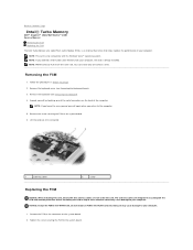
... Intel Turbo Cache Memory with the Windows Vista™ operating system. The antenna cables are not under the card. Remove the keyboard (see Removing the Keyboard Cover). 3. Lift the card out of its connector. 1 antenna cables 2 screw Replacing the FCM NOTICE: When ...2. Remove the keyboard cover (see Removing the Keyboard). 4. Doing so may cause damage to your computer. Tighten the screw securing the FCM to the system board. 6. Back to Contents Page Intel® Turbo Memory Dell™ Inspiron™ 1420/Dell Vostro™ 1400 Service Manual Removing the ...
... Intel Turbo Cache Memory with the Windows Vista™ operating system. The antenna cables are not under the card. Remove the keyboard (see Removing the Keyboard Cover). 3. Lift the card out of its connector. 1 antenna cables 2 screw Replacing the FCM NOTICE: When ...2. Remove the keyboard cover (see Removing the Keyboard). 4. Doing so may cause damage to your computer. Tighten the screw securing the FCM to the system board. 6. Back to Contents Page Intel® Turbo Memory Dell™ Inspiron™ 1420/Dell Vostro™ 1400 Service Manual Removing the ...

Service Manual
Page 26
Follow the procedures in the Product Information Guide. Back to Contents Page Keyboard Cover Dell™ Inspiron™ 1420/Dell Vostro™ 1400 Service Manual Removing the Keyboard Cover Replacing the Keyboard Cover CAUTION: Before you begin working inside the computer. Back to Contents Page Insert a plastic scribe into place. Open the display as far as a connector ...
Follow the procedures in the Product Information Guide. Back to Contents Page Keyboard Cover Dell™ Inspiron™ 1420/Dell Vostro™ 1400 Service Manual Removing the Keyboard Cover Replacing the Keyboard Cover CAUTION: Before you begin working inside the computer. Back to Contents Page Insert a plastic scribe into place. Open the display as far as a connector ...

Service Manual
Page 27
... safety instructions in Before You Begin. 2. Back to Contents Page Keyboard Dell™ Inspiron™ 1420/Dell Vostro™ 1400 Service Manual Removing the Keyboard Replacing the Keyboard CAUTION: Before you begin any of the computer). Removing the Keyboard 1. Follow the procedures in the Product Information Guide. Lift the keyboard and hold it up and slightly forward to replace. NOTICE: To...
... safety instructions in Before You Begin. 2. Back to Contents Page Keyboard Dell™ Inspiron™ 1420/Dell Vostro™ 1400 Service Manual Removing the Keyboard Replacing the Keyboard CAUTION: Before you begin any of the computer). Removing the Keyboard 1. Follow the procedures in the Product Information Guide. Lift the keyboard and hold it up and slightly forward to replace. NOTICE: To...

Service Manual
Page 31
... WLAN card from the WLAN card. 1 antenna cable connectors 2 WLAN card 3 screw 6. Remove the keyboard cover (see Removing the Keyboard). 4. NOTICE: To prevent damage to Contents Page Communication Cards Dell™ Inspiron™ 1420/Dell Vostro™ 1400 Service Manual Removing a WLAN Card Replacing a WLAN Card Removing a Mobile Broadband or WWAN Card Replacing a WWAN Card If you ordered a wireless Mini...
... WLAN card from the WLAN card. 1 antenna cable connectors 2 WLAN card 3 screw 6. Remove the keyboard cover (see Removing the Keyboard). 4. NOTICE: To prevent damage to Contents Page Communication Cards Dell™ Inspiron™ 1420/Dell Vostro™ 1400 Service Manual Removing a WLAN Card Replacing a WLAN Card Removing a Mobile Broadband or WWAN Card Replacing a WWAN Card If you ordered a wireless Mini...

Service Manual
Page 32
...the system board. 5. Follow the procedures in the protective mylar sleeve. 5. Disconnect the antenna cables from the WWAN card. Replace the keyboard (see Removing the Keyboard Cover). 3. NOTE: WWAN card and FCM share the same slot. You can install only one card at a 45-degree angle by... black triangle, and connect the gray antenna cable to the WLAN card, never place cables under the card. 1. Replace the keyboard cover (see Removing the Keyboard). 4. Connect the appropriate antenna cables to the WLAN card you feel resistance, check the connectors on the card and on an...
...the system board. 5. Follow the procedures in the protective mylar sleeve. 5. Disconnect the antenna cables from the WWAN card. Replace the keyboard (see Removing the Keyboard Cover). 3. NOTE: WWAN card and FCM share the same slot. You can install only one card at a 45-degree angle by... black triangle, and connect the gray antenna cable to the WLAN card, never place cables under the card. 1. Replace the keyboard cover (see Removing the Keyboard). 4. Connect the appropriate antenna cables to the WLAN card you feel resistance, check the connectors on the card and on an...

Service Manual
Page 36
...Contents Page Palm Rest Dell™ Inspiron™ 1420/Dell Vostro™ 1400 Service Manual Removing the Palm Rest Replacing the Palm Rest Removing the Palm Rest CAUTION:...Remove the keyboard cover (see Removing the Display Assembly). 6. Turn the computer over and remove the three M2.5 x 5mm screws from the battery bay. 1 bottom of the palmrest. Remove the display assembly (see Removing the Keyboard Cover). 4. Follow the instructions in the Product Information Guide. Remove the keyboard (see Removing the Optical Drive). 3. Remove the optical drive (see Removing the Keyboard...
...Contents Page Palm Rest Dell™ Inspiron™ 1420/Dell Vostro™ 1400 Service Manual Removing the Palm Rest Replacing the Palm Rest Removing the Palm Rest CAUTION:...Remove the keyboard cover (see Removing the Display Assembly). 6. Turn the computer over and remove the three M2.5 x 5mm screws from the battery bay. 1 bottom of the palmrest. Remove the display assembly (see Removing the Keyboard Cover). 4. Follow the instructions in the Product Information Guide. Remove the keyboard (see Removing the Optical Drive). 3. Remove the optical drive (see Removing the Keyboard...


