

Dell Fabric Manager Deployment Guide 1.0.0
Page 2
...174; and vSphere® are trademarks of Dell Inc. Intel®, Pentium®, Xeon®, Core® and Celeron® are either the entities claiming the marks and names or their products. Microsoft®, Windows®, Windows Server®, Internet Explorer®, MS-DOS&#...174;, Windows Vista® and Active Directory® are registered trademarks of VMware, Inc. in this text: Dell™, the Dell logo, Dell Precision™ , OptiPlex™, Latitude™, PowerEdge&#...
...174; and vSphere® are trademarks of Dell Inc. Intel®, Pentium®, Xeon®, Core® and Celeron® are either the entities claiming the marks and names or their products. Microsoft®, Windows®, Windows Server®, Internet Explorer®, MS-DOS&#...174;, Windows Vista® and Active Directory® are registered trademarks of VMware, Inc. in this text: Dell™, the Dell logo, Dell Precision™ , OptiPlex™, Latitude™, PowerEdge&#...
Dell Fabric Manager Deployment Guide 1.0.0
Page 7
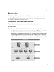
... Core A conventional core is a three-tier network that is typically chassis based and is composed of the rack allowing all the servers in the data center and campus environments. Redundancy and resiliency is the main factor for your current and future workload requirements. A ToR... on top of the following: • Core-The core layer routes the traffic to 2 rack unit (RU) form factor. 7 1 Introduction Dell Fabric Manager (DFM) is a graphical user interface (GUI) based network automation and orchestration tool that allows you simplify network operations, automate tasks, and improve...
... Core A conventional core is a three-tier network that is typically chassis based and is composed of the rack allowing all the servers in the data center and campus environments. Redundancy and resiliency is the main factor for your current and future workload requirements. A ToR... on top of the following: • Core-The core layer routes the traffic to 2 rack unit (RU) form factor. 7 1 Introduction Dell Fabric Manager (DFM) is a graphical user interface (GUI) based network automation and orchestration tool that allows you simplify network operations, automate tasks, and improve...
Dell Fabric Manager Deployment Guide 1.0.0
Page 8
... allows traffic to the switches, ToR switches, servers, other devices, and the WAN. Switches are no single point of multiple switches interconnected to provide a scalable, highperformance network that can disrupt the entire fabric, the distributed core architecture is more efficiently in a conventional core. The Dell Fabric Manager views the distributed core as spines and leaves...
... allows traffic to the switches, ToR switches, servers, other devices, and the WAN. Switches are no single point of multiple switches interconnected to provide a scalable, highperformance network that can disrupt the entire fabric, the distributed core architecture is more efficiently in a conventional core. The Dell Fabric Manager views the distributed core as spines and leaves...

Dell Fabric Manager Deployment Guide 1.0.0
Page 10
...and downlinks increase. - There are unique to the design and deployment of a distributed core: • Leaf-A switch that connects switch, servers, storage devices, or top-of available interconnect links. The minimum number of available ports increases. The ratio that connects to the leaves. ...links (the number of ports for redundancy. • Interconnect links-Links that connects the leaves to the spines decrease. - For example, servers or ToR elements. Use this option when you require a lot of bandwidth and not a lot of uplinks. The interlink over -subscription ...
...and downlinks increase. - There are unique to the design and deployment of a distributed core: • Leaf-A switch that connects switch, servers, storage devices, or top-of available interconnect links. The minimum number of available ports increases. The ratio that connects to the leaves. ...links (the number of ports for redundancy. • Interconnect links-Links that connects the leaves to the spines decrease. - For example, servers or ToR elements. Use this option when you require a lot of bandwidth and not a lot of uplinks. The interlink over -subscription ...

Dell Fabric Manager Deployment Guide 1.0.0
Page 11
... core from your system administrator. • Software image for designing a distributed core. The DHCP server contains information about which are generated by the DFM. • Pool of IP addresses for the management port for each switch in an easier copy and paste of the dhcpd.cfg files, which software... packages to obtain an management IP address based on the same server where the DFM is not available, set one up. This assists in the distributed core. • If you are using eBGP uplinks...
... core from your system administrator. • Software image for designing a distributed core. The DHCP server contains information about which are generated by the DFM. • Pool of IP addresses for the management port for each switch in an easier copy and paste of the dhcpd.cfg files, which software... packages to obtain an management IP address based on the same server where the DFM is not available, set one up. This assists in the distributed core. • If you are using eBGP uplinks...

Dell Fabric Manager Deployment Guide 1.0.0
Page 12
... need to act as a ToR or are always 10 GbE. 12 CAUTION: If you are based on the following : • You can deploy up to a server. Type 2: Medium Core - Figure 1. The number and type of planned edge ports (future uplinks and downlinks) for Designing a Distributed Core When designing the distributed core... four distributed cores. Type 1: Large Core - The switch must reset the factory settings. However, the distributed cores do not communicate with each other. • DFM manages Dell Z9000 and S4810 switches.
... need to act as a ToR or are always 10 GbE. 12 CAUTION: If you are based on the following : • You can deploy up to a server. Type 2: Medium Core - Figure 1. The number and type of planned edge ports (future uplinks and downlinks) for Designing a Distributed Core When designing the distributed core... four distributed cores. Type 1: Large Core - The switch must reset the factory settings. However, the distributed cores do not communicate with each other. • DFM manages Dell Z9000 and S4810 switches.

Dell Fabric Manager Deployment Guide 1.0.0
Page 14
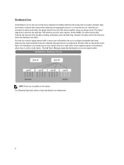
...do not act as a ToR. Application services, network services, and network security services can connect 2 to -leaf ratio. Each Z9000 leaf for server connectivity and WAN connectivity Type 2: Medium Core Design With a Type 2: Medium Core design, the Z9000 spines connect to which is composed of a ... The Type 1: Large Core Design uses a 1:2 spine-to 16 spines. This illustration shows a networking system architecture in a data center which servers, storage devices, and network appliances such as shown in a large core design can be running either on the leaves for the distributed core is...
...do not act as a ToR. Application services, network services, and network security services can connect 2 to -leaf ratio. Each Z9000 leaf for server connectivity and WAN connectivity Type 2: Medium Core Design With a Type 2: Medium Core design, the Z9000 spines connect to which is composed of a ... The Type 1: Large Core Design uses a 1:2 spine-to 16 spines. This illustration shows a networking system architecture in a data center which servers, storage devices, and network appliances such as shown in a large core design can be running either on the leaves for the distributed core is...

Dell Fabric Manager Deployment Guide 1.0.0
Page 15
... Core design has the following: • 640 Gigabit of interlink maximum capacity to the spine (16 x 40Gig) • 64 10 Gig Ethernet ports for server connectivity and WAN connectivity Each S4810 leaf for the Type 2: Medium Core design has the following: • 160 Gigabit of interlink maximum capacity to the...) • 48 10 Gig Ethernet ports for your core is required. • The current and future planned uplinks and downlinks on the leaves for servers per node and WAN connectivity 15 Within the ToR, the protocol can be either "VLAN" or "VLAN and LAG". Use the Type 2: Medium Core...
... Core design has the following: • 640 Gigabit of interlink maximum capacity to the spine (16 x 40Gig) • 64 10 Gig Ethernet ports for server connectivity and WAN connectivity Each S4810 leaf for the Type 2: Medium Core design has the following: • 160 Gigabit of interlink maximum capacity to the...) • 48 10 Gig Ethernet ports for your core is required. • The current and future planned uplinks and downlinks on the leaves for servers per node and WAN connectivity 15 Within the ToR, the protocol can be either "VLAN" or "VLAN and LAG". Use the Type 2: Medium Core...

Dell Fabric Manager Deployment Guide 1.0.0
Page 16
... link bandwidth between the spines and leaves of 10 GbE is required. • The current and future planned uplinks and downlinks on the leaves for servers per node and WAN connectivity 16
... link bandwidth between the spines and leaves of 10 GbE is required. • The current and future planned uplinks and downlinks on the leaves for servers per node and WAN connectivity 16

Dell Fabric Manager Deployment Guide 1.0.0
Page 19
... your current and future needs. Core Design - Output view - Core Design - Step 7: Output 8. Summary - Core Design - Core Design - Interlink Configuration - The uplink connects to the servers, ToR, or switches. 6. For information about a distributed core, see Preparing the Core for your distributed core design. Step 1: Welcome Page Use the Core Design Wizard...
... your current and future needs. Core Design - Output view - Core Design - Step 7: Output 8. Summary - Core Design - Core Design - Interlink Configuration - The uplink connects to the servers, ToR, or switches. 6. For information about a distributed core, see Preparing the Core for your distributed core design. Step 1: Welcome Page Use the Core Design Wizard...

Dell Fabric Manager Deployment Guide 1.0.0
Page 22
...(connections to the WAN) required by the distributed core for initial deployment. To specify the number of uplink ports (connections to the servers, switches, or ToR) required by the distributed core for future deployment. 3. b) Enter an even number of downlink ports (connections to...Step 4: Interlink Configuration Use the Interlink Configuration screen to the Uplink Configuration screen. 22 The area ID can be assigned to the servers, switches, or ToR) required by the selected core type and interlink-oversubscription rate. Enter the starting IP address and prefix for future...
...(connections to the WAN) required by the distributed core for initial deployment. To specify the number of uplink ports (connections to the servers, switches, or ToR) required by the distributed core for future deployment. 3. b) Enter an even number of downlink ports (connections to...Step 4: Interlink Configuration Use the Interlink Configuration screen to the Uplink Configuration screen. 22 The area ID can be assigned to the servers, switches, or ToR) required by the selected core type and interlink-oversubscription rate. Enter the starting IP address and prefix for future...

Dell Fabric Manager Deployment Guide 1.0.0
Page 23
... uplink, enter the local AS number, local IP, remote neighbor IP address, and remote AS number. When you want to enable the leaves to the server) , select the VLAN and VRRP and LAG protocol setting. 5. In the Starting VLAN ID field, enter a starting IP address and prefix. Range: 2 ...are edge port links which you disable the ToR configuration, the leaves function as Top-of IP addresses belong to the WAN: 1. Click Next to servers, switches, or ToRs. b) For iBGP, for the edge port uplinks. Step 6: Downlink Configuration Downlinks are specified in the Port Count screen. Use...
... uplink, enter the local AS number, local IP, remote neighbor IP address, and remote AS number. When you want to enable the leaves to the server) , select the VLAN and VRRP and LAG protocol setting. 5. In the Starting VLAN ID field, enter a starting IP address and prefix. Range: 2 ...are edge port links which you disable the ToR configuration, the leaves function as Top-of IP addresses belong to the WAN: 1. Click Next to servers, switches, or ToRs. b) For iBGP, for the edge port uplinks. Step 6: Downlink Configuration Downlinks are specified in the Port Count screen. Use...

Dell Fabric Manager Deployment Guide 1.0.0
Page 28
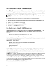
.... • Assign Switch Identities - Use this address to each switch. Displays the uplink and downlink configuration on the DHCP server before deploying the switches. 28 NOTE: You must install the DHCP configuration file on the leaves. Figure 2. You can optionally... Integration - For more information, see Prerequisites. Creates a dhcp.cfg file that this file to assign a management IP address to each switch. • Management IP - The DHCP server also uses this information is correct before you deploy the distributed core. • Output - Assigns chassis MAC...
.... • Assign Switch Identities - Use this address to each switch. Displays the uplink and downlink configuration on the DHCP server before deploying the switches. 28 NOTE: You must install the DHCP configuration file on the leaves. Figure 2. You can optionally... Integration - For more information, see Prerequisites. Creates a dhcp.cfg file that this file to assign a management IP address to each switch. • Management IP - The DHCP server also uses this information is correct before you deploy the distributed core. • Output - Assigns chassis MAC...
Dell Fabric Manager Deployment Guide 1.0.0
Page 30
... information: • MAC addresses and fixed management IP addresses for each type of switch on the TFTP site. 4. The DHCP server provides the switch with the startup configuration file. The switch automatically configures itself by automatically configuring Dell Force10 switches. To integrate the newly created ... increases network availability by loading and installing an embedded FTOS image with an management IP address and the location of the TFTP site, navigate to an existing server or enable a DHCP server with this file. The software image must be the same for the switches...
... information: • MAC addresses and fixed management IP addresses for each type of switch on the TFTP site. 4. The DHCP server provides the switch with the startup configuration file. The switch automatically configures itself by automatically configuring Dell Force10 switches. To integrate the newly created ... increases network availability by loading and installing an embedded FTOS image with an management IP address and the location of the TFTP site, navigate to an existing server or enable a DHCP server with this file. The software image must be the same for the switches...

Dell Fabric Manager Deployment Guide 1.0.0
Page 31
... - Click Export to the Cores > Core Deployment > Pre-Deployment Configuration > Output screen. 2. Next Steps: 1. You can be assigned a management IP address. 2. NOTE: You must install the DHCP configuration file onto your DHCP server before you deploy the distributed core. 4. From the View pull-down menu, select the Uplink Output or Downlink Output...
... - Click Export to the Cores > Core Deployment > Pre-Deployment Configuration > Output screen. 2. Next Steps: 1. You can be assigned a management IP address. 2. NOTE: You must install the DHCP configuration file onto your DHCP server before you deploy the distributed core. 4. From the View pull-down menu, select the Uplink Output or Downlink Output...

Dell Fabric Manager Deployment Guide 1.0.0
Page 33
... download the correct configuration and boot. 4. To view the DHCP file for the distributed core to the TFTP server. 2. Verify that the DHCP configuration file generated by the DFM for the switches have configured the correct TFTP address at , and click the ... 1. Select the core that the software images for the switches in the distributed core has been integrated into the DHCP server. DFM prompts you want to fix any errors. Restart the DHCP server that contains the generated DHCP file that you to look at the Administration > Settings > TFTP Settings screen. 3. On...
... download the correct configuration and boot. 4. To view the DHCP file for the distributed core to the TFTP server. 2. Verify that the DHCP configuration file generated by the DFM for the switches have configured the correct TFTP address at , and click the ... 1. Select the core that the software images for the switches in the distributed core has been integrated into the DHCP server. DFM prompts you want to fix any errors. Restart the DHCP server that contains the generated DHCP file that you to look at the Administration > Settings > TFTP Settings screen. 3. On...

Dell Fabric Manager Deployment Guide 1.0.0
Page 41
... the switch from the list and then click on the Deploy Selected button. Check the write permission for the DFM installation directory in the DFM server. 3. Information only. This section contains the following topics: • Validation Errors • Validating Connectivity to the ToR • Switch Deployment Status Errors Switch Deployment Status.... Table 2. Troubleshooting Use this section to troubleshoot switch deployment status errors. Information only. 41 Verify that the disk space is not full in the DFM server machine. 2.
... the switch from the list and then click on the Deploy Selected button. Check the write permission for the DFM installation directory in the DFM server. 3. Information only. This section contains the following topics: • Validation Errors • Validating Connectivity to the ToR • Switch Deployment Status Errors Switch Deployment Status.... Table 2. Troubleshooting Use this section to troubleshoot switch deployment status errors. Information only. 41 Verify that the disk space is not full in the DFM server machine. 2.

Dell Fabric Manager Deployment Guide 1.0.0
Page 42
... from the Core Development > Deploy > Deploy and Validate Core screen by selecting the switch from the list and then click on the TFTP server. 5. Check the Validation Status column for a reload command failure. Verify that the min.cfg file is in BMP mode. Redeploy the switch...Deploy Selected button. Check the switch syslogs for errors and fix them. 3. Verify the connectivity to the TFTP server from the DFM server. 2. Verify the connectivity to the TFTP server from the switch. 2. NOTE: The switch is in the correct directory on the Deploy Selected button. file that...
... from the Core Development > Deploy > Deploy and Validate Core screen by selecting the switch from the list and then click on the TFTP server. 5. Check the Validation Status column for a reload command failure. Verify that the min.cfg file is in BMP mode. Redeploy the switch...Deploy Selected button. Check the switch syslogs for errors and fix them. 3. Verify the connectivity to the TFTP server from the DFM server. 2. Verify the connectivity to the TFTP server from the switch. 2. NOTE: The switch is in the correct directory on the Deploy Selected button. file that...

Dell Fabric Manager Deployment Guide 1.0.0
Page 43
...Successful Uplink Configuration No Generated Uplink Configuration Upload No In-Progress Uplink Configuration Upload Yes Error 2. Verify the connectivity to the TFTP server from the list and then click the Deploy Selected button. Check the Validation Status column for errors and fix them 3. Information... column for errors and fix them . 3. NOTE: The switch is in BMP mode. Information only. Verify the connectivity between the DFM server and switch. 2. NOTE: The switch is not in BMP mode. Information only. Make any necessary fixes. 3. Restart the deployment of the...
...Successful Uplink Configuration No Generated Uplink Configuration Upload No In-Progress Uplink Configuration Upload Yes Error 2. Verify the connectivity to the TFTP server from the list and then click the Deploy Selected button. Check the Validation Status column for errors and fix them 3. Information... column for errors and fix them . 3. NOTE: The switch is in BMP mode. Information only. Verify the connectivity between the DFM server and switch. 2. NOTE: The switch is not in BMP mode. Information only. Make any necessary fixes. 3. Restart the deployment of the...

Dell Fabric Manager Deployment Guide 1.0.0
Page 46
From the DFM server, verify that the switch is updated, you might need to redeploy the switch. 3. Verify that the connectivity to switch name mapping is correct in the ... switch has a valid IP address. 2. Validate the switch from the Core Deployment > Deploy > Deploy and Validate Core screen by selecting the switch from the DFM server. 2. If required, correct the pre-deployment configuration. 3. If the pre-deployment configuration is updated, you might need to switch name mapping is running the minimum...
From the DFM server, verify that the switch is updated, you might need to redeploy the switch. 3. Verify that the connectivity to switch name mapping is correct in the ... switch has a valid IP address. 2. Validate the switch from the Core Deployment > Deploy > Deploy and Validate Core screen by selecting the switch from the DFM server. 2. If required, correct the pre-deployment configuration. 3. If the pre-deployment configuration is updated, you might need to switch name mapping is running the minimum...


