
Owners Manual
Page 20
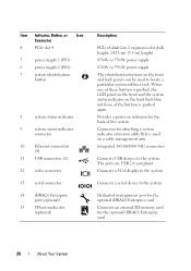
... video connector 13 serial connector 14 iDRAC6 Enterprise port (optional) 15 VFlash media slot (optional) Description PCIe x8-link Gen 2 expansion slot (fullheight, 24.13-cm [9.5-in] length) 870-W or 570-W power supply 870-W or 570-W power supply The identification buttons on the front and back panels can be used on a cable management arm Integrated 10/100/1000 NIC connectors Connects USB devices to the system Dedicated management port for the optional iDRAC6 Enterprise card Connects an external SD memory card...
... video connector 13 serial connector 14 iDRAC6 Enterprise port (optional) 15 VFlash media slot (optional) Description PCIe x8-link Gen 2 expansion slot (fullheight, 24.13-cm [9.5-in] length) 870-W or 570-W power supply 870-W or 570-W power supply The identification buttons on the front and back panels can be used on a cable management arm Integrated 10/100/1000 NIC connectors Connects USB devices to the system Dedicated management port for the optional iDRAC6 Enterprise card Connects an external SD memory card...
Owners Manual
Page 41
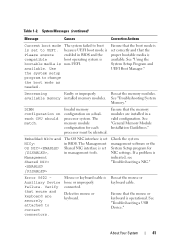
... Device Failure. See "Using the System Setup Program and UEFI Boot Manager." Decreasing Faulty or improperly Reseat the memory modules. DIMM configuration on a dualprocessor system. Table 1-2. Ensure that the proper bootable media is set to correct connectors. Mouse or keyboard cable is indicated, see "Troubleshooting a NIC." See "Troubleshooting a USB Device." because UEFI boot mode is Please ensure enabled in BIOS and the compatible boot operating system is bootable media is set in management tools. Defective mouse or keyboard. Invalid memory configuration...
... Device Failure. See "Using the System Setup Program and UEFI Boot Manager." Decreasing Faulty or improperly Reseat the memory modules. DIMM configuration on a dualprocessor system. Table 1-2. Ensure that the proper bootable media is set to correct connectors. Mouse or keyboard cable is indicated, see "Troubleshooting a NIC." See "Troubleshooting a USB Device." because UEFI boot mode is Please ensure enabled in BIOS and the compatible boot operating system is bootable media is set in management tools. Defective mouse or keyboard. Invalid memory configuration...

Owners Manual
Page 55
... startup. DOS and 32-bit operating systems do not support UEFI and can : • Change the NVRAM settings after you add or remove hardware • View the system hardware configuration • Enable or disable integrated devices • Set performance and power management thresholds • Manage system security Choosing the System Boot Mode The System Setup program also enables you must be UEFI-compatible (for more information on Unified Extensible Firmware Interface (UEFI) specifications...
... startup. DOS and 32-bit operating systems do not support UEFI and can : • Change the NVRAM settings after you add or remove hardware • View the system hardware configuration • Enable or disable integrated devices • Set performance and power management thresholds • Manage system security Choosing the System Boot Mode The System Setup program also enables you must be UEFI-compatible (for more information on Unified Extensible Firmware Interface (UEFI) specifications...

Owners Manual
Page 61
... boot manager utility by rebooting the system and pressing when prompted to SATA port B. Auto automatically chooses an emulation type. Option Port B (Off default) Description Auto enables BIOS support for the device attached to do so. Determines the order in which the BIOS will automatically emulate a hard drive. A device installed in the internal SD card slot. Off disables BIOS support for a USB flash drive. Boot Settings Screen Option Boot Mode (BIOS default) Boot Sequence Hard-Disk Drive Sequence USB Flash Drive Emulation Type (Auto default) Description CAUTION: Switching the boot...
... boot manager utility by rebooting the system and pressing when prompted to SATA port B. Auto automatically chooses an emulation type. Option Port B (Off default) Description Auto enables BIOS support for the device attached to do so. Determines the order in which the BIOS will automatically emulate a hard drive. A device installed in the internal SD card slot. Off disables BIOS support for a USB flash drive. Boot Settings Screen Option Boot Mode (BIOS default) Boot Sequence Hard-Disk Drive Sequence USB Flash Drive Emulation Type (Auto default) Description CAUTION: Switching the boot...

Owners Manual
Page 72
... changes. As you type, placeholders appear in the system password menu. After the third unsuccessful attempt, the system displays an error message that the Password Status is Unlocked. 4 Type the new system password in your password. You can enter the System Setup program and press twice in the field. 72 Using the System Setup Program and UEFI Boot Manager To assign a setup password, highlight the Setup Password option and press the or key...
... changes. As you type, placeholders appear in the system password menu. After the third unsuccessful attempt, the system displays an error message that the Password Status is Unlocked. 4 Type the new system password in your password. You can enter the System Setup program and press twice in the field. 72 Using the System Setup Program and UEFI Boot Manager To assign a setup password, highlight the Setup Password option and press the or key...

Owners Manual
Page 73
... key. A change an existing system password. The following options are exceptions: If System Password is not Enabled and is not locked through the dedicated iDRAC6 Enterprise card port or the embedded NICs. • Enable or disable IPMI over LAN. Press twice to access the setup password window. Using the System Setup Program and UEFI Boot Manager 73 The setting changes to Not Enabled. 3 If you can use the Password Status option in conjunction with the Setup Password option...
... key. A change an existing system password. The following options are exceptions: If System Password is not Enabled and is not locked through the dedicated iDRAC6 Enterprise card port or the embedded NICs. • Enable or disable IPMI over LAN. Press twice to access the setup password window. Using the System Setup Program and UEFI Boot Manager 73 The setting changes to Not Enabled. 3 If you can use the Password Status option in conjunction with the Setup Password option...

Owners Manual
Page 120
... 6 Non-Dell storage cards 1,2,3,4 41 N2 1 Maximum of 2 of two PERC or SAS controller expansion cards to ensure that came with the highest priority should only perform troubleshooting and simple repairs as directed by the online or telephone service and support team. You should be installed first using the slot priority indicated. Read and follow the safety instructions that the maximum power does...
... 6 Non-Dell storage cards 1,2,3,4 41 N2 1 Maximum of 2 of two PERC or SAS controller expansion cards to ensure that came with the highest priority should only perform troubleshooting and simple repairs as directed by the online or telephone service and support team. You should be installed first using the slot priority indicated. Read and follow the safety instructions that the maximum power does...
Owners Manual
Page 154
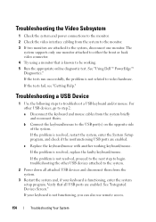
... back video connector. 4 Try using a monitor that all attached USB devices and disconnect them from the system briefly and reconnect them. If the tests fail, see "Getting Help." b Connect the keyboard/mouse to troubleshoot a USB keyboard and/or mouse. The system supports only one monitor. See "Integrated Devices Screen." If the problem is resolved, restart the system, enter the System Setup program, and check if the nonfunctioning USB ports are enabled. c Replace the keyboard/mouse with another working . 5 Run...
... back video connector. 4 Try using a monitor that all attached USB devices and disconnect them from the system briefly and reconnect them. If the tests fail, see "Getting Help." b Connect the keyboard/mouse to troubleshoot a USB keyboard and/or mouse. The system supports only one monitor. See "Integrated Devices Screen." If the problem is resolved, restart the system, enter the System Setup program, and check if the nonfunctioning USB ports are enabled. c Replace the keyboard/mouse with another working . 5 Run...

Owners Manual
Page 156
... or telephone service and support team. See "Installing System Components." • Cooling shroud • Hard drives • SD cards • USB memory key • NIC hardware key • Internal SD Module • Expansion cards and both expansion-card risers • Integrated storage controller • iDRAC6 Enterprise card 156 Troubleshooting Your System See the NIC's documentation. 5 Enter the System Setup program and confirm that all network cables are of the proper type and...
... or telephone service and support team. See "Installing System Components." • Cooling shroud • Hard drives • SD cards • USB memory key • NIC hardware key • Internal SD Module • Expansion cards and both expansion-card risers • Integrated storage controller • iDRAC6 Enterprise card 156 Troubleshooting Your System See the NIC's documentation. 5 Enter the System Setup program and confirm that all network cables are of the proper type and...

Owners Manual
Page 161
... startup without video output. Go to step 14 if an error message appears indicating a fault with all applicable guidelines. 1 If the system is operational, run the appropriate online diagnostic test. Make any changes to its electrical outlet, and turn off the system and attached peripherals, and disconnect the system from the power source. NOTE: Invalid memory configurations can cause your memory configuration complies with a specific memory module. 4 Enter...
... startup without video output. Go to step 14 if an error message appears indicating a fault with all applicable guidelines. 1 If the system is operational, run the appropriate online diagnostic test. Make any changes to its electrical outlet, and turn off the system and attached peripherals, and disconnect the system from the power source. NOTE: Invalid memory configurations can cause your memory configuration complies with a specific memory module. 4 Enter...

Owners Manual
Page 162
... boots, observe any error message that is not authorized by a certified service technician. See "Integrated Devices Screen." 162 Troubleshooting Your System 13 Enter the System Setup program and check the system memory setting. See "Memory Settings Screen." Troubleshooting an Internal SD Card CAUTION: Many repairs may only be done by Dell is not resolved, proceed with a module of the system. 23 If the memory problem is enabled. You should only perform troubleshooting...
... boots, observe any error message that is not authorized by a certified service technician. See "Integrated Devices Screen." 162 Troubleshooting Your System 13 Enter the System Setup program and check the system memory setting. See "Memory Settings Screen." Troubleshooting an Internal SD Card CAUTION: Many repairs may only be done by Dell is not resolved, proceed with a module of the system. 23 If the memory problem is enabled. You should only perform troubleshooting...

Owners Manual
Page 164
... only perform troubleshooting and simple repairs as directed by Dell is enabled. Read and follow the safety instructions that you know works properly. 9 Close the system. 6 Turn on the system and attached peripherals and check if the USB key is functioning. See "Removing the Front Bezel." 2 Try using a different DVD. 3 Ensure that the device drivers for the optical drive are installed and are configured correctly 4 Enter the System Setup program...
... only perform troubleshooting and simple repairs as directed by Dell is enabled. Read and follow the safety instructions that you know works properly. 9 Close the system. 6 Turn on the system and attached peripherals and check if the USB key is functioning. See "Removing the Front Bezel." 2 Try using a different DVD. 3 Ensure that the device drivers for the optical drive are installed and are configured correctly 4 Enter the System Setup program...

Owners Manual
Page 166
... system board SATA connector. a Restart the system and enter the host adapter configuration utility program by your warranty. See "Closing the System." 11 Reconnect the system to the drive and the system board. 10 Close the system. See the documentation supplied with the product. c Ensure that a power cable is properly connected to the electrical outlet, and turn on the hard drive. 1 Run the appropriate online diagnostics test. See "Using Dell™...
... system board SATA connector. a Restart the system and enter the host adapter configuration utility program by your warranty. See "Closing the System." 11 Reconnect the system to the drive and the system board. 10 Close the system. See the documentation supplied with the product. c Ensure that a power cable is properly connected to the electrical outlet, and turn on the hard drive. 1 Run the appropriate online diagnostics test. See "Using Dell™...
Owners Manual
Page 179
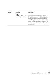
If the configuration settings become corrupted to the point where the system will not boot, install the jumper and boot the system. Jumpers and Connectors 179 Jumper Setting Description Pins 1 and 3 The configuration settings are cleared at the next system boot. Remove the jumper before restoring the configuration information.
If the configuration settings become corrupted to the point where the system will not boot, install the jumper and boot the system. Jumpers and Connectors 179 Jumper Setting Description Pins 1 and 3 The configuration settings are cleared at the next system boot. Remove the jumper before restoring the configuration information.
Owners Manual
Page 197
... I /O devices. serial port - Used to describe a system that has two or more disks in effect until you call Dell for operation. Allows hard drives to report errors and failures to I /O bus interface. Secure digital flash memory card. Disk striping writes data across three or more processors connected via a high-bandwidth link and managed by setting features such as the processor(s), RAM, controllers for peripherals, and various ROM chips. SCSI - SD card - Symmetric multiprocessing. Simple Network Management...
... I /O devices. serial port - Used to describe a system that has two or more disks in effect until you call Dell for operation. Allows hard drives to report errors and failures to I /O bus interface. Secure digital flash memory card. Disk striping writes data across three or more processors connected via a high-bandwidth link and managed by setting features such as the processor(s), RAM, controllers for peripherals, and various ROM chips. SCSI - SD card - Symmetric multiprocessing. Simple Network Management...
Owners Manual
Page 198
... can be connected and disconnected while the system is usually rounded to the network controller. UPS - A battery-powered unit that automatically supplies power to your system in the cable. Video resolution (800 x 600, for the devices. TCP/IP offload engine. utility - TCP/IP - Unified Extensible Firmware Interface. Volt(s). An unregistered (unbuffered) DDR3 memory module. Uninterruptible power supply. video adapter - UEFI - USB devices can display (with the monitor) your system's RAM. termination - Terabyte...
... can be connected and disconnected while the system is usually rounded to the network controller. UPS - A battery-powered unit that automatically supplies power to your system in the cable. Video resolution (800 x 600, for the devices. TCP/IP offload engine. utility - TCP/IP - Unified Extensible Firmware Interface. Volt(s). An unregistered (unbuffered) DDR3 memory module. Uninterruptible power supply. video adapter - UEFI - USB devices can display (with the monitor) your system's RAM. termination - Terabyte...
Owners Manual
Page 201
... battery (system) replacing, 141 troubleshooting, 158 BIOS boot mode, 55 blank hard drive, 81 power supply, 88 boot mode, 55 C cable retention bracket installing, 119 removing, 118 cable routing, 118 cabling cable routing, 118 optical drive, 103 storage controller (2.5-in HDD chassis), 114 storage controller (four 3.5-in HDD chassis), 115 storage controller (six 3.5-in HDD chassis), 116 connectors expansion-card riser 1, 185 expansion-card riser 2, 186-187 NIC, 20 SAS backplane board, 182 serial, 20 system board, 180 USB, 12 video, 12 contacting Dell, 189 control panel...
... battery (system) replacing, 141 troubleshooting, 158 BIOS boot mode, 55 blank hard drive, 81 power supply, 88 boot mode, 55 C cable retention bracket installing, 119 removing, 118 cable routing, 118 cabling cable routing, 118 optical drive, 103 storage controller (2.5-in HDD chassis), 114 storage controller (four 3.5-in HDD chassis), 115 storage controller (six 3.5-in HDD chassis), 116 connectors expansion-card riser 1, 185 expansion-card riser 2, 186-187 NIC, 20 SAS backplane board, 182 serial, 20 system board, 180 USB, 12 video, 12 contacting Dell, 189 control panel...

Owners Manual
Page 206
..., 115 cabling for six 3.5-in HDD chassis, 116 installing, 112 removing, 112 troubleshooting, 167 support contacting Dell, 189 system board connectors, 180 installing, 150 jumpers, 177 removing, 148 system cooling troubleshooting, 159 system features accessing, 11 system messages, 37 system password, 70 system setup program boot settings, 61 embedded server management options, 64 integrated devices options, 62 keystroke to enter, 56 main screen, 57 memory settings, 59 PCI IRQ assignments, 63 power management options, 65 processor settings, 60 SATA settings, 60 serial communications options, 63...
..., 115 cabling for six 3.5-in HDD chassis, 116 installing, 112 removing, 112 troubleshooting, 167 support contacting Dell, 189 system board connectors, 180 installing, 150 jumpers, 177 removing, 148 system cooling troubleshooting, 159 system features accessing, 11 system messages, 37 system password, 70 system setup program boot settings, 61 embedded server management options, 64 integrated devices options, 62 keystroke to enter, 56 main screen, 57 memory settings, 59 PCI IRQ assignments, 63 power management options, 65 processor settings, 60 SATA settings, 60 serial communications options, 63...
Owners Manual
Page 207
..., 157 external connections, 153 hard drive, 166 internal USB memory key, 163 keyboard, 154 memory, 160 NIC, 155 optical drive, 164 PCIe expansion cards, 168 power supplies, 158 processor(s), 170 SD card, 162 storage controller, 167 system battery, 158 system cooling, 159 system startup failure, 153 tape backup unit, 165 video, 154 wet system, 156 U UEFI Boot Manager entering, 68 main screen, 69 System Utilities screen, 69 UEFI Boot Settings screen, 69 UEFI boot mode, 55 upgrades processor, 137 USB back-panel connectors, 20 front-panel connectors, 12 USB cable internal installing, 93 removing...
..., 157 external connections, 153 hard drive, 166 internal USB memory key, 163 keyboard, 154 memory, 160 NIC, 155 optical drive, 164 PCIe expansion cards, 168 power supplies, 158 processor(s), 170 SD card, 162 storage controller, 167 system battery, 158 system cooling, 159 system startup failure, 153 tape backup unit, 165 video, 154 wet system, 156 U UEFI Boot Manager entering, 68 main screen, 69 System Utilities screen, 69 UEFI Boot Settings screen, 69 UEFI boot mode, 55 upgrades processor, 137 USB back-panel connectors, 20 front-panel connectors, 12 USB cable internal installing, 93 removing...

Deployment Guide
Page 6
... changes needed to add the network adapter driver. When booting to the Deployment Agent, ADS gives the following error: Windows could not start due to build a bootable RAMDISK image. To assist, Dell developed the Dell USB Key F6 Driver Utility. You can be downloaded from a USB key by looking in 5 seconds. Dell recommends that starting with ADS when two Intel™ Xeon™ processors are installing, the mass storage drivers may cause a problem. Microsoft Automated Deployment Service (ADS) Dell has observed a problem...
... changes needed to add the network adapter driver. When booting to the Deployment Agent, ADS gives the following error: Windows could not start due to build a bootable RAMDISK image. To assist, Dell developed the Dell USB Key F6 Driver Utility. You can be downloaded from a USB key by looking in 5 seconds. Dell recommends that starting with ADS when two Intel™ Xeon™ processors are installing, the mass storage drivers may cause a problem. Microsoft Automated Deployment Service (ADS) Dell has observed a problem...


