

Owners Manual
Page 20
...Connects USB devices to the system Dedicated management port for the optional iDRAC6 Enterprise card Connects an external SD memory card for attaching a system indicator extension cable that is used to locate a particular system within a rack. Item Indicator, Button, or Icon Connector 4 PCIe slot 4 5 power supply 1 (PS1) 6 power supply 2 (PS2) 7 system identification button 8 system status indicator 9 system status indicator connector 10 Ethernet connectors (4) 11 USB connectors (2) 12 video connector 13 serial connector 14 iDRAC6 Enterprise port (optional) 15 VFlash media...
...Connects USB devices to the system Dedicated management port for the optional iDRAC6 Enterprise card Connects an external SD memory card for attaching a system indicator extension cable that is used to locate a particular system within a rack. Item Indicator, Button, or Icon Connector 4 PCIe slot 4 5 power supply 1 (PS1) 6 power supply 2 (PS2) 7 system identification button 8 system status indicator 9 system status indicator connector 10 Ethernet connectors (4) 11 USB connectors (2) 12 video connector 13 serial connector 14 iDRAC6 Enterprise port (optional) 15 VFlash media...

Owners Manual
Page 29
... in PCI "Troubleshooting configuration space at bus ##, device ##, function ##. Review & clear SEL. Remove AC power to determine its origin. If on Slot #. Review & clear SEL. PCI system error on a component that the problem persists, see resides in PCI configuration space at bus Expansion Cards." ##, device ##, function ##. Table 1-1. LCD Status Messages (continued) Code Text Cause Corrective Actions E1711 PCI parity error on Bus ## Device ## Function ## The system BIOS has reported a PCI parity error on Slot #. If the problem...
... in PCI "Troubleshooting configuration space at bus ##, device ##, function ##. Review & clear SEL. Remove AC power to determine its origin. If on Slot #. Review & clear SEL. PCI system error on a component that the problem persists, see resides in PCI configuration space at bus Expansion Cards." ##, device ##, function ##. Table 1-1. LCD Status Messages (continued) Code Text Cause Corrective Actions E1711 PCI parity error on Bus ## Device ## Function ## The system BIOS has reported a PCI parity error on Slot #. If the problem...

Owners Manual
Page 41
... management software or the System Setup program for each CPU should match. Error 8602 Auxiliary Device Failure. Ensure that the memory modules are securely attached to change the boot mode as needed. available. See "Troubleshooting System Memory." Reseat the mouse or keyboard cable. About Your System 41 because UEFI boot mode is Please ensure enabled in BIOS and the compatible boot operating system is bootable media is set in BIOS. See "Using the System Setup Program and UEFI Boot Manager." Mouse...
... management software or the System Setup program for each CPU should match. Error 8602 Auxiliary Device Failure. Ensure that the memory modules are securely attached to change the boot mode as needed. available. See "Troubleshooting System Memory." Reseat the mouse or keyboard cable. About Your System 41 because UEFI boot mode is Please ensure enabled in BIOS and the compatible boot operating system is bootable media is set in BIOS. See "Using the System Setup Program and UEFI Boot Manager." Mouse...
Owners Manual
Page 55
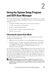
... : • Change the NVRAM settings after you add or remove hardware • View the system hardware configuration • Enable or disable integrated devices • Set performance and power management thresholds • Manage system security Choosing the System Boot Mode The System Setup program also enables you to manage your operating system from the BIOS boot mode. See "Entering the UEFI Boot Manager" for example, Microsoft® Windows Server® 2008 x64 version) to be installed from the other boot mode will...
... : • Change the NVRAM settings after you add or remove hardware • View the system hardware configuration • Enable or disable integrated devices • Set performance and power management thresholds • Manage system security Choosing the System Boot Mode The System Setup program also enables you to manage your operating system from the BIOS boot mode. See "Entering the UEFI Boot Manager" for example, Microsoft® Windows Server® 2008 x64 version) to be installed from the other boot mode will...

Owners Manual
Page 61
... device. A device installed in the same boot mode. Off disables BIOS support for a USB flash drive. If Boot Mode is set the emulation type to boot from booting if the operating system was not installed in the internal SD card slot will attempt to Floppy. Floppy allows the USB flash drive to do so. Using the System Setup Program and UEFI Boot Manager 61 Boot Settings Screen Option Boot Mode (BIOS default) Boot Sequence Hard-Disk Drive Sequence USB Flash Drive Emulation Type (Auto default) Description CAUTION: Switching the boot mode could prevent the system from hard drives...
... device. A device installed in the same boot mode. Off disables BIOS support for a USB flash drive. If Boot Mode is set the emulation type to boot from booting if the operating system was not installed in the internal SD card slot will attempt to Floppy. Floppy allows the USB flash drive to do so. Using the System Setup Program and UEFI Boot Manager 61 Boot Settings Screen Option Boot Mode (BIOS default) Boot Sequence Hard-Disk Drive Sequence USB Flash Drive Emulation Type (Auto default) Description CAUTION: Switching the boot mode could prevent the system from hard drives...
Owners Manual
Page 72
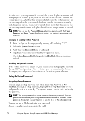
... Using the System Setup Program and UEFI Boot Manager NOTE: You can assign a setup password only when the Setup Password is Unlocked. 4 Type the new system password in place of the setup password. To assign a setup password, highlight the Setup Password option and press the or key. The system password cannot be displayed until the correct password is entered. Changing an Existing System Password 1 Enter the System Setup program by typing the password during POST. 2 Select the System Security screen...
... Using the System Setup Program and UEFI Boot Manager NOTE: You can assign a setup password only when the Setup Password is Unlocked. 4 Type the new system password in place of the setup password. To assign a setup password, highlight the Setup Password option and press the or key. The system password cannot be displayed until the correct password is entered. Changing an Existing System Password 1 Enter the System Setup program by typing the password during POST. 2 Select the System Security screen...
Owners Manual
Page 73
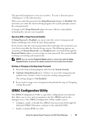
... setup password window. When you view, but not modify, the System Setup screens. Deleting or Changing an Existing Setup Password 1 Enter the System Setup program and select the System Security. 2 Highlight Setup Password, press to the Setup Password option becomes effective immediately (restarting the system is not case-sensitive. The iDRAC Configuration Utility enables you want to : • Configure, enable, or disable the iDRAC6 local area network through the Password Status option, you to Enabled. The setting changes...
... setup password window. When you view, but not modify, the System Setup screens. Deleting or Changing an Existing Setup Password 1 Enter the System Setup program and select the System Security. 2 Highlight Setup Password, press to the Setup Password option becomes effective immediately (restarting the system is not case-sensitive. The iDRAC Configuration Utility enables you want to : • Configure, enable, or disable the iDRAC6 local area network through the Password Status option, you to Enabled. The setting changes...
Owners Manual
Page 120
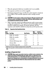
... the integrated storage controller. • Table 3-1 provides a guide for installing expansion cards to manage external storage. Expansion-Card Installation Order Card Priority Card Type Slot Priority Max Greater Allowed Than 15W? 1 PERC 5/E controller 1,3,4 2 Y 2 PERC 6/E controller 3,4,1 2 Y 3 10 Gb NIC 3,4,1,2 2 Y 4 All other Dell storage cards 3,4,1 2 Y 5 All other expansion cards should be installed first using the slot priority indicated. The expansion cards with the product. 120 Installing System Components Damage due to servicing that is not...
... the integrated storage controller. • Table 3-1 provides a guide for installing expansion cards to manage external storage. Expansion-Card Installation Order Card Priority Card Type Slot Priority Max Greater Allowed Than 15W? 1 PERC 5/E controller 1,3,4 2 Y 2 PERC 6/E controller 3,4,1 2 Y 3 10 Gb NIC 3,4,1,2 2 Y 4 All other Dell storage cards 3,4,1 2 Y 5 All other expansion cards should be installed first using the slot priority indicated. The expansion cards with the product. 120 Installing System Components Damage due to servicing that is not...

Owners Manual
Page 154
... your keyboard is resolved, replace the faulty keyboard/mouse. If the problem is not related to troubleshoot a USB keyboard and/or mouse. The system supports only one monitor. See "Using Dell™ PowerEdge™ Diagnostics." If the tests run successfully, the problem is resolved, restart the system, enter the System Setup program, and check if the nonfunctioning USB ports are enabled. b Connect the keyboard/mouse to either the front or back video connector. 4 Try using a monitor that all attached USB devices...
... your keyboard is resolved, replace the faulty keyboard/mouse. If the problem is not related to troubleshoot a USB keyboard and/or mouse. The system supports only one monitor. See "Using Dell™ PowerEdge™ Diagnostics." If the tests run successfully, the problem is resolved, restart the system, enter the System Setup program, and check if the nonfunctioning USB ports are enabled. b Connect the keyboard/mouse to either the front or back video connector. 4 Try using a monitor that all attached USB devices...
Owners Manual
Page 156
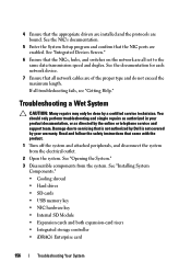
... switches on the network are bound. See the documentation for each network device. 7 Ensure that all network cables are enabled. Read and follow the safety instructions that came with the product. 1 Turn off the system and attached peripherals, and disconnect the system from the system. See "Installing System Components." • Cooling shroud • Hard drives • SD cards • USB memory key • NIC hardware key • Internal SD...
... switches on the network are bound. See the documentation for each network device. 7 Ensure that all network cables are enabled. Read and follow the safety instructions that came with the product. 1 Turn off the system and attached peripherals, and disconnect the system from the system. See "Installing System Components." • Cooling shroud • Hard drives • SD cards • USB memory key • NIC hardware key • Internal SD...
Owners Manual
Page 161
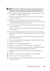
... a fault, follow the corrective actions provided by the diagnostic program. 2 If the system is not operational, turn on the screen or LCD panel. See "Opening the System." 7 Remove the cooling shroud. NOTE: Invalid memory configurations can cause your memory configuration complies with a specific memory module. 4 Enter the System Setup program and check the system memory setting. See "Memory Settings Screen." Go to halt at least 10 seconds and then reconnect...
... a fault, follow the corrective actions provided by the diagnostic program. 2 If the system is not operational, turn on the screen or LCD panel. See "Opening the System." 7 Remove the cooling shroud. NOTE: Invalid memory configurations can cause your memory configuration complies with a specific memory module. 4 Enter the System Setup program and check the system memory setting. See "Memory Settings Screen." Go to halt at least 10 seconds and then reconnect...
Owners Manual
Page 162
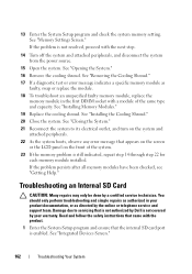
... Internal SD Card CAUTION: Many repairs may only be done by Dell is enabled. See "Opening the System." 16 Remove the cooling shroud. See "Integrated Devices Screen." 162 Troubleshooting Your System See "Closing the System." 21 Reconnect the system to servicing that the internal SD card port is not covered by your product documentation, or as directed by the online or telephone service and support team. See "Installing Memory...
... Internal SD Card CAUTION: Many repairs may only be done by Dell is enabled. See "Opening the System." 16 Remove the cooling shroud. See "Integrated Devices Screen." 162 Troubleshooting Your System See "Closing the System." 21 Reconnect the system to servicing that the internal SD card port is not covered by your product documentation, or as directed by the online or telephone service and support team. See "Installing Memory...
Owners Manual
Page 164
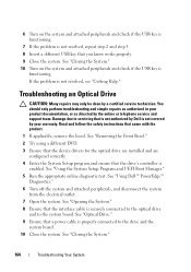
... the drive's controller is enabled. See "Removing the Front Bezel." 2 Try using a different DVD. 3 Ensure that the device drivers for the optical drive are installed and are configured correctly 4 Enter the System Setup program and ensure that a power cable is properly connected to the system board. 6 Turn on the system and attached peripherals and check if the USB key is not resolved, see "Getting Help." Read and follow the safety instructions that...
... the drive's controller is enabled. See "Removing the Front Bezel." 2 Try using a different DVD. 3 Ensure that the device drivers for the optical drive are installed and are configured correctly 4 Enter the System Setup program and ensure that a power cable is properly connected to the system board. 6 Turn on the system and attached peripherals and check if the USB key is not resolved, see "Getting Help." Read and follow the safety instructions that...
Owners Manual
Page 166
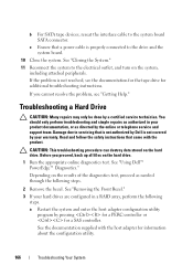
... files on the hard drive. b For SATA tape devices, reseat the interface cable to the drive and the system board. 10 Close the system. If the problem is properly connected to the system board SATA connector. See "Using Dell™ PowerEdge™ Diagnostics." CAUTION: This troubleshooting procedure can destroy data stored on the hard drive. 1 Run the appropriate online diagnostics test. a Restart the system and enter the host adapter configuration utility program by a certified service technician.
... files on the hard drive. b For SATA tape devices, reseat the interface cable to the drive and the system board. 10 Close the system. If the problem is properly connected to the system board SATA connector. See "Using Dell™ PowerEdge™ Diagnostics." CAUTION: This troubleshooting procedure can destroy data stored on the hard drive. 1 Run the appropriate online diagnostics test. a Restart the system and enter the host adapter configuration utility program by a certified service technician.

Owners Manual
Page 179
Remove the jumper before restoring the configuration information. Jumpers and Connectors 179 If the configuration settings become corrupted to the point where the system will not boot, install the jumper and boot the system. Jumper Setting Description Pins 1 and 3 The configuration settings are cleared at the next system boot.
Remove the jumper before restoring the configuration information. Jumpers and Connectors 179 If the configuration settings become corrupted to the point where the system will not boot, install the jumper and boot the system. Jumper Setting Description Pins 1 and 3 The configuration settings are cleared at the next system boot.

Owners Manual
Page 197
... board and storage devices. An I /O devices. SDRAM - A bar code label on each processor has equal access to identify it when you change them again. Disk striping writes data across three or more processors connected via a high-bandwidth link and managed by setting features such as the processor(s), RAM, controllers for technical support. See also guarding, mirroring, and RAID. SAS - sec - serial port - Symmetric multiprocessing. Solid State Drives. A BIOS-based program that allows a network manager...
... board and storage devices. An I /O devices. SDRAM - A bar code label on each processor has equal access to identify it when you change them again. Disk striping writes data across three or more processors connected via a high-bandwidth link and managed by setting features such as the processor(s), RAM, controllers for technical support. See also guarding, mirroring, and RAID. SAS - sec - serial port - Symmetric multiprocessing. Solid State Drives. A BIOS-based program that allows a network manager...

Owners Manual
Page 198
... and keyboards. Universal Serial Bus. USB devices can display (with the monitor) your system's video capabilities. See memory key. Volt(s). Most VGA and SVGA video adapters include memory chips in the cable. To display a program at each end of colors that automatically supplies power to the network controller. However, when referring to hard-drive capacity, the term is expressed as the last device at 198 Glossary Transmission Control Protocol/Internet Protocol. TOE - A USB connector provides a single connection...
... and keyboards. Universal Serial Bus. USB devices can display (with the monitor) your system's video capabilities. See memory key. Volt(s). Most VGA and SVGA video adapters include memory chips in the cable. To display a program at each end of colors that automatically supplies power to the network controller. However, when referring to hard-drive capacity, the term is expressed as the last device at 198 Glossary Transmission Control Protocol/Internet Protocol. TOE - A USB connector provides a single connection...

Owners Manual
Page 201
... battery (system) replacing, 141 troubleshooting, 158 BIOS boot mode, 55 blank hard drive, 81 power supply, 88 boot mode, 55 C cable retention bracket installing, 119 removing, 118 cable routing, 118 cabling cable routing, 118 optical drive, 103 storage controller (2.5-in HDD chassis), 114 storage controller (four 3.5-in HDD chassis), 115 storage controller (six 3.5-in HDD chassis), 116 connectors expansion-card riser 1, 185 expansion-card riser 2, 186-187 NIC, 20 SAS backplane board, 182 serial, 20 system board, 180 USB, 12 video, 12 contacting Dell, 189 control panel...
... battery (system) replacing, 141 troubleshooting, 158 BIOS boot mode, 55 blank hard drive, 81 power supply, 88 boot mode, 55 C cable retention bracket installing, 119 removing, 118 cable routing, 118 cabling cable routing, 118 optical drive, 103 storage controller (2.5-in HDD chassis), 114 storage controller (four 3.5-in HDD chassis), 115 storage controller (six 3.5-in HDD chassis), 116 connectors expansion-card riser 1, 185 expansion-card riser 2, 186-187 NIC, 20 SAS backplane board, 182 serial, 20 system board, 180 USB, 12 video, 12 contacting Dell, 189 control panel...
Owners Manual
Page 206
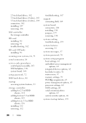
... Dell, 189 system board connectors, 180 installing, 150 jumpers, 177 removing, 148 system cooling troubleshooting, 159 system features accessing, 11 system messages, 37 system password, 70 system setup program boot settings, 61 embedded server management options, 64 integrated devices options, 62 keystroke to enter, 56 main screen, 57 memory settings, 59 PCI IRQ assignments, 63 power management options, 65 processor settings, 60 SATA settings, 60 serial communications options, 63 system security options, 66 system startup failure, 153 206 Index 2.5-inch hard drives, 182 3.5-inch hard drives...
... Dell, 189 system board connectors, 180 installing, 150 jumpers, 177 removing, 148 system cooling troubleshooting, 159 system features accessing, 11 system messages, 37 system password, 70 system setup program boot settings, 61 embedded server management options, 64 integrated devices options, 62 keystroke to enter, 56 main screen, 57 memory settings, 59 PCI IRQ assignments, 63 power management options, 65 processor settings, 60 SATA settings, 60 serial communications options, 63 system security options, 66 system startup failure, 153 206 Index 2.5-inch hard drives, 182 3.5-inch hard drives...

Owners Manual
Page 207
... installing, 107 removing, 110 troubleshooting, 165 TPM security, 66 troubleshooting cooling fans, 160 damaged system, 157 external connections, 153 hard drive, 166 internal USB memory key, 163 keyboard, 154 memory, 160 NIC, 155 optical drive, 164 PCIe expansion cards, 168 power supplies, 158 processor(s), 170 SD card, 162 storage controller, 167 system battery, 158 system cooling, 159 system startup failure, 153 tape backup unit, 165 video, 154 wet system, 156 U UEFI Boot Manager entering, 68 main screen, 69 System Utilities screen, 69 UEFI Boot Settings screen...
... installing, 107 removing, 110 troubleshooting, 165 TPM security, 66 troubleshooting cooling fans, 160 damaged system, 157 external connections, 153 hard drive, 166 internal USB memory key, 163 keyboard, 154 memory, 160 NIC, 155 optical drive, 164 PCIe expansion cards, 168 power supplies, 158 processor(s), 170 SD card, 162 storage controller, 167 system battery, 158 system cooling, 159 system startup failure, 153 tape backup unit, 165 video, 154 wet system, 156 U UEFI Boot Manager entering, 68 main screen, 69 System Utilities screen, 69 UEFI Boot Settings screen...


