

Technical Guide
Page 5
... 14 NIC Indicator LED States 17 Power Supply Connector (24 pins) Signals 25 Power Supply Connector (8 pins) Signals 26 Operating/Non-Operating Storage Requirements 26 R410 Acoustical Information 27 Supported Processor Descriptions and Features 28 Wake-Up States 34 Insert I/O Slot information 36 Descriptions of R410 Controllers 36 RAID Configurations 39 Rack Types Supported 45 Rail Adjustability Range and Rail Depth 45 Unified Server Configurator Features and Description 49 Features List for Cabled HDD Connection 38 Figure 23...
... 14 NIC Indicator LED States 17 Power Supply Connector (24 pins) Signals 25 Power Supply Connector (8 pins) Signals 26 Operating/Non-Operating Storage Requirements 26 R410 Acoustical Information 27 Supported Processor Descriptions and Features 28 Wake-Up States 34 Insert I/O Slot information 36 Descriptions of R410 Controllers 36 RAID Configurations 39 Rack Types Supported 45 Rail Adjustability Range and Rail Depth 45 Unified Server Configurator Features and Description 49 Features List for Cabled HDD Connection 38 Figure 23...

Technical Guide
Page 7
... entire portfolio. The Lifecycle Controller helps to use and maintain multiple pieces of Lifecycle Controller, Dell provides comprehensive enterprise class manageability already on the motherboard. Lifecycle Controller is delivered as system deployment, system updates, hardware configuration and diagnostics from a single intuitive interface called Unified Server Configurator (USC) in the same location for more while consuming less. This helps eliminate the need to simplify administrator tasks...
... entire portfolio. The Lifecycle Controller helps to use and maintain multiple pieces of Lifecycle Controller, Dell provides comprehensive enterprise class manageability already on the motherboard. Lifecycle Controller is delivered as system deployment, system updates, hardware configuration and diagnostics from a single intuitive interface called Unified Server Configurator (USC) in the same location for more while consuming less. This helps eliminate the need to simplify administrator tasks...

Technical Guide
Page 17
... POST or OS without driver Link, no activity Link, activity 3.7 Side Views Side views are installed in Figure 9 and Figure 10. Dual-Stacked RJ45 Connectors with the power supply. PowerEdge R410 Technical Guide Activity LED (Green) Off Off Off On (blinking at speed related to packet density) Off On (blinking at speed related to packet density) Off On (blinking at maximum port speed; Dell Amber - Alternating green and...
... POST or OS without driver Link, no activity Link, activity 3.7 Side Views Side views are installed in Figure 9 and Figure 10. Dual-Stacked RJ45 Connectors with the power supply. PowerEdge R410 Technical Guide Activity LED (Green) Off Off Off On (blinking at speed related to packet density) Off On (blinking at speed related to packet density) Off On (blinking at maximum port speed; Dell Amber - Alternating green and...
Technical Guide
Page 20
...) is used to system peripherals and the control panel. In addition, a setting in the CMOS setup disables the power button function. 3.10.6 Intrusion Alert Chassis intrusion switch is located on the bezel prevents un-authorized access to store the BitLocker keys for hard drive encryption feature in the Installing System Components chapter of the unit and provides security for toolless access to provide the Dell ID. PowerEdge R410 Technical Guide 20...
...) is used to system peripherals and the control panel. In addition, a setting in the CMOS setup disables the power button function. 3.10.6 Intrusion Alert Chassis intrusion switch is located on the bezel prevents un-authorized access to store the BitLocker keys for hard drive encryption feature in the Installing System Components chapter of the unit and provides security for toolless access to provide the Dell ID. PowerEdge R410 Technical Guide 20...
Technical Guide
Page 33
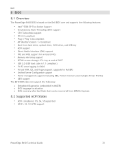
...-board NICs • Memory mirroring support • SETUP access through key at end of POST • USB 2.0 (USB boot code is 1.1 compliant) • F1/F2 error logging in CMOS • Virtual KVM, CD, and floppy support (upgrade for MASER) • Unified Server Configurator support • Power management support including DBS, Power Inventory and multiple Power Profiles • UEFI support The R410 BIOS does not support the following: Embedded Diagnostics (embedded in MASER) BIOS language localization BIOS recovery...
...-board NICs • Memory mirroring support • SETUP access through key at end of POST • USB 2.0 (USB boot code is 1.1 compliant) • F1/F2 error logging in CMOS • Virtual KVM, CD, and floppy support (upgrade for MASER) • Unified Server Configurator support • Power management support including DBS, Power Inventory and multiple Power Profiles • UEFI support The R410 BIOS does not support the following: Embedded Diagnostics (embedded in MASER) BIOS language localization BIOS recovery...

Technical Guide
Page 41
... supported. Refer to the on board SATA ports. Dell 11.5 LED Indicators LED indicator for hotswap HDD configuration LED indicator for the supported devices. Using an add-in the front of the enclosure indicates when activity occurs on any integrated SATA device connected to Table 2. 11.7 Tape Drives R410 does not support an internal backup device. Only external backup device is also activated. 11.6 Optical Drives R410 supports a SATA interface DVD-ROM or DVD+/-RW. Refer to Table 2 for cabled HDD configuration Figure 24. PowerEdge R410 Technical Guide...
... supported. Refer to the on board SATA ports. Dell 11.5 LED Indicators LED indicator for hotswap HDD configuration LED indicator for the supported devices. Using an add-in the front of the enclosure indicates when activity occurs on any integrated SATA device connected to Table 2. 11.7 Tape Drives R410 does not support an internal backup device. Only external backup device is also activated. 11.6 Optical Drives R410 supports a SATA interface DVD-ROM or DVD+/-RW. Refer to Table 2 for cabled HDD configuration Figure 24. PowerEdge R410 Technical Guide...
Technical Guide
Page 49
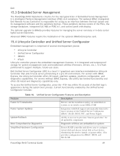
... provisioning in data center lights-out environments. For servers with display. The optional iDRAC (Integrated Dell Remote Access Controller) is a local 1:1 graphical user interface embedded on system Simplified Hardware Configuration Detects RAID controller and allows user to support multiple, future-use cases. For servers without iDRAC Express, this utility has limited functionality and offers OS install and diagnostics capabilities only. Current functionality enabled by the Unified Server Configurator includes: Table 16. PowerEdge R410 Technical Guide 49 Advanced iDRAC...
... provisioning in data center lights-out environments. For servers with display. The optional iDRAC (Integrated Dell Remote Access Controller) is a local 1:1 graphical user interface embedded on system Simplified Hardware Configuration Detects RAID controller and allows user to support multiple, future-use cases. For servers without iDRAC Express, this utility has limited functionality and offers OS install and diagnostics capabilities only. Current functionality enabled by the Unified Server Configurator includes: Table 16. PowerEdge R410 Technical Guide 49 Advanced iDRAC...

Owners Manual
Page 22
... board failure. Other failure. Diagnostic Indicator Codes (Optional) (continued) Code Causes hard drive failure. See "Troubleshooting a USB Device" on page 167. See "Getting Help" on page 146. Memory" on configuration error. No memory modules detected. Memory configuration See "Troubleshooting System error. Ensure that the diskette drive and hard drive are properly connected. Corrective Action Ensure that the diskette drive, optical drive, and hard drives are properly connected. Possible system board resource and/or system board hardware failure. See "Hard Drives...
... board failure. Other failure. Diagnostic Indicator Codes (Optional) (continued) Code Causes hard drive failure. See "Troubleshooting a USB Device" on page 167. See "Getting Help" on page 146. Memory" on configuration error. No memory modules detected. Memory configuration See "Troubleshooting System error. Ensure that the diskette drive and hard drive are properly connected. Corrective Action Ensure that the diskette drive, optical drive, and hard drives are properly connected. Possible system board resource and/or system board hardware failure. See "Hard Drives...

Owners Manual
Page 30
... an error in PCI configuration space at bus ##, device ##, function ##. E171F PCIe fatal error on Bus ## Device ## Function ## The system BIOS has reported a PCIe fatal error on page 159. connection. If the problem persists, see "Troubleshooting Expansion Cards" on a component that resides in the system, but is missing failure. E1920 iDRAC6 Upgrade optional iDRAC6 Failed. Check or bad. Remove and reseat the PCIe expansion cards. If the problem...
... an error in PCI configuration space at bus ##, device ##, function ##. E171F PCIe fatal error on Bus ## Device ## Function ## The system BIOS has reported a PCIe fatal error on page 159. connection. If the problem persists, see "Troubleshooting Expansion Cards" on a component that resides in the system, but is missing failure. E1920 iDRAC6 Upgrade optional iDRAC6 Failed. Check or bad. Remove and reseat the PCIe expansion cards. If the problem...

Owners Manual
Page 60
Option Description Processor Settings Displays information related to configure the system password and setup password features. Boot Settings See "Boot Settings Screen" on page 66. Power Management See "Power Management Screen" on page 63. SATA Settings See "SATA Settings Screen" on Management page 66. System Security Displays a screen to microprocessors (speed, cache size, and so on the PCI bus, and any installed expansion card that requires an IRQ. Select Do Not Report to suppress all error messages relating to each of the...
Option Description Processor Settings Displays information related to configure the system password and setup password features. Boot Settings See "Boot Settings Screen" on page 66. Power Management See "Power Management Screen" on page 63. SATA Settings See "SATA Settings Screen" on Management page 66. System Security Displays a screen to microprocessors (speed, cache size, and so on the PCI bus, and any installed expansion card that requires an IRQ. Select Do Not Report to suppress all error messages relating to each of the...
Owners Manual
Page 73
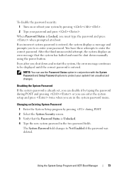
... error message that the Password Status is entered, the system displays a message and prompts you are in the two password fields. Using the System Setup Program and UEFI Boot Manager 73 You have three attempts to Not Enabled if the password was deleted. Even after you shut down manually using the power button. If an incorrect system password is Unlocked. 4 Type the new system password in the system password menu. When Password...
... error message that the Password Status is entered, the system displays a message and prompts you are in the two password fields. Using the System Setup Program and UEFI Boot Manager 73 You have three attempts to Not Enabled if the password was deleted. Even after you shut down manually using the power button. If an incorrect system password is Unlocked. 4 Type the new system password in the system password menu. When Password...
Owners Manual
Page 75
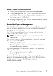
...; Installing an operating system • Running diagnostics to validate the memory, I/O devices, processors, physical disks, and other peripherals When an optional iDRAC6 Express card is an embedded utility that enables systems and storage management tasks from an embedded environment throughout the server's lifecycle. Embedded System Management The Unified Server Configurator (USC) is installed, USC provides the following features of USC are supported on page 74. Deleting or Changing an Existing Setup Password 1 Enter...
...; Installing an operating system • Running diagnostics to validate the memory, I/O devices, processors, physical disks, and other peripherals When an optional iDRAC6 Express card is an embedded utility that enables systems and storage management tasks from an embedded environment throughout the server's lifecycle. Embedded System Management The Unified Server Configurator (USC) is installed, USC provides the following features of USC are supported on page 74. Deleting or Changing an Existing Setup Password 1 Enter...

Owners Manual
Page 96
...; PCI Express Generation 1 and Generation 2 expansion cards are supported in the slots on the expansioncard riser. All other expansion cards should be installed first using the slot priority indicated. See "Closing the System" on the chassis. Installing a Non-Redundant Power Supply 1 Open the system. See "Opening the System" on page 82. 2 Place the power supply on page 83. 5 Connect the power cable to the system board, hard drive(s), and optical drive. 4 Replace the system cover...
...; PCI Express Generation 1 and Generation 2 expansion cards are supported in the slots on the expansioncard riser. All other expansion cards should be installed first using the slot priority indicated. See "Closing the System" on the chassis. Installing a Non-Redundant Power Supply 1 Open the system. See "Opening the System" on page 82. 2 Place the power supply on page 83. 5 Connect the power cable to the system board, hard drive(s), and optical drive. 4 Replace the system cover...
Owners Manual
Page 129
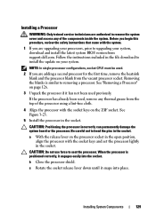
... permanently damage the system board or the processor. Before you begin this procedure, review the safety instructions that came with the system. 1 If you are adding a second processor for the first time, remove the heatsink blank and the processor blank from support.dell.com. NOTE: In single-processor configurations, socket CPU1 must be used. 2 If you are upgrading your processors, prior to upgrading your system. When...
... permanently damage the system board or the processor. Before you begin this procedure, review the safety instructions that came with the system. 1 If you are adding a second processor for the first time, remove the heatsink blank and the processor blank from support.dell.com. NOTE: In single-processor configurations, socket CPU1 must be used. 2 If you are upgrading your processors, prior to upgrading your system. When...
Owners Manual
Page 146
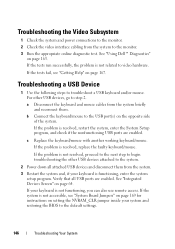
... diagnostic test. c Replace the keyboard/mouse with another working keyboard/mouse. See "Integrated Devices Screen" on page 163. See "Using Dell™ Diagnostics" on page 64. If the problem is resolved, restart the system, enter the System Setup program, and check if the nonfunctioning USB ports are enabled. Verify that all attached USB devices and disconnect them . If the tests fail, see "Getting Help" on setting the NVRAM_CLR jumper inside your keyboard is not accessible, see "System Board Jumpers...
... diagnostic test. c Replace the keyboard/mouse with another working keyboard/mouse. See "Integrated Devices Screen" on page 163. See "Using Dell™ Diagnostics" on page 64. If the problem is resolved, restart the system, enter the System Setup program, and check if the nonfunctioning USB ports are enabled. Verify that all attached USB devices and disconnect them . If the tests fail, see "Getting Help" on setting the NVRAM_CLR jumper inside your keyboard is not accessible, see "System Board Jumpers...

Owners Manual
Page 147
... the serial port. 2 Swap the serial interface cable with a comparable device. 4 Turn on the system and the serial device. Troubleshooting Your System 147 If the problem is resolved, replace the serial device. See the NIC's documentation. Troubleshooting a Serial I/O Device 1 Turn off the system and the serial device, and swap the device with another working cable, and turn on the NIC connector. If the problem persists, replace the device. Remove and reinstall the drivers if applicable. Troubleshooting a NIC 1 Run the appropriate online diagnostic test.
... the serial port. 2 Swap the serial interface cable with a comparable device. 4 Turn on the system and the serial device. Troubleshooting Your System 147 If the problem is resolved, replace the serial device. See the NIC's documentation. Troubleshooting a Serial I/O Device 1 Turn off the system and the serial device, and swap the device with another working cable, and turn on the NIC connector. If the problem persists, replace the device. Remove and reinstall the drivers if applicable. Troubleshooting a NIC 1 Run the appropriate online diagnostic test.
Owners Manual
Page 151
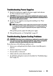
... power supply must be installed for extended periods of the following conditions exist: • System cover, cooling shroud, drive blank, or front or back filler panel is removed. • Ambient temperature is too high. • External airflow is obstructed. • Cables inside the system. Operating the system with the system Ensure that the power supply is working properly. See "Power Supplies" on page 152. Troubleshooting System Cooling Problems...
... power supply must be installed for extended periods of the following conditions exist: • System cover, cooling shroud, drive blank, or front or back filler panel is removed. • Ambient temperature is too high. • External airflow is obstructed. • Cables inside the system. Operating the system with the system Ensure that the power supply is working properly. See "Power Supplies" on page 152. Troubleshooting System Cooling Problems...

Owners Manual
Page 155
... about device drivers. 3 Reinstall the tape-backup software as instructed in the tape-backup software documentation. 4 Ensure that the drive's controller is enabled. Troubleshooting an External Tape Drive 1 Try using a different CD or DVD. 3 Enter the System Setup program and ensure that the tape drive's interface cable is properly connected to remove the system cover and access any of the components inside the system. See your tape drive documentation for the tape drive are installed...
... about device drivers. 3 Reinstall the tape-backup software as instructed in the tape-backup software documentation. 4 Ensure that the drive's controller is enabled. Troubleshooting an External Tape Drive 1 Try using a different CD or DVD. 3 Enter the System Setup program and ensure that the tape drive's interface cable is properly connected to remove the system cover and access any of the components inside the system. See your tape drive documentation for the tape drive are installed...
Owners Manual
Page 159
... system to remove the system cover and access any of the components inside the system. See "Closing the System" on page 167. If the problem persists, see the documentation for your operating system and the expansion card. See "Opening the System" on page 82. 5 Ensure that came with the system. 1 Run the appropriate online diagnostic test. See "Removing and Replacing the Optional Front Bezel...
... system to remove the system cover and access any of the components inside the system. See "Closing the System" on page 167. If the problem persists, see the documentation for your operating system and the expansion card. See "Opening the System" on page 82. 5 Ensure that came with the system. 1 Run the appropriate online diagnostic test. See "Removing and Replacing the Optional Front Bezel...

Owners Manual
Page 182
... settings remain in the event of an electrical failure. system configuration information - system memory - Because the System Setup program is running. A USB connector provides a single connection point for video adapters with the monitor) your system's integral components, such as mice and keyboards. Volt(s). uplink port - USB memory key - VDC - system board - TCP/IP - VAC - Video graphics array. Data stored in the cable. A BIOS-based program that plugs into an expansion slot. 182 Glossary Transmission Control...
... settings remain in the event of an electrical failure. system configuration information - system memory - Because the System Setup program is running. A USB connector provides a single connection point for video adapters with the monitor) your system's integral components, such as mice and keyboards. Volt(s). uplink port - USB memory key - VDC - system board - TCP/IP - VAC - Video graphics array. Data stored in the cable. A BIOS-based program that plugs into an expansion slot. 182 Glossary Transmission Control...


