
Glossary
Page 6
... not lose its contents when you turn off your system, the POST tests various system components such as 640 x 480, is associated with multiple power outlets that communicates with managed objects and accesses data and event notifications from a variety of a CIM schema that provides electrical power to a system. Redundant information that...
... not lose its contents when you turn off your system, the POST tests various system components such as 640 x 480, is associated with multiple power outlets that communicates with managed objects and accesses data and event notifications from a variety of a CIM schema that provides electrical power to a system. Redundant information that...
User Manual
Page 6
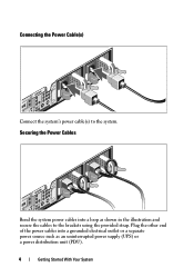
Securing the Power Cables Bend the system power cables into a grounded electrical outlet or a separate power source such as shown in the illustration and secure the cables to the system. Connecting the Power Cable(s) Connect the system's power cable(s) to the brackets using the provided strap. Plug the other end of the power cables into a loop as an uninterrupted power supply (UPS) or a power distribution unit (PDU). 4 Getting Started With Your System
Securing the Power Cables Bend the system power cables into a grounded electrical outlet or a separate power source such as shown in the illustration and secure the cables to the system. Connecting the Power Cable(s) Connect the system's power cable(s) to the brackets using the provided strap. Plug the other end of the power cables into a loop as an uninterrupted power supply (UPS) or a power distribution unit (PDU). 4 Getting Started With Your System
Hardware Owner's Manual
Page 34
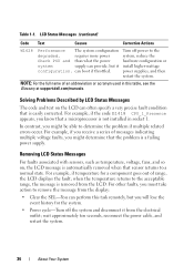
..., you might be able to the acceptable range, the message is not installed in this task remotely, but it from the electrical outlet; LCD Status Messages (continued) Code Text Causes Corrective Actions W1628 Performance The system configuration Turn off the system and disconnect it install ...associated with sensors, such as temperature, voltage, fans, and so on the LCD can perform this table, see the Glossary at support.dell.com/manuals. Table 1-1. requires more power system, reduce the Check PSU and than what the power hardware configuration or system supply can boot...
..., you might be able to the acceptable range, the message is not installed in this task remotely, but it from the electrical outlet; LCD Status Messages (continued) Code Text Causes Corrective Actions W1628 Performance The system configuration Turn off the system and disconnect it install ...associated with sensors, such as temperature, voltage, fans, and so on the LCD can perform this table, see the Glossary at support.dell.com/manuals. Table 1-1. requires more power system, reduce the Check PSU and than what the power hardware configuration or system supply can boot...
Hardware Owner's Manual
Page 76
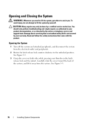
..., and disconnect the system from the system. Carefully slide the cover toward the back of the system, and lift it away from the electrical outlet and peripherals. 2 Rotate the latch release lock counter clockwise to servicing that came with the product. See Figure 3-3. 3 Grasp the cover on...authorized in your product documentation, or as directed by a certified service technician. Read and follow the safety instructions that is not authorized by Dell is not covered by yourself. Damage due to the unlocked position. To avoid injury, do not attempt to assist you need to lift ...
..., and disconnect the system from the system. Carefully slide the cover toward the back of the system, and lift it away from the electrical outlet and peripherals. 2 Rotate the latch release lock counter clockwise to servicing that came with the product. See Figure 3-3. 3 Grasp the cover on...authorized in your product documentation, or as directed by a certified service technician. Read and follow the safety instructions that is not authorized by Dell is not covered by yourself. Damage due to the unlocked position. To avoid injury, do not attempt to assist you need to lift ...
Hardware Owner's Manual
Page 78
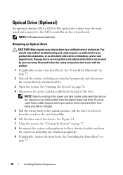
... turn the system on including any attached peripherals, and disconnect the system from its electrical outlet. 3 Open the system. NOTE: Note the routing of the power and data cables underneath the tabs on the metal standoffs. 6 Lift the drive...Turn off the system, including any attached peripherals. 9 If applicable, replace the front bezel. Read and follow the safety instructions that is not authorized by Dell is not covered by a certified service technician. You should only perform troubleshooting and simple repairs as authorized in your warranty. See "Front Bezel (Optional)" ...
... turn the system on including any attached peripherals, and disconnect the system from its electrical outlet. 3 Open the system. NOTE: Note the routing of the power and data cables underneath the tabs on the metal standoffs. 6 Lift the drive...Turn off the system, including any attached peripherals. 9 If applicable, replace the front bezel. Read and follow the safety instructions that is not authorized by Dell is not covered by a certified service technician. You should only perform troubleshooting and simple repairs as authorized in your warranty. See "Front Bezel (Optional)" ...

Hardware Owner's Manual
Page 80
... product. 1 If applicable, remove the front bezel. See "Installing the Front Bezel" on the side of the drive and to prevent them from its electrical outlet and turn the system on page 77. 9 If applicable, replace the front bezel. Installing an Optical Drive CAUTION: Many repairs may only be done by... Dell is seated firmly and the release latch snaps into the notches until it is not covered by your product documentation, or as directed by the ...
... product. 1 If applicable, remove the front bezel. See "Installing the Front Bezel" on the side of the drive and to prevent them from its electrical outlet and turn the system on page 77. 9 If applicable, replace the front bezel. Installing an Optical Drive CAUTION: Many repairs may only be done by... Dell is seated firmly and the release latch snaps into the notches until it is not covered by your product documentation, or as directed by the ...
Hardware Owner's Manual
Page 88
... support team. The brackets also keep dust and dirt out of the system. Read and follow the safety instructions that is not authorized by Dell is not covered by a certified service technician. NOTE: You must install a filler bracket over an empty expansion slot to its edges and ... 4 Lift the expansion-card latch. You should only perform troubleshooting and simple repairs as directed by its electrical outlet and turn the system on page 76. 3 Disconnect all cables from the electrical outlet. 2 Open the system. Damage due to servicing that came with the product. 1 Turn off the system,...
... support team. The brackets also keep dust and dirt out of the system. Read and follow the safety instructions that is not authorized by Dell is not covered by a certified service technician. NOTE: You must install a filler bracket over an empty expansion slot to its edges and ... 4 Lift the expansion-card latch. You should only perform troubleshooting and simple repairs as directed by its electrical outlet and turn the system on page 76. 3 Disconnect all cables from the electrical outlet. 2 Open the system. Damage due to servicing that came with the product. 1 Turn off the system,...
Hardware Owner's Manual
Page 89
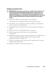
For instructions, see the documentation accompanying the card. 2 Turn off the system, including any attached peripherals, and disconnect the system from the electrical outlet. 3 If applicable, remove the front bezel. See Figure 3-8. 6 Holding the expansion card by a certified service technician. edge connector aligns with the ...only be done by its edges, position the card so that the card- You should only perform troubleshooting and simple repairs as directed by Dell is fully seated. 8 Replace the expansion-card latch. See "Opening the System" on page 75. 4 Open the system. See Figure ...
For instructions, see the documentation accompanying the card. 2 Turn off the system, including any attached peripherals, and disconnect the system from the electrical outlet. 3 If applicable, remove the front bezel. See Figure 3-8. 6 Holding the expansion card by a certified service technician. edge connector aligns with the ...only be done by its edges, position the card so that the card- You should only perform troubleshooting and simple repairs as directed by Dell is fully seated. 8 Replace the expansion-card latch. See "Opening the System" on page 75. 4 Open the system. See Figure ...
Hardware Owner's Manual
Page 90
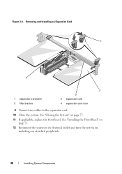
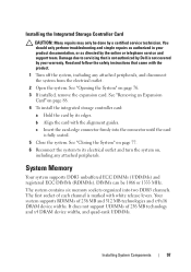
Figure 3-8. See "Closing the System" on , including any cables to the expansion card. 10 Close the system. See "Installing the Front Bezel" on page 75. 12 Reconnect the system to its electrical outlet and turn the system on page 77. 11 If applicable, replace the front bezel. Removing and Installing an Expansion Card 1 4 1 expansion-card latch 3 filler bracket 2 3 2 expansion card 4 expansion-card riser 9 Connect any attached peripherals. 90 Installing System Components
Figure 3-8. See "Closing the System" on , including any cables to the expansion card. 10 Close the system. See "Installing the Front Bezel" on page 75. 12 Reconnect the system to its electrical outlet and turn the system on page 77. 11 If applicable, replace the front bezel. Removing and Installing an Expansion Card 1 4 1 expansion-card latch 3 filler bracket 2 3 2 expansion card 4 expansion-card riser 9 Connect any attached peripherals. 90 Installing System Components
Hardware Owner's Manual
Page 91
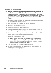
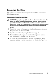
...the release tab and lift the expansion-card riser from the expansion-card slot. Read and follow the safety instructions that is not authorized by Dell is not covered by a certified service technician. See Figure 3-9. Damage due to servicing that came with the product. 1 Turn off the... system, including any attached peripherals, and disconnect the system from the electrical outlet. 2 Open the system. Removing an Expansion-Card Riser CAUTION: Many repairs may only be done by your product documentation, or as authorized in...
...the release tab and lift the expansion-card riser from the expansion-card slot. Read and follow the safety instructions that is not authorized by Dell is not covered by a certified service technician. See Figure 3-9. Damage due to servicing that came with the product. 1 Turn off the... system, including any attached peripherals, and disconnect the system from the electrical outlet. 2 Open the system. Removing an Expansion-Card Riser CAUTION: Many repairs may only be done by your product documentation, or as authorized in...

Hardware Owner's Manual
Page 93
... and simple repairs as authorized in your warranty. Damage due to servicing that is not authorized by Dell is facilitated by your product documentation, or as directed by the online or telephone service and support ...the safety instructions that came with the riser guide posts on the system board. Ensure that is not authorized by Dell is fully seated. 3 If applicable, reinstall the expansion card. See "Installing an Expansion Card" on , including...very hot during normal operation. Damage due to its electrical outlet and turn the system on page 89. 4 Close the system.
... and simple repairs as authorized in your warranty. Damage due to servicing that is not authorized by Dell is facilitated by your product documentation, or as directed by the online or telephone service and support ...the safety instructions that came with the riser guide posts on the system board. Ensure that is not authorized by Dell is fully seated. 3 If applicable, reinstall the expansion card. See "Installing an Expansion Card" on , including...very hot during normal operation. Damage due to its electrical outlet and turn the system on page 89. 4 Close the system.
Hardware Owner's Manual
Page 94
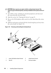
... cables routed over the shroud from the system board. 4 Hold the touch points and gently lift the shroud straight up and away from the electrical outlet. 2 Open the system. Figure 3-10. CAUTION: Never operate your system with the cooling shroud removed. See Figure 3-10. The system may get overheated quickly, resulting...
... cables routed over the shroud from the system board. 4 Hold the touch points and gently lift the shroud straight up and away from the electrical outlet. 2 Open the system. Figure 3-10. CAUTION: Never operate your system with the cooling shroud removed. See Figure 3-10. The system may get overheated quickly, resulting...
Hardware Owner's Manual
Page 95
... certified service technician. See "Removing an Expansion Card" on page 88. 5 Press down until all edges are secured to servicing that is not authorized by Dell is not covered by your warranty. Installing the Cooling Shroud 1 Orient the cooling shroud with the numbered fan bays as a guide. 2 Align the cooling ...system board. 3 Push the cooling shroud down on the card retention tab and pull the blue release tab. 6 Remove the card from the electrical outlet. 2 If applicable, remove the front bezel. See "Opening and Closing the System" on page 76. 5 Reconnect the system to its electrical...
... certified service technician. See "Removing an Expansion Card" on page 88. 5 Press down until all edges are secured to servicing that is not authorized by Dell is not covered by your warranty. Installing the Cooling Shroud 1 Orient the cooling shroud with the numbered fan bays as a guide. 2 Align the cooling ...system board. 3 Push the cooling shroud down on the card retention tab and pull the blue release tab. 6 Remove the card from the electrical outlet. 2 If applicable, remove the front bezel. See "Opening and Closing the System" on page 76. 5 Reconnect the system to its electrical...

Hardware Owner's Manual
Page 96
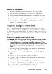
See "Installing the Front Bezel" on page 75. 9 Reconnect the system to its electrical outlet and turn the system on, including any attached peripherals. Removing and Installing the Integrated Storage Controller Card 1 2 4 3 1 integrated storage controller card connector 3 release tab 2 integrated storage controller card 4 alignment guides (2) 96 Installing System Components Figure 3-11. 8 If applicable, replace the front bezel.
See "Installing the Front Bezel" on page 75. 9 Reconnect the system to its electrical outlet and turn the system on, including any attached peripherals. Removing and Installing the Integrated Storage Controller Card 1 2 4 3 1 integrated storage controller card connector 3 release tab 2 integrated storage controller card 4 alignment guides (2) 96 Installing System Components Figure 3-11. 8 If applicable, replace the front bezel.
Hardware Owner's Manual
Page 97
... online or telephone service and support team. See "Opening the System" on , including any attached peripherals, and disconnect the system from the electrical outlet. 2 Open the system. b Align the card with the product. 1 Turn off the system, including any attached peripherals. See "Removing an Expansion... each channel is fully seated. 5 Close the system. Read and follow the safety instructions that is not authorized by Dell is not covered by its electrical outlet and turn the system on page 76. 3 If installed, remove the expansion card. Damage due to its edges. ...
... online or telephone service and support team. See "Opening the System" on , including any attached peripherals, and disconnect the system from the electrical outlet. 2 Open the system. b Align the card with the product. 1 Turn off the system, including any attached peripherals. See "Removing an Expansion... each channel is fully seated. 5 Close the system. Read and follow the safety instructions that is not authorized by Dell is not covered by its electrical outlet and turn the system on page 76. 3 If installed, remove the expansion card. Damage due to its edges. ...

Hardware Owner's Manual
Page 101
Damage due to servicing that came with the product. 1 Turn off the system, including any attached peripherals, and disconnect the system from the electrical outlet. 2 Open the system. See "Removing the Cooling Shroud" on page 76. 3 Remove the cooling shroud. See Figure 6-1. 5 Press the ejectors on either ... hot to touch for the memory modules to cool before handling them. Read and follow the safety instructions that is not authorized by Dell is not covered by the card edges and avoid touching the components on the memory module. Handle the memory modules by your product ...
Damage due to servicing that came with the product. 1 Turn off the system, including any attached peripherals, and disconnect the system from the electrical outlet. 2 Open the system. See "Removing the Cooling Shroud" on page 76. 3 Remove the cooling shroud. See Figure 6-1. 5 Press the ejectors on either ... hot to touch for the memory modules to cool before handling them. Read and follow the safety instructions that is not authorized by Dell is not covered by the card edges and avoid touching the components on the memory module. Handle the memory modules by your product ...

Hardware Owner's Manual
Page 103
... the System" on page 154. See Figure 6-1. 5 Press down . See "Closing the System" on page 77. 8 Reconnect the system to its electrical outlet and turn the system on, including any attached peripherals. See "Running the Embedded System Diagnostics" on page 76. 3 Remove the cooling shroud. Removing Memory Modules...test in your product documentation, or as authorized in the system diagnostics. Read and follow the safety instructions that is not authorized by Dell is incorrect, one or more of the socket. Handle each end of the socket until the memory module pops out of the memory...
... the System" on page 154. See Figure 6-1. 5 Press down . See "Closing the System" on page 77. 8 Reconnect the system to its electrical outlet and turn the system on, including any attached peripherals. See "Running the Embedded System Diagnostics" on page 76. 3 Remove the cooling shroud. Removing Memory Modules...test in your product documentation, or as authorized in the system diagnostics. Read and follow the safety instructions that is not authorized by Dell is incorrect, one or more of the socket. Handle each end of the socket until the memory module pops out of the memory...

Hardware Owner's Manual
Page 104
... supplies, and memory modules. Removing a Cooling Fan WARNING: The cooling fan can continue to stop spinning before removing it away from its electrical outlet. 2 Open the system. NOTE: Hot-swap removal or installation of a problem with the product. Cooling Fans Your system contains five single-motor... particular fan, the fan number is not covered by a certified service technician. Read and follow the safety instructions that is not authorized by Dell is referenced by noting the fan numbers on page 93. 4 Disconnect the fan's power cable from the system. See "Cooling Shroud" on ...
... supplies, and memory modules. Removing a Cooling Fan WARNING: The cooling fan can continue to stop spinning before removing it away from its electrical outlet. 2 Open the system. NOTE: Hot-swap removal or installation of a problem with the product. Cooling Fans Your system contains five single-motor... particular fan, the fan number is not covered by a certified service technician. Read and follow the safety instructions that is not authorized by Dell is referenced by noting the fan numbers on page 93. 4 Disconnect the fan's power cable from the system. See "Cooling Shroud" on ...
Hardware Owner's Manual
Page 106
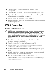
...the product. 1 Turn off the system, including any attached peripherals. See Figure 3-13. 3 Connect the fan's power cable to its electrical outlet and turn the system on, including any attached peripherals, and disconnect the system from the expansion-card slot. iDRAC6 Express Card Installing an iDRAC6 Express... on page 88. 4 Insert the notch on the system board. 4 Replace the cooling shroud or power distribution board shroud as directed by Dell is fully seated, the plastic standoff tab snaps over the edge of the holder. 106 Installing System Components See Figure 3-14. You should only...
...the product. 1 Turn off the system, including any attached peripherals. See Figure 3-13. 3 Connect the fan's power cable to its electrical outlet and turn the system on, including any attached peripherals, and disconnect the system from the expansion-card slot. iDRAC6 Express Card Installing an iDRAC6 Express... on page 88. 4 Insert the notch on the system board. 4 Replace the cooling shroud or power distribution board shroud as directed by Dell is fully seated, the plastic standoff tab snaps over the edge of the holder. 106 Installing System Components See Figure 3-14. You should only...
Hardware Owner's Manual
Page 107
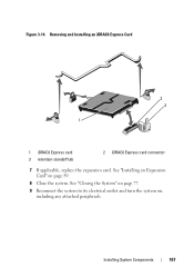
See "Installing an Expansion Card" on , including any attached peripherals. Removing and Installing an iDRAC6 Express Card 2 3 1 1 iDRAC6 Express card 3 retention standoff tab 2 iDRAC6 Express card connector 7 If applicable, replace the expansion card. Installing System Components 107 See "Closing the System" on page 77. 9 Reconnect the system to its electrical outlet and turn the system on page 89. 8 Close the system. Figure 3-14.
See "Installing an Expansion Card" on , including any attached peripherals. Removing and Installing an iDRAC6 Express Card 2 3 1 1 iDRAC6 Express card 3 retention standoff tab 2 iDRAC6 Express card connector 7 If applicable, replace the expansion card. Installing System Components 107 See "Closing the System" on page 77. 9 Reconnect the system to its electrical outlet and turn the system on page 89. 8 Close the system. Figure 3-14.