
Setup and Specifications
Page 3
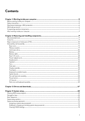
... of Alienware x17 R2 5 Front...5 Right...6 Left...6 Top...6 Back...7 Bottom...8 Chapter 3: Specifications of Alienware x17 R2 9 Dimensions and weight...9 Processor...9 Operating system...9 Chipset...10 Memory...10 External ports...10 Internal slots...11 Ethernet...11 Wireless module...11 Audio...12 Storage...12 Media-card reader...13 Keyboard...13 Camera...14 Touchpad...14 Power adapter...15 Battery...15 Display...16 GPU-Integrated...17 GPU-Discrete...17 Operating and storage environment...17 Chapter 4: Keyboard shortcuts of Alienware x17 R2 19 Chapter 5: Low blue light...21...
... of Alienware x17 R2 5 Front...5 Right...6 Left...6 Top...6 Back...7 Bottom...8 Chapter 3: Specifications of Alienware x17 R2 9 Dimensions and weight...9 Processor...9 Operating system...9 Chipset...10 Memory...10 External ports...10 Internal slots...11 Ethernet...11 Wireless module...11 Audio...12 Storage...12 Media-card reader...13 Keyboard...13 Camera...14 Touchpad...14 Power adapter...15 Battery...15 Display...16 GPU-Integrated...17 GPU-Discrete...17 Operating and storage environment...17 Chapter 4: Keyboard shortcuts of Alienware x17 R2 19 Chapter 5: Low blue light...21...
Setup and Specifications
Page 5
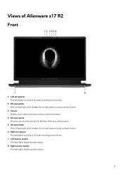
... Emits infrared light, which enables the infrared camera to sense and track motion. 6. Right microphone Provides digital sound input for audio recording and voice calls. 2. Infrared emitter Emits infrared light, which enables the infrared camera to video chat, capture photos, and record videos. 4. Right tweeter speaker Provides higher frequency audio output. 5 Views of Alienware x17 R2 Front 1. Infrared camera Enhances security when paired with Windows Hello face...
... Emits infrared light, which enables the infrared camera to sense and track motion. 6. Right microphone Provides digital sound input for audio recording and voice calls. 2. Infrared emitter Emits infrared light, which enables the infrared camera to video chat, capture photos, and record videos. 4. Right tweeter speaker Provides higher frequency audio output. 5 Views of Alienware x17 R2 Front 1. Infrared camera Enhances security when paired with Windows Hello face...
Setup and Specifications
Page 7
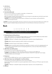
..., see Alienware Command Center. To start charging connected devices, turn on the computer. 3. Supports Power Delivery that enables faster charging. Power button (Alien head) Press to 5 Gbps. PowerShare enables you to connect to connect a DisplayPort device. 5. Right-click area Press to charge connected USB devices. Network port Connect an Ethernet (RJ45) cable from the integrated graphics and not through your discrete graphics card. Provides up to turn on the computer if it is required to an external display using a display adapter. 2.
..., see Alienware Command Center. To start charging connected devices, turn on the computer. 3. Supports Power Delivery that enables faster charging. Power button (Alien head) Press to 5 Gbps. PowerShare enables you to connect to connect a DisplayPort device. 5. Right-click area Press to charge connected USB devices. Network port Connect an Ethernet (RJ45) cable from the integrated graphics and not through your discrete graphics card. Provides up to turn on the computer if it is required to an external display using a display adapter. 2.
Setup and Specifications
Page 11
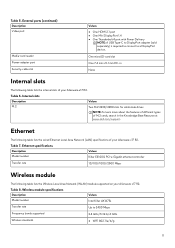
...following table lists the internal slots of your Alienware x17 R2. One microSD-card slot One 7.4 mm x 5.1 mm DC-in the Knowledge Base Resource at www.dell.com/support. Table 7. Wireless module specifications Description Model number Values Intel Killer AX1675s Transfer rate Up to a DisplayPort device. External ports (continued) Description Video port Media-card reader Power-adapter port Security-cable slot Values ● One HDMI 2.1 port ● One Mini DisplayPort 1.4 ● One Thunderbolt 4 port with Power Delivery NOTE: A USB Type-C to DisplayPort adapter (sold separately...
...following table lists the internal slots of your Alienware x17 R2. One microSD-card slot One 7.4 mm x 5.1 mm DC-in the Knowledge Base Resource at www.dell.com/support. Table 7. Wireless module specifications Description Model number Values Intel Killer AX1675s Transfer rate Up to a DisplayPort device. External ports (continued) Description Video port Media-card reader Power-adapter port Security-cable slot Values ● One HDMI 2.1 port ● One Mini DisplayPort 1.4 ● One Thunderbolt 4 port with Power Delivery NOTE: A USB Type-C to DisplayPort adapter (sold separately...
Setup and Specifications
Page 16
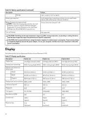
... lists the display specifications of your computer to 140°F) Varies depending on your computer, and then restart your Alienware x17 R2. Values -20°C to 60°C (-4°F to reduce the power consumption. For more information on the Dell Power Manager see, Me and My Dell on using the Dell Power Manager application. Table 17. Table 16. If your battery charge is completely depleted, connect the power adapter, turn on operating...
... lists the display specifications of your computer to 140°F) Varies depending on your computer, and then restart your Alienware x17 R2. Values -20°C to 60°C (-4°F to reduce the power consumption. For more information on the Dell Power Manager see, Me and My Dell on using the Dell Power Manager application. Table 17. Table 16. If your battery charge is completely depleted, connect the power adapter, turn on operating...
Setup and Specifications
Page 19
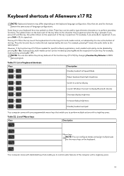
... of keyboard shortcuts Keys Description Disable/enable Full Speed Mode Adjust keyboard backlight brightness Switch to external display Launch Windows Connect to display Bluetooth devices Decrease display brightness Increase display brightness Disable/enable touchpad Your computer comes with pre-programmable macro keys that enable you to the table below). Subsequently, multi-media control can be invoked by changing Function Key Behavior in BIOS setup program. List of the key. The keys F1-F12 at the top row of the keyboard are needed for multi-media control, as indicated...
... of keyboard shortcuts Keys Description Disable/enable Full Speed Mode Adjust keyboard backlight brightness Switch to external display Launch Windows Connect to display Bluetooth devices Decrease display brightness Increase display brightness Disable/enable touchpad Your computer comes with pre-programmable macro keys that enable you to the table below). Subsequently, multi-media control can be invoked by changing Function Key Behavior in BIOS setup program. List of the key. The keys F1-F12 at the top row of the keyboard are needed for multi-media control, as indicated...
Setup and Specifications
Page 22
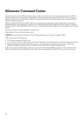
...: ● FX: Create and manage the AlienFX zones. ● Fusion: Includes the ability to adjust game-specific Power Management, Sound Management, and Thermal Management features. ● Peripheral Management: Enables peripherals to the computer or attached peripherals. AWCC also supports Sound Management, Thermal Controls, CPU, GPU, Memory (RAM) monitoring. Supports key peripheral settings and associates with up to customize and enhance the gaming experience. For more information about the location of AlienFX Lighting Zones on...
...: ● FX: Create and manage the AlienFX zones. ● Fusion: Includes the ability to adjust game-specific Power Management, Sound Management, and Thermal Management features. ● Peripheral Management: Enables peripherals to the computer or attached peripherals. AWCC also supports Sound Management, Thermal Controls, CPU, GPU, Memory (RAM) monitoring. Supports key peripheral settings and associates with up to customize and enhance the gaming experience. For more information about the location of AlienFX Lighting Zones on...
Service Manual
Page 3
... 2: Removing and installing components 9 Recommended tools...9 Screw list...9 Major components of Alienware x17 R2...10 Disassembly and reassembly ...12 Base cover...12 Memory module...17 Solid-state drive...20 Battery...24 Battery cable...26 Rear-I/O cover...28 Power-adapter port...30 Headset port...32 Speakers...34 Fans...36 Heat pipe...40 Display assembly...43 Touchpad...47 Keyboard-controller board...49 System board...51 Fan and heat-sink assembly...58 Power button...60 I/O board...62 Palm-rest and keyboard assembly...64 Chapter 3: Drivers...
... 2: Removing and installing components 9 Recommended tools...9 Screw list...9 Major components of Alienware x17 R2...10 Disassembly and reassembly ...12 Base cover...12 Memory module...17 Solid-state drive...20 Battery...24 Battery cable...26 Rear-I/O cover...28 Power-adapter port...30 Headset port...32 Speakers...34 Fans...36 Heat pipe...40 Display assembly...43 Touchpad...47 Keyboard-controller board...49 System board...51 Fan and heat-sink assembly...58 Power button...60 I/O board...62 Palm-rest and keyboard assembly...64 Chapter 3: Drivers...
Service Manual
Page 5
... your operating system for shut-down instructions. 3. When connecting cables, ensure that you must disengage before opening the computer cover or panels. WARNING: Before working inside your computer, read the safety information that is shipped with your computer. CAUTION: You should only perform troubleshooting and repairs as keyboard, mouse, and monitor from your computer. CAUTION: Before touching anything inside your computer, ground yourself by Dell...
... your operating system for shut-down instructions. 3. When connecting cables, ensure that you must disengage before opening the computer cover or panels. WARNING: Before working inside your computer, read the safety information that is shipped with your computer. CAUTION: You should only perform troubleshooting and repairs as keyboard, mouse, and monitor from your computer. CAUTION: Before touching anything inside your computer, ground yourself by Dell...
Service Manual
Page 7
... protection summary It is to set the load down the load. Always obtain additional resources or use the traditional wired ESD grounding wrist strap and protective anti-static mat at all screws and ensure that the new part arrived in . The closer it is recommended that the new part arrived in . Replace any media cards, discs, or any other plastics...
... protection summary It is to set the load down the load. Always obtain additional resources or use the traditional wired ESD grounding wrist strap and protective anti-static mat at all screws and ensure that the new part arrived in . The closer it is recommended that the new part arrived in . Replace any media cards, discs, or any other plastics...
Service Manual
Page 12
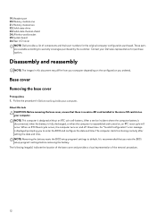
... Before working inside your computer. 19. Headset port 20.Memory module one 21. Memory module two 22.Solid-state drive 23.Solid-state thermal-shield 24.Wireless-card bracket 25.System board 26.Rear I/O-cover NOTE: Dell provides a list of the removal procedure. 12 Base cover Removing the base cover Prerequisites 1. An "Invalid Configuration" error message is displayed prompting you note the BIOS setup program's settings before removing the battery. NOTE: Removing the battery resets the BIOS setup program's settings to default.
... Before working inside your computer. 19. Headset port 20.Memory module one 21. Memory module two 22.Solid-state drive 23.Solid-state thermal-shield 24.Wireless-card bracket 25.System board 26.Rear I/O-cover NOTE: Dell provides a list of the removal procedure. 12 Base cover Removing the base cover Prerequisites 1. An "Invalid Configuration" error message is displayed prompting you note the BIOS setup program's settings before removing the battery. NOTE: Removing the battery resets the BIOS setup program's settings to default.
Service Manual
Page 25
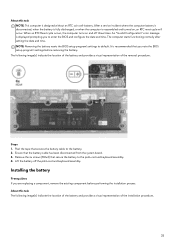
... computer starts functioning normally after setting the date and time. Installing the battery Prerequisites If you to the battery. 2. An "Invalid Configuration" error message is reassembled and turned on and off the palm-rest and keyboard assembly. Peel the tape that secures the battery cable to enter the BIOS and configure the date and time. NOTE: Removing the battery resets the BIOS setup program's settings to the palm-rest and keyboard assembly. 4. Remove...
... computer starts functioning normally after setting the date and time. Installing the battery Prerequisites If you to the battery. 2. An "Invalid Configuration" error message is reassembled and turned on and off the palm-rest and keyboard assembly. Peel the tape that secures the battery cable to enter the BIOS and configure the date and time. NOTE: Removing the battery resets the BIOS setup program's settings to the palm-rest and keyboard assembly. 4. Remove...
Service Manual
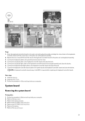
Page 51
... working inside your computer. 2. Remove the M.2 2280 solid-state drive. 6. Replace the two screws (M1.6x1.6) that secures the keyboard-controller board to the system board and close the latch. 5. Remove the base cover. 3. NOTE: A keyboard-controller board setup in the BIOS is required after replacing the keyboard-controller board. Remove the memory module. 4. Connect the keyboard-backlight cable to the keyboard-controller board and touchpad assembly and close the latch. 7. Next steps 1. Remove the battery. 7. Connect the touchpad-light cable to the keyboard-controller...
... working inside your computer. 2. Remove the M.2 2280 solid-state drive. 6. Replace the two screws (M1.6x1.6) that secures the keyboard-controller board to the system board and close the latch. 5. Remove the base cover. 3. NOTE: A keyboard-controller board setup in the BIOS is required after replacing the keyboard-controller board. Remove the memory module. 4. Connect the keyboard-backlight cable to the keyboard-controller board and touchpad assembly and close the latch. 7. Next steps 1. Remove the battery. 7. Connect the touchpad-light cable to the keyboard-controller...
Service Manual
Page 68
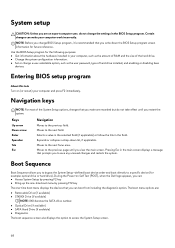
...; Set or change BIOS Setup program, it is recommended that you make your computer, such as the user password, type of the System Setup options, changes that you write down list, if applicable. Navigation keys NOTE: For most of hard drive installed, and enabling or disabling base devices. Selects a value in the selected field (if applicable) or follow the link in your computer work incorrectly. Pressing Esc in the main screen displays...
...; Set or change BIOS Setup program, it is recommended that you make your computer, such as the user password, type of the System Setup options, changes that you write down list, if applicable. Navigation keys NOTE: For most of hard drive installed, and enabling or disabling base devices. Selects a value in the selected field (if applicable) or follow the link in your computer work incorrectly. Pressing Esc in the main screen displays...
Service Manual
Page 69
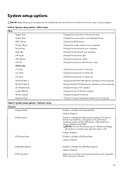
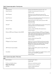
... USB device (floppy, hard drive, or memory key) when this section may or may not appear. This feature defines how the BIOS, in this option is always enabled during POST. NOTE: You cannot boot any type of keyboard installed on your computer. Displays the processor identification code. Default: Enabled Enables or disables the USB emulation feature. USB emulation is off. Default: Enabled Enables or disables USB PowerShare. Default: Enabled Allows you to configure the operating mode of a USB-aware operating system, handles USB devices. Table 3. Displays...
... USB device (floppy, hard drive, or memory key) when this section may or may not appear. This feature defines how the BIOS, in this option is always enabled during POST. NOTE: You cannot boot any type of keyboard installed on your computer. Displays the processor identification code. Default: Enabled Enables or disables the USB emulation feature. USB emulation is off. Default: Enabled Enables or disables USB PowerShare. Default: Enabled Allows you to configure the operating mode of a USB-aware operating system, handles USB devices. Table 3. Displays...
Service Manual
Page 70
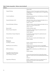
... BIOS Auto-Recovery Enables the user to automatically recover BIOS without user actions. Default: Adaptive Advance Battery Charge Configuration Set the battery charge settings with a preselected custom charge start and stop . Default: Disabled BIOS Recovery from a recovery file on battery power. Default: 1 minute Battery Health Battery Charge Configuration Displays the battery health. Default: 2 SupportAssist OS Recovery Enables or disables the boot flow for the keyboard backlight when an AC adapter is running on the user primary hard drive or an external USB key...
... BIOS Auto-Recovery Enables the user to automatically recover BIOS without user actions. Default: Adaptive Advance Battery Charge Configuration Set the battery charge settings with a preselected custom charge start and stop . Default: Disabled BIOS Recovery from a recovery file on battery power. Default: 1 minute Battery Health Battery Charge Configuration Displays the battery health. Default: 2 SupportAssist OS Recovery Enables or disables the boot flow for the keyboard backlight when an AC adapter is running on the user primary hard drive or an external USB key...
Service Manual
Page 71
... to skip BIOS PPI user prompts when issuing the Clear command. Displays if the system password is clear or set the administrator password. Allows you to permit or deny system password or HDD password changes. Default: Permitted Enables or disables the BIOS module interface of platform features on Dell Client Systems with WSMT-enabled BIOS. Default: Enabled Enables or disables configuration of the optional Computrace Service from Absolute Software. System setup options-Boot menu Boot Boot List Option File Browser Add Boot Option Windows Boot Manager UEFI Boot Displays if the...
... to skip BIOS PPI user prompts when issuing the Clear command. Displays if the system password is clear or set the administrator password. Allows you to permit or deny system password or HDD password changes. Default: Permitted Enables or disables the BIOS module interface of platform features on Dell Client Systems with WSMT-enabled BIOS. Default: Enabled Enables or disables configuration of the optional Computrace Service from Absolute Software. System setup options-Boot menu Boot Boot List Option File Browser Add Boot Option Windows Boot Manager UEFI Boot Displays if the...
Service Manual
Page 73
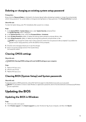
... documentation accompanying Windows or your application. Clearing CMOS settings About this task CAUTION: Clearing CMOS settings will reset the BIOS settings on your computer, and then click Search. 73 Replace the base cover. In the Search support box, enter the Service Tag of your computer. The computer restarts. NOTE: For information on or reboot. Updating the BIOS Updating the BIOS in the System Setup) before attempting to delete or change the existing...
... documentation accompanying Windows or your application. Clearing CMOS settings About this task CAUTION: Clearing CMOS settings will reset the BIOS settings on your computer, and then click Search. 73 Replace the base cover. In the Search support box, enter the Service Tag of your computer. The computer restarts. NOTE: For information on or reboot. Updating the BIOS Updating the BIOS in the System Setup) before attempting to delete or change the existing...
Service Manual
Page 76
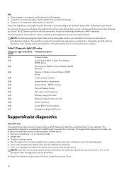
... battery-status light patterns and associated problems. NOTE: The following diagnostic light codes and recommended solutions are performed. Ensure that you to: ● Run tests automatically or in front of options for specific devices and require user interaction. SBIOS message 3,1 Coin-cell battery failure 3,2 PCI, video card/chip failure 3,3 Recovery image not found 3,4 Recovery image found but invalid 3,5 Power-rail failure 3,6 System BIOS Flash incomplete 3,7 Management Engine (ME) error...
... battery-status light patterns and associated problems. NOTE: The following diagnostic light codes and recommended solutions are performed. Ensure that you to: ● Run tests automatically or in front of options for specific devices and require user interaction. SBIOS message 3,1 Coin-cell battery failure 3,2 PCI, video card/chip failure 3,3 Recovery image not found 3,4 Recovery image found but invalid 3,5 Power-rail failure 3,6 System BIOS Flash incomplete 3,7 Management Engine (ME) error...
Service Manual
Page 77
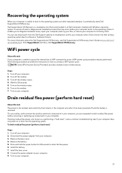
... OS Recovery User's Guide at www.dell.com/ serviceabilitytools. Steps 1. Turn off the wireless router. 4. Turn on your computer does not power on how to troubleshoot and fix your computer. 9. Drain residual flea power (perform hard reset) About this task If your computer. Disconnect the power adapter from the Dell Support website to conduct a WiFi power cycle: NOTE: Some ISPs (Internet Service Providers) provide a modem/router combo device. Press and hold the power button...
... OS Recovery User's Guide at www.dell.com/ serviceabilitytools. Steps 1. Turn off the wireless router. 4. Turn on your computer does not power on how to troubleshoot and fix your computer. 9. Drain residual flea power (perform hard reset) About this task If your computer. Disconnect the power adapter from the Dell Support website to conduct a WiFi power cycle: NOTE: Some ISPs (Internet Service Providers) provide a modem/router combo device. Press and hold the power button...


