Setup and Specifications
Page 3
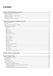
... Alienware x15 R2 6 Front...6 Right...6 Left...7 Top...7 Back...8 Bottom...9 Chapter 3: Specifications of Alienware x15 R2 10 Dimensions and weight...10 Processor...10 Chipset...10 Operating system...11 Memory...11 External ports...11 Internal slots...12 Wireless module...12 Audio...12 Storage...13 Media-card reader...13 Keyboard...14 Camera...14 Touchpad...15 Power adapter...15 Battery...16 Display...17 GPU-Integrated...18 GPU-Discrete...18 Operating and storage environment...18 Chapter 4: Keyboard shortcuts of Alienware x15 R2 19 Chapter 5: Low blue light...
... Alienware x15 R2 6 Front...6 Right...6 Left...7 Top...7 Back...8 Bottom...9 Chapter 3: Specifications of Alienware x15 R2 10 Dimensions and weight...10 Processor...10 Chipset...10 Operating system...11 Memory...11 External ports...11 Internal slots...12 Wireless module...12 Audio...12 Storage...13 Media-card reader...13 Keyboard...14 Camera...14 Touchpad...15 Power adapter...15 Battery...16 Display...17 GPU-Integrated...18 GPU-Discrete...18 Operating and storage environment...18 Chapter 4: Keyboard shortcuts of Alienware x15 R2 19 Chapter 5: Low blue light...
Setup and Specifications
Page 8
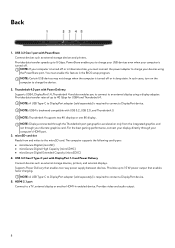
... graphics card. microSD-card slot Reads from the integrated graphics and not through your devices using a display adapter. Supports Power Delivery that enables faster charging. Thunderbolt 4.0 port with DisplayPort 1.4 and Power Delivery Connect devices such as external storage devices and printers. Back 1. USB 3.2 Gen 1 port with USB 3.2, USB 2.0, and Thunderbolt 3. Provides data transfer speeds up to a TV, external display or another HDMI-in sleep state. NOTE: Thunderbolt 4 supports two 4K displays or one 8K display. Provides video and audio output...
... graphics card. microSD-card slot Reads from the integrated graphics and not through your devices using a display adapter. Supports Power Delivery that enables faster charging. Thunderbolt 4.0 port with DisplayPort 1.4 and Power Delivery Connect devices such as external storage devices and printers. Back 1. USB 3.2 Gen 1 port with USB 3.2, USB 2.0, and Thunderbolt 3. Provides data transfer speeds up to a TV, external display or another HDMI-in sleep state. NOTE: Thunderbolt 4 supports two 4K displays or one 8K display. Provides video and audio output...
Setup and Specifications
Page 12
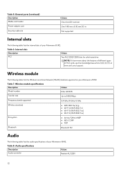
... internal slots of M.2 cards, see the knowledge base article 000144170 at www.dell.com/support. Table 5. External ports (continued) Description Media-card reader Power-adapter port Security-cable slot Values One microSD-card slot One 7.40 mm x 5.10 mm DC-in Not supported Internal slots The following table lists the audio specifications of your Alienware x15 R2. Internal slots Description M.2 Values Two M.2 2230/2280 slots for solid-state drive NOTE: To learn more about the features of different types of your Alienware x15 R2...
... internal slots of M.2 cards, see the knowledge base article 000144170 at www.dell.com/support. Table 5. External ports (continued) Description Media-card reader Power-adapter port Security-cable slot Values One microSD-card slot One 7.40 mm x 5.10 mm DC-in Not supported Internal slots The following table lists the audio specifications of your Alienware x15 R2. Internal slots Description M.2 Values Two M.2 2230/2280 slots for solid-state drive NOTE: To learn more about the features of different types of your Alienware x15 R2...
Setup and Specifications
Page 14
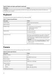
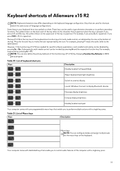
...) changing Function Key Behavior in your keyboard have two symbols on your computer. Table 11. These keys can define the primary behavior of your Alienware x15 R2. For more information, see Keyboard shortcuts. Camera specifications Description Number of your Alienware x15 R2. Table 12. Table 10. Keyboard The following table lists the camera specifications of cameras Values One Camera type HD RGB-Infrared camera Camera location Front Camera sensor type CMOS sensor technology Camera resolution: Still image 0.92 megapixel Video...
...) changing Function Key Behavior in your keyboard have two symbols on your computer. Table 11. These keys can define the primary behavior of your Alienware x15 R2. For more information, see Keyboard shortcuts. Camera specifications Description Number of your Alienware x15 R2. Table 12. Table 10. Keyboard The following table lists the camera specifications of cameras Values One Camera type HD RGB-Infrared camera Camera location Front Camera sensor type CMOS sensor technology Camera resolution: Still image 0.92 megapixel Video...
Setup and Specifications
Page 19
... typed out. The keys F1-F12 at the top row of the keyboard are needed for specific software applications, multi-media functionality can configure modes and assign multiple tasks for the macro keys on the upper part of the key is pressed. However, if the function keys F1-F12 are function keys for shortcuts remain the same across all language configurations. List of keyboard shortcuts Keys Description Disable/enable Full Speed Mode Adjust keyboard backlight brightness Switch to external display...
... typed out. The keys F1-F12 at the top row of the keyboard are needed for specific software applications, multi-media functionality can configure modes and assign multiple tasks for the macro keys on the upper part of the key is pressed. However, if the function keys F1-F12 are function keys for shortcuts remain the same across all language configurations. List of keyboard shortcuts Keys Description Disable/enable Full Speed Mode Adjust keyboard backlight brightness Switch to external display...
Setup and Specifications
Page 22
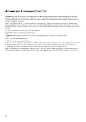
... experience. You can quickly access settings such as profiles, macros, AlienFX, and game library. Alienware Command Center Alienware Command Center (AWCC) provides a single interface to the computer or attached peripherals. It also enables you to create, assign, and share game-specific lighting maps to your computer or game. AWCC also supports Sound Management, Thermal Controls, CPU, GPU, Memory (RAM) monitoring. The AWCC dashboard displays most recently played or...
... experience. You can quickly access settings such as profiles, macros, AlienFX, and game library. Alienware Command Center Alienware Command Center (AWCC) provides a single interface to the computer or attached peripherals. It also enables you to create, assign, and share game-specific lighting maps to your computer or game. AWCC also supports Sound Management, Thermal Controls, CPU, GPU, Memory (RAM) monitoring. The AWCC dashboard displays most recently played or...
Service Manual
Page 3
... instructions...5 Electrostatic discharge-ESD protection...6 ESD field service kit ...6 After working inside your computer...7 Chapter 2: Removing and installing components 8 Recommended tools...8 Screw list...8 Major components of Alienware x15 R2...9 Disassembly and reassembly ...11 Base cover...11 Battery...15 Battery cable...17 Wireless card...19 Solid-state drive...22 Solid-state drive bracket...25 Fans...27 Rear-I/O cover...31 Power-adapter port...33 Headset port...35 Display assembly...38 Speakers...42 Touchpad...43 Keyboard-controller board...46 System board...48 Fan and...
... instructions...5 Electrostatic discharge-ESD protection...6 ESD field service kit ...6 After working inside your computer...7 Chapter 2: Removing and installing components 8 Recommended tools...8 Screw list...8 Major components of Alienware x15 R2...9 Disassembly and reassembly ...11 Base cover...11 Battery...15 Battery cable...17 Wireless card...19 Solid-state drive...22 Solid-state drive bracket...25 Fans...27 Rear-I/O cover...31 Power-adapter port...33 Headset port...35 Display assembly...38 Speakers...42 Touchpad...43 Keyboard-controller board...46 System board...48 Fan and...
Service Manual
Page 5
... keyboard, mouse, and monitor from your computer and then unplug the cable from your computer. CAUTION: Before touching anything inside your computer, ground yourself by the Dell technical assistance team. Save and close all open applications. 2. Safety instructions Use the following safety guidelines to dissipate static electricity which could harm internal components. WARNING: Before working inside the computer, replace all power sources before connecting...
... keyboard, mouse, and monitor from your computer and then unplug the cable from your computer. CAUTION: Before touching anything inside your computer, ground yourself by the Dell technical assistance team. Save and close all open applications. 2. Safety instructions Use the following safety guidelines to dissipate static electricity which could harm internal components. WARNING: Before working inside the computer, replace all power sources before connecting...
Service Manual
Page 6
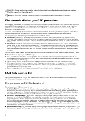
.... Never use of your skin, the ESD mat, and the hardware is a best practice to regularly test the strap prior to install the component. NOTE: The color of wireless anti-static straps is the 6 they do not remove the component from the ESD bag and placed directly on parts with a beep code emitted for lower power requirements and...
.... Never use of your skin, the ESD mat, and the hardware is a best practice to regularly test the strap prior to install the component. NOTE: The color of wireless anti-static straps is the 6 they do not remove the component from the ESD bag and placed directly on parts with a beep code emitted for lower power requirements and...
Service Manual
Page 7
... components. Replace any media cards, discs, or any hardware components ● ESD Packaging - The ESD bag should be folded over and taped shut and all attached devices to keep sensitive parts separate from sensitive parts before working on your computer and all the same foam packing material should be shipped and received in . Connect any external devices, peripherals, or cables you removed before physically...
... components. Replace any media cards, discs, or any hardware components ● ESD Packaging - The ESD bag should be folded over and taped shut and all attached devices to keep sensitive parts separate from sensitive parts before working on your computer and all the same foam packing material should be shipped and received in . Connect any external devices, peripherals, or cables you removed before physically...
Service Manual
Page 10
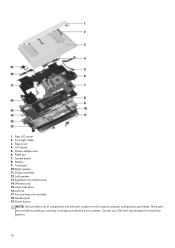
Power-adapter port 6. Keyboard-controller board 14. Left fan 17. These parts are available according to warranty coverages purchased by the customer. Contact your Dell sales representative for the original computer configuration purchased. Rear I /O board 5. Left speaker 13. Wireless card 15. solid-state drive 16. Fan and heat-sink assembly 18. Right fan 7. Touchpad 10. 1. I /O-cover 2. System board 8. Headset port 19. Battery 9. Tron-light cable 3. Base cover 4. Right speaker 11. Display assembly 12. Power button NOTE: Dell provides a list of...
Power-adapter port 6. Keyboard-controller board 14. Left fan 17. These parts are available according to warranty coverages purchased by the customer. Contact your Dell sales representative for the original computer configuration purchased. Rear I /O board 5. Left speaker 13. Wireless card 15. solid-state drive 16. Fan and heat-sink assembly 18. Right fan 7. Touchpad 10. 1. I /O-cover 2. System board 8. Headset port 19. Battery 9. Tron-light cable 3. Base cover 4. Right speaker 11. Display assembly 12. Power button NOTE: Dell provides a list of...
Service Manual
Page 16
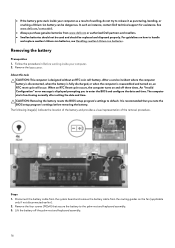
... to enter the BIOS and configure the date and time. After a service incident where the computer battery is disconnected, when the battery is fully discharged, or when the computer is displayed prompting you note the BIOS setup program's settings before removing the battery. The computer starts functioning normally after setting the date and time. Lift the battery off three times. Removing the battery Prerequisites 1. Remove the base cover. Disconnect the battery cable...
... to enter the BIOS and configure the date and time. After a service incident where the computer battery is disconnected, when the battery is fully discharged, or when the computer is displayed prompting you note the BIOS setup program's settings before removing the battery. The computer starts functioning normally after setting the date and time. Lift the battery off three times. Removing the battery Prerequisites 1. Remove the base cover. Disconnect the battery cable...
Service Manual
Page 51
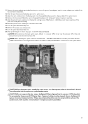
11. Open the latch and disconnect the display cable from the system board and peel the display cable off the fan and heat-sink assembly. 12. Remove the five screws (M2x4) that the M.2 2230 solid-state drive mounting bracket has been removed from the palm-rest and keyboard assembly and peel the power-adapter port cable off the system board. 14. Turn the system-board assembly over . 20.After...
11. Open the latch and disconnect the display cable from the system board and peel the display cable off the fan and heat-sink assembly. 12. Remove the five screws (M2x4) that the M.2 2230 solid-state drive mounting bracket has been removed from the palm-rest and keyboard assembly and peel the power-adapter port cable off the system board. 14. Turn the system-board assembly over . 20.After...
Service Manual
Page 64
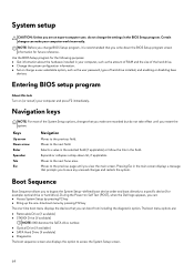
... information about the hardware installed in the main screen displays a message that you make your computer and press F2 immediately. Entering BIOS setup program About this task Turn on Self Test (POST), when the Dell logo appears, you can make are recorded but do not change a user-selectable option, such as the amount of RAM and the size of hard drive installed, and enabling or disabling base devices. System setup CAUTION: Unless...
... information about the hardware installed in the main screen displays a message that you make your computer and press F2 immediately. Entering BIOS setup program About this task Turn on Self Test (POST), when the Dell logo appears, you can make are recorded but do not change a user-selectable option, such as the amount of RAM and the size of hard drive installed, and enabling or disabling base devices. System setup CAUTION: Unless...
Service Manual
Page 65
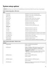
.... Default: Enabled Enables or disables the USB emulation feature. Displays the model number of keyboard installed on your computer. Displays the processor speed. Displays the processor identification code. Displays the size of AC adapter. Displays the speed of the integrated SATA hard drive controller. 65 USB emulation is off. Default: Enabled Allows you to configure the operating mode of memory. System setup options-Main menu Main System Time System Date BIOS Version Product Name Service Tag Asset Tag CPU Type CPU Speed CPU ID CPU Cache...
.... Default: Enabled Enables or disables the USB emulation feature. Displays the model number of keyboard installed on your computer. Displays the processor speed. Displays the processor identification code. Displays the size of AC adapter. Displays the speed of the integrated SATA hard drive controller. 65 USB emulation is off. Default: Enabled Allows you to configure the operating mode of memory. System setup options-Main menu Main System Time System Date BIOS Version Product Name Service Tag Asset Tag CPU Type CPU Speed CPU ID CPU Cache...
Service Manual
Page 66
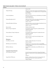
...recover BIOS without user actions. Default: 2 SupportAssist OS Recovery Enables or disables the boot flow for the Dell operating system Recovery tool. Default: Disabled 66 Default: Disabled Maintenance Data Wipe on next boot Enables or disables data wipe on the user primary hard drive or an external USB key. Set the battery charge settings with Battery Selects the timeout value for the keyboard backlight when an AC adapter is plugged into the computer. Table 4. Default: 1 minute Battery Health Battery Charge Configuration Displays the battery health. Default: Adaptive...
...recover BIOS without user actions. Default: 2 SupportAssist OS Recovery Enables or disables the boot flow for the Dell operating system Recovery tool. Default: Disabled 66 Default: Disabled Maintenance Data Wipe on next boot Enables or disables data wipe on the user primary hard drive or an external USB key. Set the battery charge settings with Battery Selects the timeout value for the keyboard backlight when an AC adapter is plugged into the computer. Table 4. Default: 1 minute Battery Health Battery Charge Configuration Displays the battery health. Default: Adaptive...
Service Manual
Page 67
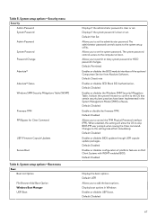
...password controls access to the system setup utility. Default: Deactivate Enables or disables SED Block SID Authentication. Default: Disabled Enables or disables the Windows SMM Security Mitigations Table. It allows the system firmware to confirm to permit or deny system password or HDD password changes. Default: Enabled Displays the boot options. Display boot options in the System Management Mode (SMM) software. Default: Enabled Allows you to skip BIOS PPI user prompts when issuing the Clear command. Default: Enabled Enables or disables configuration of the optional Computrace Service...
...password controls access to the system setup utility. Default: Deactivate Enables or disables SED Block SID Authentication. Default: Disabled Enables or disables the Windows SMM Security Mitigations Table. It allows the system firmware to confirm to permit or deny system password or HDD password changes. Default: Enabled Displays the boot options. Display boot options in the System Management Mode (SMM) software. Default: Enabled Allows you to skip BIOS PPI user prompts when issuing the Clear command. Default: Enabled Enables or disables configuration of the optional Computrace Service...

Service Manual
Page 69
... new password when prompted. In the Search support box, enter the Service Tag of your application. Select Setup Password, update, or delete the existing setup password, and press Enter or Tab. Press Esc and a message prompts you to www.dell.com/support. 2. Wait for one minute. 3. NOTE: For information on your computer. Click Product support. About this task CAUTION: Clearing CMOS settings will reset the BIOS settings on how to reset Windows...
... new password when prompted. In the Search support box, enter the Service Tag of your application. Select Setup Password, update, or delete the existing setup password, and press Enter or Tab. Press Esc and a message prompts you to www.dell.com/support. 2. Wait for one minute. 3. NOTE: For information on your computer. Click Product support. About this task CAUTION: Clearing CMOS settings will reset the BIOS settings on how to reset Windows...
Service Manual
Page 72
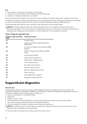
... not covered by a pause. Off: ● Power adapter is connected, and the battery is fully charged. ● Computer is running on battery, and the battery has more information, see SupportAssist Pre-Boot System Performance Check. 72 Diagnostic-light LED codes Diagnostic light codes (Red, Problem description Blue) 2,1 Processor failure 2,2 System board: BIOS or Read-Only Memory (ROM) failure 2,3 No memory or Random-Access Memory (RAM) detected 2,4 Memory or Random-Access Memory (RAM) failure 2,5 Invalid memory installed 2,6 System-board or chipset error 2,7 Display...
... not covered by a pause. Off: ● Power adapter is connected, and the battery is fully charged. ● Computer is running on battery, and the battery has more information, see SupportAssist Pre-Boot System Performance Check. 72 Diagnostic-light LED codes Diagnostic light codes (Red, Problem description Blue) 2,1 Processor failure 2,2 System board: BIOS or Read-Only Memory (ROM) failure 2,3 No memory or Random-Access Memory (RAM) detected 2,4 Memory or Random-Access Memory (RAM) failure 2,5 Invalid memory installed 2,6 System-board or chipset error 2,7 Display...
Service Manual
Page 73
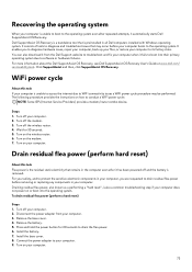
... your computer, you to diagnose hardware issues, repair your computer, back up your files, or restore your computer to your computer boots to drain the flea power. 6. For more information about the Dell SupportAssist OS Recovery, see Dell SupportAssist OS Recovery User's Guide at www.dell.com/ serviceabilitytools. Turn off your computer. 2. Connect the power adapter to its factory state. Remove the battery. 5. Recovering the operating system When your computer is...
... your computer, you to diagnose hardware issues, repair your computer, back up your files, or restore your computer to your computer boots to drain the flea power. 6. For more information about the Dell SupportAssist OS Recovery, see Dell SupportAssist OS Recovery User's Guide at www.dell.com/ serviceabilitytools. Turn off your computer. 2. Connect the power adapter to its factory state. Remove the battery. 5. Recovering the operating system When your computer is...


