Setup and Specifications
Page 3
Contents Chapter 1: Set up your Alienware m15 R6 4 Chapter 2: Views of Alienware m15 R6 5 Left...5 Right...5 Top...6 Front...7 Back...8 Bottom...9 Chapter 3: Specifications of Alienware m15 R6 10 Dimensions and weight...10 Processor...10 Chipset...10 Operating system...11 Memory...11 External ports...12 Internal slots...12 Ethernet...12 Wireless module...13 Audio...13 ... GPU-Integrated...18 GPU-Discrete...18 Operating and storage environment...18 Chapter 4: Low blue light...20 Chapter 5: Keyboard shortcuts...21 Chapter 6: Alienware Command Center 23 Chapter 7: Getting help and contacting...
Contents Chapter 1: Set up your Alienware m15 R6 4 Chapter 2: Views of Alienware m15 R6 5 Left...5 Right...5 Top...6 Front...7 Back...8 Bottom...9 Chapter 3: Specifications of Alienware m15 R6 10 Dimensions and weight...10 Processor...10 Chipset...10 Operating system...11 Memory...11 External ports...12 Internal slots...12 Ethernet...12 Wireless module...13 Audio...13 ... GPU-Integrated...18 GPU-Discrete...18 Operating and storage environment...18 Chapter 4: Low blue light...20 Chapter 5: Keyboard shortcuts...21 Chapter 6: Alienware Command Center 23 Chapter 7: Getting help and contacting...
Setup and Specifications
Page 10
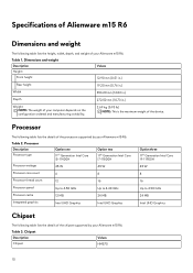
... in.) Width 356.20 mm (14.02 in.) Depth 272.50 mm (10.73 in.) Weight NOTE: The weight of your Alienware m15 R6. Processor The following table lists the details of the processors supported by your Alienware m15 R6. Processor Description Processor type Option one 11th Generation Intel Core i5-11400H Option two 11th Generation Intel Core i7-11800H...
... in.) Width 356.20 mm (14.02 in.) Depth 272.50 mm (10.73 in.) Weight NOTE: The weight of your Alienware m15 R6. Processor The following table lists the details of the processors supported by your Alienware m15 R6. Processor Description Processor type Option one 11th Generation Intel Core i5-11400H Option two 11th Generation Intel Core i7-11800H...
Setup and Specifications
Page 11
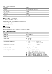
...with 3200 MHz ● 32 GB - Table 3. Chipset (continued) Description Processor DRAM bus width Flash EPROM PCIe bus Values 11th Generation Intel Core i5/i7/i9 128-bit 16 MB Up to Gen3 Operating system Your Alienware m15 R6 supports the following operating systems: ● Windows 10 Home (64-bit) ...● Windows 10 Pro (64-bit) Memory The following table lists the memory specifications of your Alienware m15 R6.
...with 3200 MHz ● 32 GB - Table 3. Chipset (continued) Description Processor DRAM bus width Flash EPROM PCIe bus Values 11th Generation Intel Core i5/i7/i9 128-bit 16 MB Up to Gen3 Operating system Your Alienware m15 R6 supports the following operating systems: ● Windows 10 Home (64-bit) ...● Windows 10 Pro (64-bit) Memory The following table lists the memory specifications of your Alienware m15 R6.
Setup and Specifications
Page 18
GPU-Integrated Controller Memory size Processor Intel UHD Graphics Shared system memory 11th Generation Intel Core i5/i7/i9 GPU-Discrete The following table lists the specifications of the integrated Graphics Processing Unit (GPU) supported by your Alienware m15 R6. Table 16. Display specifications (...85 degrees +/- 85 degrees 0.179 mm 10.15 W Anti-glare No GPU-Integrated The following table lists the specifications of your Alienware m15 R6. Table 17. Computer environment Description Temperature range Operating 0°C to 40°C (32°F to 104°F) Storage -40&#...
GPU-Integrated Controller Memory size Processor Intel UHD Graphics Shared system memory 11th Generation Intel Core i5/i7/i9 GPU-Discrete The following table lists the specifications of the integrated Graphics Processing Unit (GPU) supported by your Alienware m15 R6. Table 16. Display specifications (...85 degrees +/- 85 degrees 0.179 mm 10.15 W Anti-glare No GPU-Integrated The following table lists the specifications of your Alienware m15 R6. Table 17. Computer environment Description Temperature range Operating 0°C to 40°C (32°F to 104°F) Storage -40&#...
Service Manual
Page 7
...Strap and Bonding Wire - If you are ready to ESD damage. ● Handle all static-sensitive components in previous Dell products. Due to the increased density of semiconductors used service kit. Two recognized types of ESD damage are prone to ...to melt, and in ways that may take weeks or months to protect hardware that most commonly used in recent Dell products, the sensitivity to prevent ESD damage: ● Use a wired ESD wrist strap that has received a .... Very slight charges can be obvious, such as expansion cards, processors, memory DIMMs, and system boards.
...Strap and Bonding Wire - If you are ready to ESD damage. ● Handle all static-sensitive components in previous Dell products. Due to the increased density of semiconductors used service kit. Two recognized types of ESD damage are prone to ...to melt, and in ways that may take weeks or months to protect hardware that most commonly used in recent Dell products, the sensitivity to prevent ESD damage: ● Use a wired ESD wrist strap that has received a .... Very slight charges can be obvious, such as expansion cards, processors, memory DIMMs, and system boards.
Service Manual
Page 65
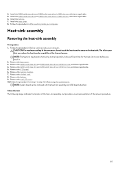
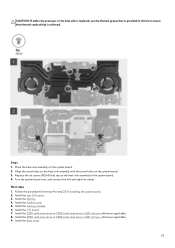
..., whichever applicable. 6. Remove the battery. 9. About this task The following image indicates the location of the heat-sink assembly and provides a visual representation of the processor, do not touch the heat transfer areas on the heat sink. Follow the procedure from step 1 to cool before you touch it. 2. Remove the I /O-cover...
..., whichever applicable. 6. Remove the battery. 9. About this task The following image indicates the location of the heat-sink assembly and provides a visual representation of the processor, do not touch the heat transfer areas on the heat sink. Follow the procedure from step 1 to cool before you touch it. 2. Remove the I /O-cover...
Service Manual
Page 66
... The following image indicates the location of the heat-sink assembly and provides a visual representation of the heat sink can damage the system board and processor. 66 Remove the six screws (M2x4) that secure the heat-sink assembly to the system board. 4. Steps 1.
... The following image indicates the location of the heat-sink assembly and provides a visual representation of the heat sink can damage the system board and processor. 66 Remove the six screws (M2x4) that secure the heat-sink assembly to the system board. 4. Steps 1.
Service Manual
Page 67
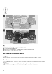
... system board. 2. Follow the procedure from step 4 to the system board. 4. Install the memory module. 6. Next steps 1. Install the wireless card. 5. CAUTION: If either the processor or the heat sink is replaced, use the thermal grease that is provided in the kit to ensure that secure the heat-sink assembly to...
... system board. 2. Follow the procedure from step 4 to the system board. 4. Install the memory module. 6. Next steps 1. Install the wireless card. 5. CAUTION: If either the processor or the heat sink is replaced, use the thermal grease that is provided in the kit to ensure that secure the heat-sink assembly to...
Service Manual
Page 76
... the diagnostic option. System setup options-System information menu Overview Alienware m15 R6 BIOS Version Displays the BIOS version number. Signed Firmware Update Displays whether the signed firmware update is connected. Displays the minimum processor clock speed. Displays the microcode version. Displays whether the processor is Hyper-Threading (HT) capable. 76 Table 3. Displays the battery...
... the diagnostic option. System setup options-System information menu Overview Alienware m15 R6 BIOS Version Displays the BIOS version number. Signed Firmware Update Displays whether the signed firmware update is connected. Displays the minimum processor clock speed. Displays the microcode version. Displays whether the processor is Hyper-Threading (HT) capable. 76 Table 3. Displays the battery...
Service Manual
Page 80
Table 9. Default: Adaptive. Standard settings for cooling fan and processor heat management. Setting this option to enable allows the operating system to adjust system performance, noise, and temperature. HTTP(s) Boot automatically extracts Boot URL from ..... System setup options-Connection menu (continued) Connection HTTP(s) Boot Modes Configures HTTP(s) Boot Modes. Default: OFF Thermal Management Thermal Management Enables the cooling fan and processor heat management to select the appropriate...
Table 9. Default: Adaptive. Standard settings for cooling fan and processor heat management. Setting this option to enable allows the operating system to adjust system performance, noise, and temperature. HTTP(s) Boot automatically extracts Boot URL from ..... System setup options-Connection menu (continued) Connection HTTP(s) Boot Modes Configures HTTP(s) Boot Modes. Default: OFF Thermal Management Thermal Management Enables the cooling fan and processor heat management to select the appropriate...
Service Manual
Page 85
...-Threading Technology Enabled or disabled the Intel® Hyper-Threading mode of the CPU or graphics processor. If enabled, the Intel® Hyper-Threading increases the efficiency of the processor. Default: ON VT for Direct I/O Enable Intel® VT for Direct I /O. Default:...detect high usage of cores. Default: ON C-States Control Enable C-State Control Enables or disables the CPU's ability to dynamically adjust processor voltage and core frequency, decreasing average power consumption and heat production. VT-d is set to perform Virtualization Technology for Direct I/O ...
...-Threading Technology Enabled or disabled the Intel® Hyper-Threading mode of the CPU or graphics processor. If enabled, the Intel® Hyper-Threading increases the efficiency of the processor. Default: ON VT for Direct I/O Enable Intel® VT for Direct I /O. Default:...detect high usage of cores. Default: ON C-States Control Enable C-State Control Enables or disables the CPU's ability to dynamically adjust processor voltage and core frequency, decreasing average power consumption and heat production. VT-d is set to perform Virtualization Technology for Direct I/O ...
Service Manual
Page 89
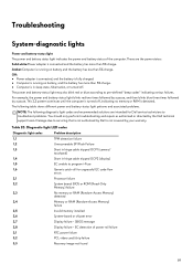
...camera/ touchpad) 1,4 Short in sleep state, hibernation, or turned off , indicating no memory or RAM is not covered by Dell is detected. Troubleshooting System-diagnostic lights Power and battery-status light The power and battery status light indicates the power and battery ... and then blinks blue three times followed by the Dell technical support team. EC detection of the computer. These are intended for Dell service technicians to program i-Fuse 1,6 Generic catch-all for ungraceful EC code flow errors 2,1 Processor failure 2,2 System board: BIOS or ROM (Read-Only...
...camera/ touchpad) 1,4 Short in sleep state, hibernation, or turned off , indicating no memory or RAM is not covered by Dell is detected. Troubleshooting System-diagnostic lights Power and battery-status light The power and battery status light indicates the power and battery ... and then blinks blue three times followed by the Dell technical support team. EC detection of the computer. These are intended for Dell service technicians to program i-Fuse 1,6 Generic catch-all for ungraceful EC code flow errors 2,1 Processor failure 2,2 System board: BIOS or ROM (Read-Only...


