Setup and Specifications
Page 3
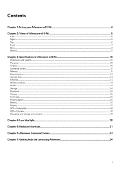
... Alienware m15 R6 4 Chapter 2: Views of Alienware m15 R6 5 Left...5 Right...5 Top...6 Front...7 Back...8 Bottom...9 Chapter 3: Specifications of Alienware m15 R6 10 Dimensions and weight...10 Processor...10 Chipset...10 Operating system...11 Memory...11 External ports...12 Internal slots...12 Ethernet...12 Wireless module...13 Audio...13 Storage...14 Keyboard...14 Camera...15 Touchpad...15 Power adapter...16 Battery...16 Display...17 GPU-Integrated...18 GPU-Discrete...18 Operating and storage environment...18 Chapter 4: Low blue light...
... Alienware m15 R6 4 Chapter 2: Views of Alienware m15 R6 5 Left...5 Right...5 Top...6 Front...7 Back...8 Bottom...9 Chapter 3: Specifications of Alienware m15 R6 10 Dimensions and weight...10 Processor...10 Chipset...10 Operating system...11 Memory...11 External ports...12 Internal slots...12 Ethernet...12 Wireless module...13 Audio...13 Storage...14 Keyboard...14 Camera...15 Touchpad...15 Power adapter...16 Battery...16 Display...17 GPU-Integrated...18 GPU-Discrete...18 Operating and storage environment...18 Chapter 4: Low blue light...

Setup and Specifications
Page 12
...-cable slot Not supported Internal slots The following table lists the wired Ethernet Local Area Network (LAN) specifications of your Alienware m15 R6. Ethernet specifications Description Model number Values Ethernet controller integrated to this port. Table 5. External ports Description Network port Values One RJ-45 port USB ports ● Two USB 3.2 Gen 1 ports ● One USB 3.2 Gen 1 port with PowerShare ● One Thunderbolt 4 port with Power Delivery or one USB 3.2 Gen 2 Type-C port with DisplayPort NOTE: You can connect a Dell Docking Station to the system board...
...-cable slot Not supported Internal slots The following table lists the wired Ethernet Local Area Network (LAN) specifications of your Alienware m15 R6. Ethernet specifications Description Model number Values Ethernet controller integrated to this port. Table 5. External ports Description Network port Values One RJ-45 port USB ports ● Two USB 3.2 Gen 1 ports ● One USB 3.2 Gen 1 port with PowerShare ● One Thunderbolt 4 port with Power Delivery or one USB 3.2 Gen 2 Type-C port with DisplayPort NOTE: You can connect a Dell Docking Station to the system board...
Setup and Specifications
Page 21
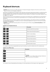
... language configuration. These keys can be disabled by changing Function Key Behavior in BIOS setup program. The keys F1-F12 at the bottom of the key. However, if the function keys F1-F12 are function keys for specific software applications, multi-media functionality can be invoked by pressing fn and the respective function key. List of keyboard shortcuts Keys Description Disable/enable Performance Boost Adjust keyboard backlight brightness Switch to external display Disable/enable Bluetooth Decrease display brightness Increase display brightness Disable/enable touchpad...
... language configuration. These keys can be disabled by changing Function Key Behavior in BIOS setup program. The keys F1-F12 at the bottom of the key. However, if the function keys F1-F12 are function keys for specific software applications, multi-media functionality can be invoked by pressing fn and the respective function key. List of keyboard shortcuts Keys Description Disable/enable Performance Boost Adjust keyboard backlight brightness Switch to external display Disable/enable Bluetooth Decrease display brightness Increase display brightness Disable/enable touchpad...
Setup and Specifications
Page 23
... supports Sound Management, Thermal Controls, CPU, GPU, Memory (RAM) monitoring. AWCC embeds Peripheral Controls to ensure a unified experience and the ability to link these settings to your own individual lighting effects and apply them to create your computer or game. AWCC supports the following features: ● FX: Create and manage the AlienFX zones. ● Fusion: Includes the ability to adjust game-specific Power Management, Sound Management, and Thermal Management features. ● Peripheral Management: Enables...
... supports Sound Management, Thermal Controls, CPU, GPU, Memory (RAM) monitoring. AWCC embeds Peripheral Controls to ensure a unified experience and the ability to link these settings to your own individual lighting effects and apply them to create your computer or game. AWCC supports the following features: ● FX: Create and manage the AlienFX zones. ● Fusion: Includes the ability to adjust game-specific Power Management, Sound Management, and Thermal Management features. ● Peripheral Management: Enables...
Service Manual
Page 3
... instructions...6 Electrostatic discharge-ESD protection...7 ESD field service kit ...7 Transporting sensitive components...8 After working inside your computer...8 Chapter 2: Removing and installing components 9 Recommended tools...9 Screw list...9 Major components of Alienware m15 R6 ...10 Base cover...12 Removing the base cover...12 Installing the base cover...15 Battery...18 Battery cable...18 Removing the battery...20 Installing the battery...21 Battery cable...22 Lithium-ion battery precautions...22 Removing the battery cable...23 Installing the battery cable...23 Solid-state drive...
... instructions...6 Electrostatic discharge-ESD protection...7 ESD field service kit ...7 Transporting sensitive components...8 After working inside your computer...8 Chapter 2: Removing and installing components 9 Recommended tools...9 Screw list...9 Major components of Alienware m15 R6 ...10 Base cover...12 Removing the base cover...12 Installing the base cover...15 Battery...18 Battery cable...18 Removing the battery...20 Installing the battery...21 Battery cable...22 Lithium-ion battery precautions...22 Removing the battery cable...23 Installing the battery cable...23 Solid-state drive...
Service Manual
Page 4
... Removing the palm-rest and keyboard assembly...72 Installing the palm-rest and keyboard assembly...73 Chapter 3: Drivers and downloads...74 Chapter 4: System setup...75 BIOS overview...75 Entering BIOS setup program...75 Navigation keys...75 Boot Sequence...75 System setup options...76 System and setup password...86 Assigning a system setup password...86 Deleting or changing an existing system setup password 87 Clearing CMOS settings...87 Clearing BIOS (System Setup) and System passwords 87 Chapter 5: Troubleshooting...89 System-diagnostic lights...89 Flashing BIOS (USB key...
... Removing the palm-rest and keyboard assembly...72 Installing the palm-rest and keyboard assembly...73 Chapter 3: Drivers and downloads...74 Chapter 4: System setup...75 BIOS overview...75 Entering BIOS setup program...75 Navigation keys...75 Boot Sequence...75 System setup options...76 System and setup password...86 Assigning a system setup password...86 Deleting or changing an existing system setup password 87 Clearing CMOS settings...87 Clearing BIOS (System Setup) and System passwords 87 Chapter 5: Troubleshooting...89 System-diagnostic lights...89 Flashing BIOS (USB key...
Service Manual
Page 6
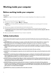
.... Remove any installed card from the media-card reader. 6 WARNING: Disconnect your computer from all attached network devices and peripherals, such as keyboard, mouse, and monitor from your computer and then unplug the cable from the network device. 5. CAUTION: To avoid damaging the computer, ensure that the ports and the connectors are using a different operating system, see the Regulatory Compliance home page at www.dell.com/regulatory_compliance. When connecting cables...
.... Remove any installed card from the media-card reader. 6 WARNING: Disconnect your computer from all attached network devices and peripherals, such as keyboard, mouse, and monitor from your computer and then unplug the cable from the network device. 5. CAUTION: To avoid damaging the computer, ensure that the ports and the connectors are using a different operating system, see the Regulatory Compliance home page at www.dell.com/regulatory_compliance. When connecting cables...
Service Manual
Page 8
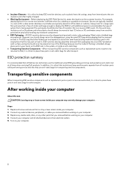
... highly charged. ● Working Environment - Replace any media cards, discs, or any hardware components ● ESD Packaging - Turn on top of the bag is free of clutter and large enough to deploy the ESD kit with additional space to place these parts in . Before deploying the ESD Field Service kit, assess the situation at all times when servicing Dell products. On the work area...
... highly charged. ● Working Environment - Replace any media cards, discs, or any hardware components ● ESD Packaging - Turn on top of the bag is free of clutter and large enough to deploy the ESD kit with additional space to place these parts in . Before deploying the ESD Field Service kit, assess the situation at all times when servicing Dell products. On the work area...
Service Manual
Page 57
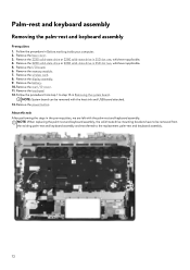
... system board. Remove the memory module. 7. Replace the screw (M2x2) that you can reconnect the cables correctly after you have made to secure the cable. 5. Connect the keyboard-controller board cable to the keyboard-controller board and close the latch to secure the cable. 6. Install the battery. 2. Remove the base cover. 3. Remove the battery. 4. Connect the keyboard cable to the keyboard-controller board and close the latch to the BIOS using the BIOS setup program. Install the base cover. 3. Steps 1. Connect the keyboard-backlight cable to the keyboard-controller board...
... system board. Remove the memory module. 7. Replace the screw (M2x2) that you can reconnect the cables correctly after you have made to secure the cable. 5. Connect the keyboard-controller board cable to the keyboard-controller board and close the latch to secure the cable. 6. Install the battery. 2. Remove the base cover. 3. Remove the battery. 4. Connect the keyboard cable to the keyboard-controller board and close the latch to the BIOS using the BIOS setup program. Install the base cover. 3. Steps 1. Connect the keyboard-backlight cable to the keyboard-controller board...
Service Manual
Page 72
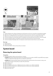
... SSD slot two, whichever applicable. 5. Remove the 2230 solid-state drive or 2280 solid-state drive in Before working inside your computer. 2. Remove the power button. Remove the I /O-cover. 11. Remove the wireless card. 8. NOTE: System board can be removed from step 1 to be removed with the palm-rest and keyboard assembly. Remove the memory module. 7. Remove the 2230 solid-state drive or 2280 solid-state drive in Removing the system board. NOTE: When replacing the...
... SSD slot two, whichever applicable. 5. Remove the 2230 solid-state drive or 2280 solid-state drive in Before working inside your computer. 2. Remove the power button. Remove the I /O-cover. 11. Remove the wireless card. 8. NOTE: System board can be removed from step 1 to be removed with the palm-rest and keyboard assembly. Remove the memory module. 7. Remove the 2230 solid-state drive or 2280 solid-state drive in Removing the system board. NOTE: When replacing the...
Service Manual
Page 75
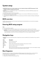
... the user password, type of hard drive installed, and enabling or disabling base devices. Moves to the next focus area. Pressing Esc in the main screen displays a message that the keyboard is lost. NOTE: The F2 prompt indicates that prompts you to a specific device (for it is displayed, watch for example: optical drive or hard drive). If you must watch for future reference. Then, turn off your computer work incorrectly. Entering BIOS setup program...
... the user password, type of hard drive installed, and enabling or disabling base devices. Moves to the next focus area. Pressing Esc in the main screen displays a message that the keyboard is lost. NOTE: The F2 prompt indicates that prompts you to a specific device (for it is displayed, watch for example: optical drive or hard drive). If you must watch for future reference. Then, turn off your computer work incorrectly. Entering BIOS setup program...
Service Manual
Page 77
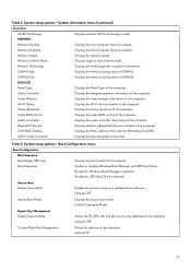
.... Enables or disables Windows Boot Manager and UEFI Hard Drive. MEMORY Memory Installed Displays the total computer memory installed. Memory Technology Displays the technology that is used for selection of the LAN on Motherboard (LOM). Video Memory Displays the video memory information of the computer. Video BIOS Version Displays the video BIOS version of the computer. DIMM A Size Displays the memory configuration of DIMM B. DIMM B Size Displays the memory configuration of DIMM A. Audio Controller Displays the audio controller information of the computer. Bluetooth...
.... Enables or disables Windows Boot Manager and UEFI Hard Drive. MEMORY Memory Installed Displays the total computer memory installed. Memory Technology Displays the technology that is used for selection of the LAN on Motherboard (LOM). Video Memory Displays the video memory information of the computer. Video BIOS Version Displays the video BIOS version of the computer. DIMM A Size Displays the memory configuration of DIMM B. DIMM B Size Displays the memory configuration of DIMM A. Audio Controller Displays the audio controller information of the computer. Bluetooth...
Service Manual
Page 78
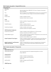
...8482; adapter to be used during pre-boot. Default: ON Enable Microphone Enables or disables microphone. Enable Internal Speaker Enables or disables internal speaker. By default, Enable External USB Ports is selected. By default, Enable USB Boot Support is selected. Enable Thunderbolt™ Boot Support Enables or disables Thunderbolt™ adapter peripheral devices and USB devices connected to the Thunderbolt™ adapter to run the PCIe device's UEFI Option ROM(s) during BIO's pre-boot. Changes to the date take effect immediately. Audio Enable Audio Enables or...
...8482; adapter to be used during pre-boot. Default: ON Enable Microphone Enables or disables microphone. Enable Internal Speaker Enables or disables internal speaker. By default, Enable External USB Ports is selected. By default, Enable USB Boot Support is selected. Enable Thunderbolt™ Boot Support Enables or disables Thunderbolt™ adapter peripheral devices and USB devices connected to the Thunderbolt™ adapter to run the PCIe device's UEFI Option ROM(s) during BIO's pre-boot. Changes to the date take effect immediately. Audio Enable Audio Enables or...
Service Manual
Page 79
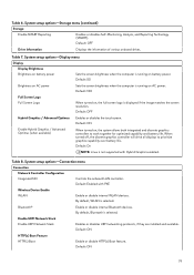
...capability and battery life. Table 8. Default: Enabled with Hybrid Graphics enabled. Bluetooth® Enable or disable internal Bluetooth devices. Default: ON 79 Default: ON HTTP(s) Boot Feature HTTP(s) Boot Enable or disable HTTP(s) Boot feature. Default: OFF Drive Information Displays the information of various onboard drives. By default, Bluetooth is not supported with PXE Wireless Device Enable WLAN Enable or disable internal WLAN devices. System setup options-Display menu Display Display Brightness Brightness on battery power Sets the screen brightness when the...
...capability and battery life. Table 8. Default: Enabled with Hybrid Graphics enabled. Bluetooth® Enable or disable internal Bluetooth devices. Default: ON 79 Default: ON HTTP(s) Boot Feature HTTP(s) Boot Enable or disable HTTP(s) Boot feature. Default: OFF Drive Information Displays the information of various onboard drives. By default, Bluetooth is not supported with PXE Wireless Device Enable WLAN Enable or disable internal WLAN devices. System setup options-Display menu Display Display Brightness Brightness on battery power Sets the screen brightness when the...
Service Manual
Page 81
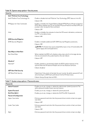
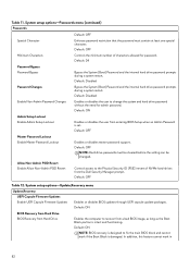
... Enables you to set ) when booting to enter the admin password (if set , change, or delete the M.2 PCIe SSD-0 password. Data Wipe on Next Boot Start Data Wipe When enabled, the BIOS will schedule a data wipe cycle for Clear Commands Enables or disables the Trusted Platform Model (TPM) Physical Presence Interface (PPI). Enables you to set , change , or delete the administrator (admin) password. Table 10. System setup options-Passwords menu Passwords Admin Password System Password M.2 PCIe SSD-0 Password Configuration...
... Enables you to set ) when booting to enter the admin password (if set , change, or delete the M.2 PCIe SSD-0 password. Data Wipe on Next Boot Start Data Wipe When enabled, the BIOS will schedule a data wipe cycle for Clear Commands Enables or disables the Trusted Platform Model (TPM) Physical Presence Interface (PPI). Enables you to set , change , or delete the administrator (admin) password. Table 10. System setup options-Passwords menu Passwords Admin Password System Password M.2 PCIe SSD-0 Password Configuration...
Service Manual
Page 82
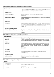
...: BIOS recovery is designed to recover from a bad BIOS image, as long as the Boot Block portion is damaged. Default: OFF Minimum Characters Controls the minimum number of NVMe hard-drives from entering BIOS Setup when an Admin Password is set. Default: ON Admin Setup Lockout Enable Admin Setup Lockout Enables or disables the user from the Dell Security Manager prompt. In addition, this feature cannot work if the Boot Block is intact and functioning. Default: Disabled Enable Non-Admin Password Changes Enables...
...: BIOS recovery is designed to recover from a bad BIOS image, as long as the Boot Block portion is damaged. Default: OFF Minimum Characters Controls the minimum number of NVMe hard-drives from entering BIOS Setup when an Admin Password is set. Default: ON Admin Setup Lockout Enable Admin Setup Lockout Enables or disables the user from the Dell Security Manager prompt. In addition, this feature cannot work if the Boot Block is intact and functioning. Default: Disabled Enable Non-Admin Password Changes Enables...
Service Manual
Page 83
... AC Enables or disables basic checks when AC power is not installed. Creates a system Asset Tag that can be changed. System setup options-Keyboard menu Keyboard Fn Lock Options Fn Lock Options Enables or disables the Fn lock mode. Default: ON Lock Mode Controls operation of EC corruption, ME corruption, or a hardware issue. Default: ON SupportAssist OS Recovery Enables or disables the boot flow for SupportAssist OS Recovery tool, in BIOS, the Asset Tag cannot be used by Dell Auto OS Recovery Threshold, and local Service...
... AC Enables or disables basic checks when AC power is not installed. Creates a system Asset Tag that can be changed. System setup options-Keyboard menu Keyboard Fn Lock Options Fn Lock Options Enables or disables the Fn lock mode. Default: ON Lock Mode Controls operation of EC corruption, ME corruption, or a hardware issue. Default: ON SupportAssist OS Recovery Enables or disables the boot flow for SupportAssist OS Recovery tool, in BIOS, the Asset Tag cannot be used by Dell Auto OS Recovery Threshold, and local Service...
Service Manual
Page 87
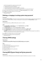
... board. 6. You cannot delete or change the System and/or Setup password, re enter the new password when prompted. Select Setup Password, alter or delete the existing setup password and press Enter or Tab. Press Y to save the changes. Remove the base cover. 2. Press the power button for one minute. 5. Type the system password that the Password Status is Locked. About this task CAUTION: Clearing CMOS settings will reset the BIOS settings on or reboot. The System Security screen...
... board. 6. You cannot delete or change the System and/or Setup password, re enter the new password when prompted. Select Setup Password, alter or delete the existing setup password and press Enter or Tab. Press Y to save the changes. Remove the base cover. 2. Press the power button for one minute. 5. Type the system password that the Password Status is Locked. About this task CAUTION: Clearing CMOS settings will reset the BIOS settings on or reboot. The System Security screen...
Service Manual
Page 89
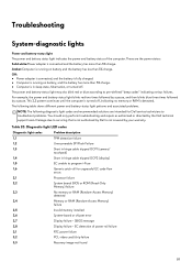
...2,2 System board: BIOS or ROM (Read-Only Memory) failure 2,3 No memory or RAM (Random-Access Memory) detected 2,4 Memory or RAM (Random-Access Memory) failure 2,5 Invalid memory installed 2,6 System-board or chipset error 2,7 Display failure - Diagnostic-light LED codes Diagnostic light codes Problem description 1,1 TPM detection failure 1,2 Unrecoverable SPI Flash Failure 1,3 Short in hinge cable tripped OCP1 (camera/ touchpad) 1,4 Short in sleep state, hibernation, or turned off , indicating no memory or RAM is in hinge cable tripped OCP2 (display) 1,5 EC...
...2,2 System board: BIOS or ROM (Read-Only Memory) failure 2,3 No memory or RAM (Random-Access Memory) detected 2,4 Memory or RAM (Random-Access Memory) failure 2,5 Invalid memory installed 2,6 System-board or chipset error 2,7 Display failure - Diagnostic-light LED codes Diagnostic light codes Problem description 1,1 TPM detection failure 1,2 Unrecoverable SPI Flash Failure 1,3 Short in hinge cable tripped OCP1 (camera/ touchpad) 1,4 Short in sleep state, hibernation, or turned off , indicating no memory or RAM is in hinge cable tripped OCP2 (display) 1,5 EC...
Service Manual
Page 90
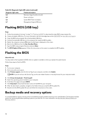
... Product support, enter the Service Tag of the BIOS for your computer. 6. For more information. Copy the BIOS setup program file to www.dell.com/support. 3. Go to the bootable USB drive. 4. Click Drivers & downloads > Find it myself. 5. Click Download to flash (update) the BIOS when an update is recommended to create a recovery drive to troubleshoot and fix problems that needs the BIOS update. 5. After the download is displayed on the screen. Select the operating system installed on your computer. 8. Diagnostic-light LED codes...
... Product support, enter the Service Tag of the BIOS for your computer. 6. For more information. Copy the BIOS setup program file to www.dell.com/support. 3. Go to the bootable USB drive. 4. Click Drivers & downloads > Find it myself. 5. Click Download to flash (update) the BIOS when an update is recommended to create a recovery drive to troubleshoot and fix problems that needs the BIOS update. 5. After the download is displayed on the screen. Select the operating system installed on your computer. 8. Diagnostic-light LED codes...


