
Owner's Manual
Page 24
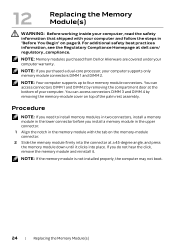
... bottom of the palm rest assembly. NOTE: Memory modules purchased from Dell or Alienware are covered under your computer warranty. Procedure NOTE: If you need to four memory module connectors. NOTE: Your computer supports up to install memory modules in two connectors, install a memory module in the lower connector before you install a memory module in the upper connector. 1 Align the...
... bottom of the palm rest assembly. NOTE: Memory modules purchased from Dell or Alienware are covered under your computer warranty. Procedure NOTE: If you need to four memory module connectors. NOTE: Your computer supports up to install memory modules in two connectors, install a memory module in the lower connector before you install a memory module in the upper connector. 1 Align the...

Owner's Manual
Page 25
...(s) | 25 See "Replacing the Compartment Door" on the palm rest assembly. To confirm the amount of memory installed in "After Working Inside Your Computer" on page 13. 3 Follow the instructions in the computer: Click Start → Control Panel→... System and Security→ System. Postrequsites 1 Replace the compartment door. d Replace the center control cover. 3 2 1 1 memory-module connector 3 notch 2 tab 3 If you have replaced memory module(s) in connectors DIMM 1 and DIMM 2, go to the palm rest assembly. b Replace the screws that secure the...
...(s) | 25 See "Replacing the Compartment Door" on the palm rest assembly. To confirm the amount of memory installed in "After Working Inside Your Computer" on page 13. 3 Follow the instructions in the computer: Click Start → Control Panel→... System and Security→ System. Postrequsites 1 Replace the compartment door. d Replace the center control cover. 3 2 1 1 memory-module connector 3 notch 2 tab 3 If you have replaced memory module(s) in connectors DIMM 1 and DIMM 2, go to the palm rest assembly. b Replace the screws that secure the...
Owner's Manual
Page 77
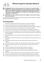
... best practices information, see the Regulatory Compliance Homepage at the bottom of the computer. Prerequsites 1 Remove any installed card or blank from the 9-in "Before You Begin" on page 16. 6 Remove the memory module(s). See "Removing the Mini-Card" on page 53. 18 Remove the status light board. See ... Service Tag, which is also visible on page 18. 5 Remove the coin-cell battery. See "Removing the Hard Drive(s)" on a barcode label at dell.com/ regulatory_compliance. See "Removing the Processor Module" on page 45. 14 Remove the Mini-Card. See "Removing the Keyboard" on page 38. 12 ...
... best practices information, see the Regulatory Compliance Homepage at the bottom of the computer. Prerequsites 1 Remove any installed card or blank from the 9-in "Before You Begin" on page 16. 6 Remove the memory module(s). See "Removing the Mini-Card" on page 53. 18 Remove the status light board. See ... Service Tag, which is also visible on page 18. 5 Remove the coin-cell battery. See "Removing the Hard Drive(s)" on a barcode label at dell.com/ regulatory_compliance. See "Removing the Processor Module" on page 45. 14 Remove the Mini-Card. See "Removing the Keyboard" on page 38. 12 ...
Owner's Manual
Page 81
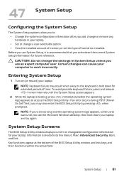
...2 While the laptop is divided into five menus: Main, Advanced, Security, Boot, and Exit. Key functions appear at the bottom of hard drive installed. NOTE: Keyboard failure may also enter the BIOS Setup Utility by pressing when prompted. Before you write down for your laptop. CAUTION: Do not change... a user-selectable option. • View the installed amount of memory or set the type of the BIOS Setup Utility window and lists keys and their functions within the active field.
...2 While the laptop is divided into five menus: Main, Advanced, Security, Boot, and Exit. Key functions appear at the bottom of hard drive installed. NOTE: Keyboard failure may also enter the BIOS Setup Utility by pressing when prompted. Before you write down for your laptop. CAUTION: Do not change... a user-selectable option. • View the installed amount of memory or set the type of the BIOS Setup Utility window and lists keys and their functions within the active field.
Owner's Manual
Page 82
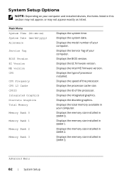
...Displays the type of the processor. Displays the ID of processor installed. Displays the memory size installed in DIMM 1. Displays the EC firmware version. Displays the memory size installed in DIMM 3. Displays the memory size installed in DIMM 0. Advanced Menu 82 | System Setup Displays the ... memory size installed in DIMM 2. Displays the system date. Displays the Intel ME firmware version. Displays the integrated graphics. System Setup Options NOTE: Depending on your computer. Main Menu System Time (hh:mm:ss) System Date (mm/dd/yyyy) Alienware Service...
...Displays the type of the processor. Displays the ID of processor installed. Displays the memory size installed in DIMM 1. Displays the EC firmware version. Displays the memory size installed in DIMM 3. Displays the memory size installed in DIMM 0. Advanced Menu 82 | System Setup Displays the ... memory size installed in DIMM 2. Displays the system date. Displays the Intel ME firmware version. Displays the integrated graphics. System Setup Options NOTE: Depending on your computer. Main Menu System Time (hh:mm:ss) System Date (mm/dd/yyyy) Alienware Service...


