Owner's Manual
Page 4
10 Replacing the Hard Drive(s 21 Procedure 21 Postrequsites 21 11 Removing the Memory Module(s) . . . . 22 Prerequsites 22 Procedure 22 12 Replacing the Memory Module(s) . . . . 24 Procedure 24 Postrequsites 25 13 Removing the Graphics-Card Heat Sink Fan 26 Prerequsites 26 Procedure 27 14 Replacing the Graphics-Card Heat Sink Fan 28 Procedure 28 Postrequsites 28 15 Removing the Processor Heat-Sink Fan 29 Prerequsites 29 Procedure 30...
10 Replacing the Hard Drive(s 21 Procedure 21 Postrequsites 21 11 Removing the Memory Module(s) . . . . 22 Prerequsites 22 Procedure 22 12 Replacing the Memory Module(s) . . . . 24 Procedure 24 Postrequsites 25 13 Removing the Graphics-Card Heat Sink Fan 26 Prerequsites 26 Procedure 27 14 Replacing the Graphics-Card Heat Sink Fan 28 Procedure 28 Postrequsites 28 15 Removing the Processor Heat-Sink Fan 29 Prerequsites 29 Procedure 30...
Owner's Manual
Page 5
... 35 Procedure 36 20 Replacing the Processor Heat-Sink 37 Procedure 37 Postrequsites 37 21 Removing the Processor Module 38 Prerequsites 38 Procedure 38 22 Replacing the Processor Module . . . . . 40 Procedure 40 Postrequsites 40 23 Removing the Center Control Cover 41 Prerequsites 41 Procedure 41 24 Replacing the Center Control Cover 44 Procedure 44 Postrequsites 44 25 Removing the Keyboard 45 Prerequsites 45...
... 35 Procedure 36 20 Replacing the Processor Heat-Sink 37 Procedure 37 Postrequsites 37 21 Removing the Processor Module 38 Prerequsites 38 Procedure 38 22 Replacing the Processor Module . . . . . 40 Procedure 40 Postrequsites 40 23 Removing the Center Control Cover 41 Prerequsites 41 Procedure 41 24 Replacing the Center Control Cover 44 Procedure 44 Postrequsites 44 25 Removing the Keyboard 45 Prerequsites 45...

Owner's Manual
Page 9
... Instructions Use the following safety guidelines to protect your computer from their edges and avoid touching pins and contacts. After you finish working inside the computer, replace all covers, panels, and screws before opening the computer cover or panels. NOTE: If you are using a different operating system, see the Regulatory Compliance Homepage at dell.com/regulatory_compliance. 1 Before You Begin Turn Off Your Computer and Connected Devices...
... Instructions Use the following safety guidelines to protect your computer from their edges and avoid touching pins and contacts. After you finish working inside the computer, replace all covers, panels, and screws before opening the computer cover or panels. NOTE: If you are using a different operating system, see the Regulatory Compliance Homepage at dell.com/regulatory_compliance. 1 Before You Begin Turn Off Your Computer and Connected Devices...

Owner's Manual
Page 10
...service technician is authorized to remove the computer cover and access any of the computer. Some cables have connectors with locking tabs or thumb-screws that the connectors and ports are correctly oriented and aligned. See the safety instructions for complete information about safety precautions, working inside your computer, ground yourself by touching... When connecting cables, ensure that you disconnect a cable, pull on its connector or on its pull-tab, not on the cable itself. Recommended Tools The procedures in -1 Media Card Reader. CAUTION: Before touching anything inside...
...service technician is authorized to remove the computer cover and access any of the computer. Some cables have connectors with locking tabs or thumb-screws that the connectors and ports are correctly oriented and aligned. See the safety instructions for complete information about safety precautions, working inside your computer, ground yourself by touching... When connecting cables, ensure that you disconnect a cable, pull on its connector or on its pull-tab, not on the cable itself. Recommended Tools The procedures in -1 Media Card Reader. CAUTION: Before touching anything inside...
Owner's Manual
Page 11
... their electrical outlets CAUTION: Before turning on your computer, replace all attached devices to do so may damage your computer and all screws and ensure that no stray screws remain inside your computer • Connect any external devices, cables, cards, and any other part(s) you removed before working on your computer • Connect your computer. 2 After Working Inside Your Computer After you complete...
... their electrical outlets CAUTION: Before turning on your computer, replace all attached devices to do so may damage your computer and all screws and ensure that no stray screws remain inside your computer • Connect any external devices, cables, cards, and any other part(s) you removed before working on your computer • Connect your computer. 2 After Working Inside Your Computer After you complete...
Owner's Manual
Page 21
... the instructions in "After Working Inside Your Computer" on the system board and press the hard drive until it is fully seated. 6 Tighten the captive screws that secure the hard-drive assembly to install an operating system, drivers, and utilities on page 15. 2 Replace the battery pack. For additional safety best practices information, see the Regulatory Compliance Homepage at dell.com/ regulatory_compliance. Postrequsites 1 Replace the...
... the instructions in "After Working Inside Your Computer" on the system board and press the hard drive until it is fully seated. 6 Tighten the captive screws that secure the hard-drive assembly to install an operating system, drivers, and utilities on page 15. 2 Replace the battery pack. For additional safety best practices information, see the Regulatory Compliance Homepage at dell.com/ regulatory_compliance. Postrequsites 1 Replace the...
Owner's Manual
Page 22
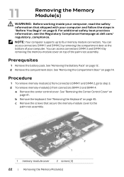
... supports up to step 3. 2 To remove memory-module(s) from connectors DIMM 3 and DIMM 4: a Remove the center control cover. See "Removing the Keyboard" on page 14. See "Removing the Center Control Cover" on page 12. 2 Remove the compartment door. You can access connectors DIMM 1 and DIMM 2 by removing the memory-module cover on page 9. Procedure 1 To remove memory module(s) from connectors DIMM 1 and DIMM 2, go to four memory module connectors. Prerequsites 1 Remove the battery pack. See "Removing...
... supports up to step 3. 2 To remove memory-module(s) from connectors DIMM 3 and DIMM 4: a Remove the center control cover. See "Removing the Keyboard" on page 14. See "Removing the Center Control Cover" on page 12. 2 Remove the compartment door. You can access connectors DIMM 1 and DIMM 2 by removing the memory-module cover on page 9. Procedure 1 To remove memory module(s) from connectors DIMM 1 and DIMM 2, go to four memory module connectors. Prerequsites 1 Remove the battery pack. See "Removing...
Owner's Manual
Page 24
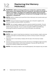
..., your computer supports only memory module connectors DIMM 1 and DIMM 2. For additional safety best practices information, see the Regulatory Compliance Homepage at a 45-degree angle, and press the memory module down until it . You can access connectors DIMM 1 and DIMM 2 by removing the memory-module cover on the memory-module connector. 2 Slide the memory module firmly into place. 12 Replacing the Memory Module(s) WARNING: Before working inside your...
..., your computer supports only memory module connectors DIMM 1 and DIMM 2. For additional safety best practices information, see the Regulatory Compliance Homepage at a 45-degree angle, and press the memory module down until it . You can access connectors DIMM 1 and DIMM 2 by removing the memory-module cover on the memory-module connector. 2 Slide the memory module firmly into place. 12 Replacing the Memory Module(s) WARNING: Before working inside your...
Owner's Manual
Page 38
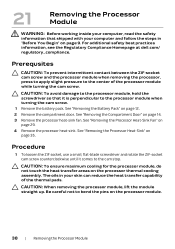
...-sink fan. Procedure 1 To loosen the ZIF socket, use a small, flat-blade screwdriver and rotate the ZIF-socket cam screw counterclockwise until it is perpendicular to the processor module when turning the cam screw. 1 Remove the battery pack. For additional safety best practices information, see the Regulatory Compliance Homepage at dell.com/ regulatory_compliance. CAUTION: When removing the processor module...
...-sink fan. Procedure 1 To loosen the ZIF socket, use a small, flat-blade screwdriver and rotate the ZIF-socket cam screw counterclockwise until it is perpendicular to the processor module when turning the cam screw. 1 Remove the battery pack. For additional safety best practices information, see the Regulatory Compliance Homepage at dell.com/ regulatory_compliance. CAUTION: When removing the processor module...
Owner's Manual
Page 44
... shipped with the slots on page 15. 2 Replace the battery pack. Procedure 1 Connect the media control keys cable to the connector on the system board. 2 Align the tabs on the center control cover with your computer, read the safety information that secure the center control cover to the computer base. See "Replacing the Battery Pack" on page 9. 24 Replacing the Center Control Cover WARNING: Before working inside your computer...
... shipped with the slots on page 15. 2 Replace the battery pack. Procedure 1 Connect the media control keys cable to the connector on the system board. 2 Align the tabs on the center control cover with your computer, read the safety information that secure the center control cover to the computer base. See "Replacing the Battery Pack" on page 9. 24 Replacing the Center Control Cover WARNING: Before working inside your computer...
Owner's Manual
Page 51
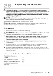
...-Card slot for the Mini-Card supported by your computer and follow the steps in "Before You Begin" on the system board. 3 Press the other than Dell or Alienware. NOTE: Depending on the Mini-Card WLAN (2 or 3 antenna cables) Main WLAN (white triangle) Auxiliary WLAN (black triangle) MIMO WLAN (gray triangle) (optional) Antenna Cable Color Scheme white black gray Replacing the Mini-Card | 51 Procedure 1 Remove...
...-Card slot for the Mini-Card supported by your computer and follow the steps in "Before You Begin" on the system board. 3 Press the other than Dell or Alienware. NOTE: Depending on the Mini-Card WLAN (2 or 3 antenna cables) Main WLAN (white triangle) Auxiliary WLAN (black triangle) MIMO WLAN (gray triangle) (optional) Antenna Cable Color Scheme white black gray Replacing the Mini-Card | 51 Procedure 1 Remove...
Owner's Manual
Page 54
Procedure 1 Remove the new wirelessHD card from its packaging. See "Replacing the Keyboard" on page 15. 4 Replace the battery pack. See "Replacing the Compartment Door" on page 48. 2 Replace the center control cover. 30 Replacing the WirelessHD Card WARNING: Before working inside your computer, read the safety information that secures the wirelessHD card to the system board. 4 Connect the wirelessHD card cable to the connector on the wirelessHD card. If you...
Procedure 1 Remove the new wirelessHD card from its packaging. See "Replacing the Keyboard" on page 15. 4 Replace the battery pack. See "Replacing the Compartment Door" on page 48. 2 Replace the center control cover. 30 Replacing the WirelessHD Card WARNING: Before working inside your computer, read the safety information that secures the wirelessHD card to the system board. 4 Connect the wirelessHD card cable to the connector on the wirelessHD card. If you...
Owner's Manual
Page 66
.... 3 Connect the touch pad cable, LVDS cable, and Media Card Reader cable to the computer base. 7 Replace the compartment door. See "Replacing the Status Light Board" on page 11. 66 | Replacing the Palm Rest Assembly See "Replacing the Battery Pack" on page 13. 9 Replace any cards or blank that secure the palm rest assembly to the connectors on the system board. Postrequsites 1 Replace the status light board. See "Replacing the Power Button Board" on page 15. 8 Replace...
.... 3 Connect the touch pad cable, LVDS cable, and Media Card Reader cable to the computer base. 7 Replace the compartment door. See "Replacing the Status Light Board" on page 11. 66 | Replacing the Palm Rest Assembly See "Replacing the Battery Pack" on page 13. 9 Replace any cards or blank that secure the palm rest assembly to the connectors on the system board. Postrequsites 1 Replace the status light board. See "Replacing the Power Button Board" on page 15. 8 Replace...
Owner's Manual
Page 77
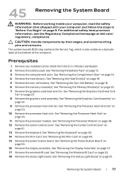
... -1 Media Card Reader. 2 Remove the battery pack. For additional safety best practices information, see the Regulatory Compliance Homepage at the bottom of the computer. See "Removing the Processor Module" on page 57. 17 Remove the wirelessHD card. See "Removing the Center Control Cover" on page 14. 4 Remove the hard drive(s). See "Removing the Compartment Door" on page 41. 13 Remove the keyboard. See "Removing the Power Button Board" on a barcode label at dell...
... -1 Media Card Reader. 2 Remove the battery pack. For additional safety best practices information, see the Regulatory Compliance Homepage at the bottom of the computer. See "Removing the Processor Module" on page 57. 17 Remove the wirelessHD card. See "Removing the Center Control Cover" on page 14. 4 Remove the hard drive(s). See "Removing the Compartment Door" on page 41. 13 Remove the keyboard. See "Removing the Power Button Board" on a barcode label at dell...
Owner's Manual
Page 80
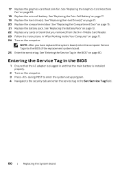
... board, enter the computer Service Tag into the BIOS of the replacement system board. 25 Enter the service tag. See "Replacing the Coin-Cell Battery" on page 28. 18 Replace the coin-cell battery. See "Replacing the Hard Drive(s)" on page 15. 21 Replace the battery pack. See "Replacing the Compartment Door" on page 21. 20 Replace the compartment door. NOTE: After you removed from the 9-in-1 Media Card Reader. 23 Follow the instructions...
... board, enter the computer Service Tag into the BIOS of the replacement system board. 25 Enter the service tag. See "Replacing the Coin-Cell Battery" on page 28. 18 Replace the coin-cell battery. See "Replacing the Hard Drive(s)" on page 15. 21 Replace the battery pack. See "Replacing the Compartment Door" on page 21. 20 Replace the compartment door. NOTE: After you removed from the 9-in-1 Media Card Reader. 23 Follow the instructions...
Owner's Manual
Page 81
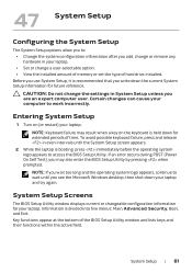
... you wait too long and the operating system logo appears, continue to work incorrectly. Certain changes can cause your laptop. System Setup | 81 47 System Setup Configuring the System Setup The System Setup options allow you to access the BIOS Setup Utility. CAUTION: Do not change a user-selectable option. • View the installed amount of memory or set the type of hard drive installed. Entering System Setup 1 Turn on the keyboard is recommended that you write down for...
... you wait too long and the operating system logo appears, continue to work incorrectly. Certain changes can cause your laptop. System Setup | 81 47 System Setup Configuring the System Setup The System Setup options allow you to access the BIOS Setup Utility. CAUTION: Do not change a user-selectable option. • View the installed amount of memory or set the type of hard drive installed. Entering System Setup 1 Turn on the keyboard is recommended that you write down for...
Owner's Manual
Page 83
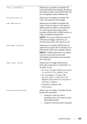
... battery life. Intel SpeedStep Virtualization USB Emulation USB Wake Support USB Power Share Integrated Network Allows you to charge USB devices when the computer is turned off . Allows you to the operating system. • Enabled: Internal LAN is off or in the absence of USB device (floppy, hard drive, or memory key) when this feature may not wake the computer. Disabling this option is enabled. System Setup | 83 Allows you to enable or disable the onboard LAN controller. • Disabled: Internal LAN...
... battery life. Intel SpeedStep Virtualization USB Emulation USB Wake Support USB Power Share Integrated Network Allows you to charge USB devices when the computer is turned off . Allows you to the operating system. • Enabled: Internal LAN is off or in the absence of USB device (floppy, hard drive, or memory key) when this feature may not wake the computer. Disabling this option is enabled. System Setup | 83 Allows you to enable or disable the onboard LAN controller. • Disabled: Internal LAN...
Owner's Manual
Page 84
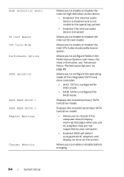
... you use AC adapters that are not supported by your computer. • Enabled: BIOS will detect unsupported AC adapters and display an error on page 85. High Definition Audio SD Card Reader CPU Turbo Mode Performance Options SATA Operation SATA HARD DRIVE 1 SATA HARD DRIVE 2 Adapter Warnings Charger Behavior Allows you to enable or disable the internal high definition audio device. • Disabled: The internal audio device is disabled and is not visible to enable or disable battery charging. 84 | System Setup Displays the installed primary SATA hard drive model.
... you use AC adapters that are not supported by your computer. • Enabled: BIOS will detect unsupported AC adapters and display an error on page 85. High Definition Audio SD Card Reader CPU Turbo Mode Performance Options SATA Operation SATA HARD DRIVE 1 SATA HARD DRIVE 2 Adapter Warnings Charger Behavior Allows you to enable or disable the internal high definition audio device. • Disabled: The internal audio device is disabled and is not visible to enable or disable battery charging. 84 | System Setup Displays the installed primary SATA hard drive model.
Owner's Manual
Page 87
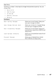
... System Setup and save your changes to CMOS. Boot Menu Use the up- or down- Exit Discarding Changes Allows you to exit System Setup and load previous values from : • Hard Drive • USB Storage • CD/DVD/BD • Removal Devices • Network Exit Menu Exit Saving Changes Allows you to exit System Setup and save your changes to CMOS. arrow keys to load default values for all Setup items. System Setup | 87...
... System Setup and save your changes to CMOS. Boot Menu Use the up- or down- Exit Discarding Changes Allows you to exit System Setup and load previous values from : • Hard Drive • USB Storage • CD/DVD/BD • Removal Devices • Network Exit Menu Exit Saving Changes Allows you to exit System Setup and save your changes to CMOS. arrow keys to load default values for all Setup items. System Setup | 87...
Owner's Manual
Page 88
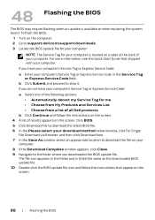
... click Download Now. 7 In the Save As window, select an appropriate location to download the file on the screen. To flash the BIOS: 1 Turn on the computer. 2 Go to support.dell.com/support/downloads. 3 Locate the BIOS update file for your computer: NOTE: The Service Tag for me • Choose from My Products and Services List • Choose from a list of all Dell products b Click Continue and follow the instructions that...
... click Download Now. 7 In the Save As window, select an appropriate location to download the file on the screen. To flash the BIOS: 1 Turn on the computer. 2 Go to support.dell.com/support/downloads. 3 Locate the BIOS update file for your computer: NOTE: The Service Tag for me • Choose from My Products and Services List • Choose from a list of all Dell products b Click Continue and follow the instructions that...


