
Mobile Manual
Page 5
CONTENTS CHAPTER 1: SETTING UP YOUR LAPTOP 9 Before Setting Up Your Laptop 10 Connect the AC Adapter 12 Press the Power Button 13 Connect the Network Cable (Optional 14 Set Up Microsoft Windows 15 Set Up WirelessHD (Optional 16 Set Up Wireless Display (Optional 17 Connect to the Internet (Optional 18 CHAPTER 2: GETTING TO KNOW YOUR LAPTOP 21 Left View Features 22 Right View Features 25 Back View Features 27 Display Features 28 Computer Base and Keyboard Features 30 Status Lights 32 Media Control Keys 33 3
CONTENTS CHAPTER 1: SETTING UP YOUR LAPTOP 9 Before Setting Up Your Laptop 10 Connect the AC Adapter 12 Press the Power Button 13 Connect the Network Cable (Optional 14 Set Up Microsoft Windows 15 Set Up WirelessHD (Optional 16 Set Up Wireless Display (Optional 17 Connect to the Internet (Optional 18 CHAPTER 2: GETTING TO KNOW YOUR LAPTOP 21 Left View Features 22 Right View Features 25 Back View Features 27 Display Features 28 Computer Base and Keyboard Features 30 Status Lights 32 Media Control Keys 33 3
Mobile Manual
Page 12
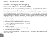
...or a Phillips head screwdriver for any missing components or damaged items to check for include: •• Laptop and AC adapter with power cable and video cable (if ordered) •• Keyboard (if ordered) •• Mouse (if ordered) •• Multimedia speakers and sub-...of the laptop •• Monitor with power cable •• Microsoft CD-key located at the bottom of receiving a shipment will not be sure to you. Report any physical damage that were shipped to inspect all safety and setup instructions before connecting your Alienware M17x!
...or a Phillips head screwdriver for any missing components or damaged items to check for include: •• Laptop and AC adapter with power cable and video cable (if ordered) •• Keyboard (if ordered) •• Mouse (if ordered) •• Multimedia speakers and sub-...of the laptop •• Monitor with power cable •• Microsoft CD-key located at the bottom of receiving a shipment will not be sure to you. Report any physical damage that were shipped to inspect all safety and setup instructions before connecting your Alienware M17x!

Mobile Manual
Page 13
...may arise as needed to answer questions in the future, or aid you explore your laptop is both level and stable. •• The power and other object. •• Nothing obstructs airflow in front of the documentation and may be easily accessed. 11 If your new laptop's ...capabilities. or any kind on a surface that adequate ventilation is provided. The media included with your Alienware laptop is designed to provide answers to many of any other cable connectors are not jammed between the laptop and a wall - Do not place the laptop in a humid location or...
...may arise as needed to answer questions in the future, or aid you explore your laptop is both level and stable. •• The power and other object. •• Nothing obstructs airflow in front of the documentation and may be easily accessed. 11 If your new laptop's ...capabilities. or any kind on a surface that adequate ventilation is provided. The media included with your Alienware laptop is designed to provide answers to many of any other cable connectors are not jammed between the laptop and a wall - Do not place the laptop in a humid location or...

Mobile Manual
Page 14
Using an incompatible cable or improperly connecting the cable to a power strip or electrical outlet may cause fire or equipment damage. 12 CHAPTER 1: SETTING UP YOUR LAPTOP Connect the AC Adapter WARNING: The AC adapter works with electrical outlets worldwide. However, power connectors and power strips vary among countries.
Using an incompatible cable or improperly connecting the cable to a power strip or electrical outlet may cause fire or equipment damage. 12 CHAPTER 1: SETTING UP YOUR LAPTOP Connect the AC Adapter WARNING: The AC adapter works with electrical outlets worldwide. However, power connectors and power strips vary among countries.

Mobile Manual
Page 26
...or inputs signal for digital audio output. NOTE: Use the S/PDIF adapter that shipped with audio programs. 9 Headphone connectors (2) - Connects to connect a TOSLINK optical cable. 8 Microphone connector - Connects to amplifiers, speakers, or TVs for use with your computer and USB devices. 7 Audio-out/Headphone/S/PDIF connector - CHAPTER 2: ...GETTING TO KNOW YOUR LAPTOP 6 USB 3.0 connectors (2) - Can also be used to connect to a pair of headphones or to a pair of headphones, powered speakers, or sound system. Connect to a powered speaker or sound system. 24
...or inputs signal for digital audio output. NOTE: Use the S/PDIF adapter that shipped with audio programs. 9 Headphone connectors (2) - Connects to connect a TOSLINK optical cable. 8 Microphone connector - Connects to amplifiers, speakers, or TVs for use with your computer and USB devices. 7 Audio-out/Headphone/S/PDIF connector - CHAPTER 2: ...GETTING TO KNOW YOUR LAPTOP 6 USB 3.0 connectors (2) - Can also be used to connect to a pair of headphones or to a pair of headphones, powered speakers, or sound system. Connect to a powered speaker or sound system. 24

Mobile Manual
Page 44
... and mini-DisplayPort-to the VGA, mini-DisplayPort, or HDMI connector on your Alienware laptop. 4. If necessary, connect one end of the power cable to a grounded three-prong power strip or wall outlet. 7. Connect one end of the display cable to -DVI adapters at www.dell.com. 1. Turn off the display and disconnect it from the...
... and mini-DisplayPort-to the VGA, mini-DisplayPort, or HDMI connector on your Alienware laptop. 4. If necessary, connect one end of the power cable to a grounded three-prong power strip or wall outlet. 7. Connect one end of the display cable to -DVI adapters at www.dell.com. 1. Turn off the display and disconnect it from the...

Mobile Manual
Page 73
...Remove the battery from the battery bay (for more information, see "Turning Off Your Computer" on page 72). 7. Press the power button to prevent the computer cover from their electrical outlets. Disconnect all attached devices from being scratched. 2. CHAPTER 4: INSTALLING AND REPLACING... to the system board, you must remove the battery from the network device. 3. CAUTION: To disconnect a network cable, first unplug the cable from your computer and then unplug the cable from the battery bay before you service the laptop. 6. Turn off your computer and all telephone or network...
...Remove the battery from the battery bay (for more information, see "Turning Off Your Computer" on page 72). 7. Press the power button to prevent the computer cover from their electrical outlets. Disconnect all attached devices from being scratched. 2. CHAPTER 4: INSTALLING AND REPLACING... to the system board, you must remove the battery from the network device. 3. CAUTION: To disconnect a network cable, first unplug the cable from your computer and then unplug the cable from the battery bay before you service the laptop. 6. Turn off your computer and all telephone or network...

Mobile Manual
Page 88
... "External Only" display. •• Use only the AC adapter that your computer is actually working electrical outlet? The power status light will be off. •• Brightness: Check and adjust the brightness of the display by pressing the...seconds. If connected to a working . •• Connections: Check all the cables to ensure that there are no loose connections anywhere. •• Power Savings: Ensure that shipped with your AC adapter cable securely connected to a power strip, ensure that the strip is not in standby mode; CHAPTER 5: TROUBLESHOOTING Basic...
... "External Only" display. •• Use only the AC adapter that your computer is actually working electrical outlet? The power status light will be off. •• Brightness: Check and adjust the brightness of the display by pressing the...seconds. If connected to a working . •• Connections: Check all the cables to ensure that there are no loose connections anywhere. •• Power Savings: Ensure that shipped with your AC adapter cable securely connected to a power strip, ensure that the strip is not in standby mode; CHAPTER 5: TROUBLESHOOTING Basic...

Mobile Manual
Page 90
Ensure that the power outlet is working , ensure that the AC adapter cable is turned on (if applicable). •• If your...8226; If an error message appears on ) are not working . •• Ensure the UPS or power strip is properly connected between your computer. Things to check: •• Ensure that all connections are ...secure. •• If any peripherals from your computer and a grounded, three-prong power outlet. CHAPTER 5: TROUBLESHOOTING When troubleshooting your peripheral devices (for example keyboard, mouse, printer, and so on ...
Ensure that the power outlet is working , ensure that the AC adapter cable is turned on (if applicable). •• If your...8226; If an error message appears on ) are not working . •• Ensure the UPS or power strip is properly connected between your computer. Things to check: •• Ensure that all connections are ...secure. •• If any peripherals from your computer and a grounded, three-prong power outlet. CHAPTER 5: TROUBLESHOOTING When troubleshooting your peripheral devices (for example keyboard, mouse, printer, and so on ...

Mobile Manual
Page 99
... for further assistance. •• If the problem persists, contact Alienware support (see "CONTACTING ALIENWARE" on page 123). 97 CHAPTER 5: TROUBLESHOOTING Power When you press the power button, the computer does not turn on •• If the AC adapter cable is connected to a surge protector or UPS, ensure that the surge protector or UPS...
... for further assistance. •• If the problem persists, contact Alienware support (see "CONTACTING ALIENWARE" on page 123). 97 CHAPTER 5: TROUBLESHOOTING Power When you press the power button, the computer does not turn on •• If the AC adapter cable is connected to a surge protector or UPS, ensure that the surge protector or UPS...

Mobile Manual
Page 123
... to rest on the power cable. •• Do not spill anything on the portion of ESD damage: •• Turn off your computer. •• To avoid electrical shock, always disconnect all cables away from where people ... walk or trip over them to the computer's case to remove peripheral cards for any other cables from the wall outlets before starting to work. •• Ground yourself by static electricity... have to prevent ESD damage. APPENDIX Computer Use •• Route the power cable and all power, modem and any reason, place them on or into your computer...
... to rest on the power cable. •• Do not spill anything on the portion of ESD damage: •• Turn off your computer. •• To avoid electrical shock, always disconnect all cables away from where people ... walk or trip over them to the computer's case to remove peripheral cards for any other cables from the wall outlets before starting to work. •• Ground yourself by static electricity... have to prevent ESD damage. APPENDIX Computer Use •• Route the power cable and all power, modem and any reason, place them on or into your computer...
Mobile Manual
Page 124
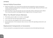
Your computer protects itself against most irregularities in the power source. Replacement Components or Accessories It is only advised to use replacement parts or accessories recommended by the warranty. •• Electrical Shock: ...General Safety Precautions •• Mechanical Shock: Your computer should never be subjected to worry about. When You Should Contact Alienware •• The battery, power cable or connector is not covered by Alienware. 122 Mechanical Shock is damaged. •• Your computer has had liquid spilled into it. •• Your ...
Your computer protects itself against most irregularities in the power source. Replacement Components or Accessories It is only advised to use replacement parts or accessories recommended by the warranty. •• Electrical Shock: ...General Safety Precautions •• Mechanical Shock: Your computer should never be subjected to worry about. When You Should Contact Alienware •• The battery, power cable or connector is not covered by Alienware. 122 Mechanical Shock is damaged. •• Your computer has had liquid spilled into it. •• Your ...

Service Manual (English Only)
Page 67
...remove the main battery (see "Removing the Keyboard" on page 55). 6 Disconnect the power button board cable from the connector on the system board. 7 Remove the two screws that is not authorized by Dell is not covered by periodically touching an unpainted metal surface (such as a connector on... your computer). Removing the Power Button Board 1 Follow the instructions in "Before You Begin" on page...
...remove the main battery (see "Removing the Keyboard" on page 55). 6 Disconnect the power button board cable from the connector on the system board. 7 Remove the two screws that is not authorized by Dell is not covered by periodically touching an unpainted metal surface (such as a connector on... your computer). Removing the Power Button Board 1 Follow the instructions in "Before You Begin" on page...

Service Manual (English Only)
Page 68
... board with the alignment posts on the chassis and secure the power button board in place. 3 Replace the two screws that secure the power button board to the palm rest assembly. 4 Connect the power button board cable to the connector on the system board. 5 Replace the keyboard (see "Replacing the Keyboard" on page 57...
... board with the alignment posts on the chassis and secure the power button board in place. 3 Replace the two screws that secure the power button board to the palm rest assembly. 4 Connect the power button board cable to the connector on the system board. 5 Replace the keyboard (see "Replacing the Keyboard" on page 57...

Service Manual (English Only)
Page 80
..."Removing the Center Control Cover" on page 49). 7 Remove the keyboard (see "Removing the Keyboard" on page 55). 8 Remove the power button board (see "Removing the Power Button Board" on page 67). 9 Remove the display assembly (see "Removing the Display Assembly" on page 71). 10 Remove the status ...light board (see "Removing the Status Light Board" on page 75). 11 Disconnect the touch pad cable, LVDS cable, and Media Card Reader cable from the ...
..."Removing the Center Control Cover" on page 49). 7 Remove the keyboard (see "Removing the Keyboard" on page 55). 8 Remove the power button board (see "Removing the Power Button Board" on page 67). 9 Remove the display assembly (see "Removing the Display Assembly" on page 71). 10 Remove the status ...light board (see "Removing the Status Light Board" on page 75). 11 Disconnect the touch pad cable, LVDS cable, and Media Card Reader cable from the ...

Service Manual (English Only)
Page 82
...turning on page 14). 13 Replace any cards or blank that no stray screws remain inside the computer. 4 Connect the touch pad cable, LVDS cable, and Media Card Reader cable to the connectors on the system board. 5 Replace the status light board (see "Replacing the Status Light Board" on page ...76). 6 Replace the display assembly (see "Replacing the Display Assembly" on page 73). 7 Replace the power button board (see "Replacing the Power Button Board" on...
...turning on page 14). 13 Replace any cards or blank that no stray screws remain inside the computer. 4 Connect the touch pad cable, LVDS cable, and Media Card Reader cable to the connectors on the system board. 5 Replace the status light board (see "Replacing the Status Light Board" on page ...76). 6 Replace the display assembly (see "Replacing the Display Assembly" on page 73). 7 Replace the power button board (see "Replacing the Power Button Board" on...

Service Manual (English Only)
Page 89
... "Replacing the Status Light Board" on page 76). 8 Replace the display assembly (see "Replacing the Display Assembly" on page 73). 9 Replace the power button board (see "Replacing the Power Button Board" on page 68). 10 Replace the keyboard (see "Replacing the Keyboard" on page 57). 11 Replace the center control cover (see... pack (see "Replacing the Battery Pack" on the computer, replace all screws and ensure that no stray screws remain inside the computer. 5 Connect the speakers cable to the computer. Speakers 89
... "Replacing the Status Light Board" on page 76). 8 Replace the display assembly (see "Replacing the Display Assembly" on page 73). 9 Replace the power button board (see "Replacing the Power Button Board" on page 68). 10 Replace the keyboard (see "Replacing the Keyboard" on page 57). 11 Replace the center control cover (see... pack (see "Replacing the Battery Pack" on the computer, replace all screws and ensure that no stray screws remain inside the computer. 5 Connect the speakers cable to the computer. Speakers 89

Service Manual (English Only)
Page 94
... the slot on the optical-drive bracket with the alignment posts on computer chassis and secure the optical-drive assembly in damage to secure the cable. 7 Replace the speakers (see "Replacing the Speakers" on page 88). 8 Replace the palm rest assembly (see "Replacing the Palm Rest Assembly" on page 81).... Light Board" on page 76). 10 Replace the display assembly (see "Replacing the Display Assembly" on page 73). 11 Replace the power button board (see "Replacing the Power Button Board" on page 68). 12 Replace the keyboard (see "Replacing the Keyboard" on page 57). 13 Replace the center control ...
... the slot on the optical-drive bracket with the alignment posts on computer chassis and secure the optical-drive assembly in damage to secure the cable. 7 Replace the speakers (see "Replacing the Speakers" on page 88). 8 Replace the palm rest assembly (see "Replacing the Palm Rest Assembly" on page 81).... Light Board" on page 76). 10 Replace the display assembly (see "Replacing the Display Assembly" on page 73). 11 Replace the power button board (see "Replacing the Power Button Board" on page 68). 12 Replace the keyboard (see "Replacing the Keyboard" on page 57). 13 Replace the center control ...


