

Comprehensive Specifications
Page 4
...8482; i7 Intel Core i5 L2 cache 256 KB L3 cache up to 8 MB Bus clock 133 MHz System chipset Mobile Intel PM55 Processor and System Chipset SDRAM bus width one or two 64-bit channels of your laptop will vary depending on computers with 9-cell battery (... DDR3 memory up to Back) Width Depth Weight with an Intel Core i7 processor. 4 GB, 6 GB, and 8 GB 4 COMPREHENSIVE SPECIFICATIONS Computer Model Alienware M17x-R2 Dimensions Height (Front to 1333 MHz Processor address bus width 32 bits Processor data width 64 bits BIOS EPROM 16 Mbit Graphics bus PCIe x16 bus supporting...
...8482; i7 Intel Core i5 L2 cache 256 KB L3 cache up to 8 MB Bus clock 133 MHz System chipset Mobile Intel PM55 Processor and System Chipset SDRAM bus width one or two 64-bit channels of your laptop will vary depending on computers with 9-cell battery (... DDR3 memory up to Back) Width Depth Weight with an Intel Core i7 processor. 4 GB, 6 GB, and 8 GB 4 COMPREHENSIVE SPECIFICATIONS Computer Model Alienware M17x-R2 Dimensions Height (Front to 1333 MHz Processor address bus width 32 bits Processor data width 64 bits BIOS EPROM 16 Mbit Graphics bus PCIe x16 bus supporting...

Comprehensive Specifications
Page 7
... 60°C (-4° to 140°F) CR-2032 AC Adapter NOTE: The 150 W AC adapter supports computers with a single graphics card and a non-Extreme Edition processor. Other configurations require the 240 W AC adapter.
... 60°C (-4° to 140°F) CR-2032 AC Adapter NOTE: The 150 W AC adapter supports computers with a single graphics card and a non-Extreme Edition processor. Other configurations require the 240 W AC adapter.
Mobile Manual
Page 26
... some time acquiring a basic understanding of the battery. Using the Wireless Control The wireless control allows you to quickly turn on your computer by adapting processor speed to your activity and by your computer over its function through the Microsoft Windows operating system. When you need to activate its lifetime. •...
... some time acquiring a basic understanding of the battery. Using the Wireless Control The wireless control allows you to quickly turn on your computer by adapting processor speed to your activity and by your computer over its function through the Microsoft Windows operating system. When you need to activate its lifetime. •...
Mobile Manual
Page 27
...higher power usage. • Switch to the Stealth mode to build a library of system management, optimization, and customization tools. As Alienware releases new programs, they download directly into and out of the control, see "Computer Base and Keyboard Features" on your selection. The.... The control will illuminate temporarily to full brightness until the function is deactivated. Alienware Command Center The Alienware® Command Center gives you can take to reduce the processor and graphics utilization and thereby reduces the energy consumption and noise level of power ...
...higher power usage. • Switch to the Stealth mode to build a library of system management, optimization, and customization tools. As Alienware releases new programs, they download directly into and out of the control, see "Computer Base and Keyboard Features" on your selection. The.... The control will illuminate temporarily to full brightness until the function is deactivated. Alienware Command Center The Alienware® Command Center gives you can take to reduce the processor and graphics utilization and thereby reduces the energy consumption and noise level of power ...

Mobile Manual
Page 29
...processor. Displays the memory size installed in memory bank 0. Allows you to enable or disable the internal Bluetooth device. • Disabled: The internal Bluetooth device is disabled and is not visible to the operating system. • Enabled: The internal Bluetooth device is enabled. Main Menu System Time System Date Alienware... Service Tag BIOS Version EC Version CPU CPU Speed CPU Cache CPU ID Displays the system time. Displays the model number of your computer. Displays the BIOS revision. Displays the speed of processor... the processor cache ... processor....
...processor. Displays the memory size installed in memory bank 0. Allows you to enable or disable the internal Bluetooth device. • Disabled: The internal Bluetooth device is disabled and is not visible to the operating system. • Enabled: The internal Bluetooth device is enabled. Main Menu System Time System Date Alienware... Service Tag BIOS Version EC Version CPU CPU Speed CPU Cache CPU ID Displays the system time. Displays the model number of your computer. Displays the BIOS revision. Displays the speed of processor... the processor cache ... processor....

Mobile Manual
Page 31
... • Enabled: The system password is enabled. • Not Enabled: The system password is disabled. Displays the status of the processor. DDR3 Voltage Allows you to enable or disable the Phoenix FailSafe™ security software to enter the memory voltage. Allows you to protect...manage your laptop and your digital files if your laptop is lost or stolen. CPU Frequency OverClocking Allows you to configure the processor over-clocking frequency. The system password controls access to the computer at boot. Memory Frequency Memory Channel Mode Displays the frequency ...
... • Enabled: The system password is enabled. • Not Enabled: The system password is disabled. Displays the status of the processor. DDR3 Voltage Allows you to enable or disable the Phoenix FailSafe™ security software to enter the memory voltage. Allows you to protect...manage your laptop and your digital files if your laptop is lost or stolen. CPU Frequency OverClocking Allows you to configure the processor over-clocking frequency. The system password controls access to the computer at boot. Memory Frequency Memory Channel Mode Displays the frequency ...
Mobile Manual
Page 35
... laptop. 6. Turn off your computer and all telephone or network cables from the battery bay (see the Regulatory Compliance Homepage at www.dell.com/regulatory_compliance. Disconnect your computer (see "Turning Off Your Computer" on a card. Disconnect all attached devices from being scratched. 2. ..., ground yourself by using a wrist grounding strap or by its edges, not by periodically touching an unpainted metal surface (such as a processor by its pins. CAUTION: Handle components and cards with care. Do not touch the components or contacts on page 34). CAUTION: Only ...
... laptop. 6. Turn off your computer and all telephone or network cables from the battery bay (see the Regulatory Compliance Homepage at www.dell.com/regulatory_compliance. Disconnect your computer (see "Turning Off Your Computer" on a card. Disconnect all attached devices from being scratched. 2. ..., ground yourself by using a wrist grounding strap or by its edges, not by periodically touching an unpainted metal surface (such as a processor by its pins. CAUTION: Handle components and cards with care. Do not touch the components or contacts on page 34). CAUTION: Only ...

Mobile Manual
Page 56
... 1067 MHz, 1333 MHz (dual-channel configurations) NOTE: DDR3 1333 MHz memory is supported only on the configuration ordered and the manufacturing variability. Computer Model Alienware M17x-R2 Dimensions Height (Front to 2.11 inches) 405.89 mm (15.98 inches) 321.31 mm (12.65 inches) 5.3 kg (11.8 lb) NOTE: The weight... computers with 9-cell battery (starting at) 51.31 mm to 53.59 mm (2.02 inches to Back) Width Depth Weight with an Intel Core i7 processor. 4 GB, 6 GB, and 8 GB one 4-pin serial connector one RJ45 connector 10/100/1000 Mbps four 4-pin USB 2.0-compliant connectors one 11-pin ...
... 1067 MHz, 1333 MHz (dual-channel configurations) NOTE: DDR3 1333 MHz memory is supported only on the configuration ordered and the manufacturing variability. Computer Model Alienware M17x-R2 Dimensions Height (Front to 2.11 inches) 405.89 mm (15.98 inches) 321.31 mm (12.65 inches) 5.3 kg (11.8 lb) NOTE: The weight... computers with 9-cell battery (starting at) 51.31 mm to 53.59 mm (2.02 inches to Back) Width Depth Weight with an Intel Core i7 processor. 4 GB, 6 GB, and 8 GB one 4-pin serial connector one RJ45 connector 10/100/1000 Mbps four 4-pin USB 2.0-compliant connectors one 11-pin ...

Mobile Manual
Page 57
H) • Hi Density-SD (SDHD) up to two MXM 3.0 Type B compliant cards with a single graphics card and a non-Extreme Edition processor. Other configurations require the 240 W AC adapter. 12.31 A (240 W) 7.7 A (150 W) 19.5 VDC Communications Network adapter Wireless 10/100/1000 Mbps Ethernet LAN on system ...
H) • Hi Density-SD (SDHD) up to two MXM 3.0 Type B compliant cards with a single graphics card and a non-Extreme Edition processor. Other configurations require the 240 W AC adapter. 12.31 A (240 W) 7.7 A (150 W) 19.5 VDC Communications Network adapter Wireless 10/100/1000 Mbps Ethernet LAN on system ...
Service Manual
Page 3
... Replacing the Compartment Door 14 CHAPTER 4: HARD DRIVE(S 15 Removing the Hard Drive(s 17 Replacing the Hard Drive(s 19 CHAPTER 5: PROCESSOR THERMAL FAN 20 Removing the Processor Thermal Fan 22 Replacing the Processor Thermal Fan 22 CONTENTS CHAPTER 6: COIN-CELL BATTERY 23 Removing the Coin-Cell Battery 25 Replacing the Coin-Cell...
... Replacing the Compartment Door 14 CHAPTER 4: HARD DRIVE(S 15 Removing the Hard Drive(s 17 Replacing the Hard Drive(s 19 CHAPTER 5: PROCESSOR THERMAL FAN 20 Removing the Processor Thermal Fan 22 Replacing the Processor Thermal Fan 22 CONTENTS CHAPTER 6: COIN-CELL BATTERY 23 Removing the Coin-Cell Battery 25 Replacing the Coin-Cell...

Service Manual
Page 4
...-CARD(S 72 Removing the Mini-Card(s 74 Replacing the Mini-Card(s 76 CHAPTER 17: PROCESSOR HEAT SINK 77 Removing the Processor Heat Sink 79 Replacing the Processor Heat Sink 80 CHAPTER 18: PROCESSOR 81 Removing the Processor 83 Replacing the Processor 84 CHAPTER 19: GRAPHICS CARD(S 85 Removing the Graphics Card(s 87 Replacing the Graphics Card...
...-CARD(S 72 Removing the Mini-Card(s 74 Replacing the Mini-Card(s 76 CHAPTER 17: PROCESSOR HEAT SINK 77 Removing the Processor Heat Sink 79 Replacing the Processor Heat Sink 80 CHAPTER 18: PROCESSOR 81 Removing the Processor 83 Replacing the Processor 84 CHAPTER 19: GRAPHICS CARD(S 85 Removing the Graphics Card(s 87 Replacing the Graphics Card...
Service Manual
Page 8
... use batteries designed for this section, follow the safety instructions that both connectors are disconnecting this type of the procedures in this particular Dell computer. Also, before you connect a cable, ensure that shipped with your own personal safety. Press and eject any connector pins. ...you are correctly oriented and aligned. Disconnect your computer and then unplug the cable from the network device. 3. Hold a component such as a processor by its edges, not by its pull-tab, not on the locking tabs before you disconnect the cable. CAUTION: To disconnect a network ...
... use batteries designed for this section, follow the safety instructions that both connectors are disconnecting this type of the procedures in this particular Dell computer. Also, before you connect a cable, ensure that shipped with your own personal safety. Press and eject any connector pins. ...you are correctly oriented and aligned. Disconnect your computer and then unplug the cable from the network device. 3. Hold a component such as a processor by its edges, not by its pull-tab, not on the locking tabs before you disconnect the cable. CAUTION: To disconnect a network ...

Service Manual
Page 20
CHAPTER 5: PROCESSOR THERMAL FAN CHAPTER 5: PROCESSOR THERMAL FAN CHAPTER 5: PROCESSOR THERMAL FAN 020 /020
CHAPTER 5: PROCESSOR THERMAL FAN CHAPTER 5: PROCESSOR THERMAL FAN CHAPTER 5: PROCESSOR THERMAL FAN 020 /020

Service Manual
Page 21
...Regulatory Compliance Homepage at www.dell.com/regulatory_compliance. CAUTION: To avoid electrostatic discharge, ground yourself by using a wrist grounding strap or by your warranty. CAUTION: To help prevent damage to servicing that shipped with your computer. CHAPTER 5: PROCESSOR THERMAL FAN 021 /021 ... the Battery Pack" on page 11) before working inside the computer. Processor Thermal Fan WARNING: Before working inside your computer, read the safety information that is not authorized by Dell™ is not covered by periodically touching an unpainted metal surface (such...
...Regulatory Compliance Homepage at www.dell.com/regulatory_compliance. CAUTION: To avoid electrostatic discharge, ground yourself by using a wrist grounding strap or by your warranty. CAUTION: To help prevent damage to servicing that shipped with your computer. CHAPTER 5: PROCESSOR THERMAL FAN 021 /021 ... the Battery Pack" on page 11) before working inside the computer. Processor Thermal Fan WARNING: Before working inside your computer, read the safety information that is not authorized by Dell™ is not covered by periodically touching an unpainted metal surface (such...

Service Manual
Page 22
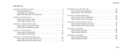
...see "Removing the Battery Pack" on page 14). 4. Loosen the three captive screws that secure the processor thermal fan to the computer base. 5. Replacing the Processor Thermal Fan 1. Replace the battery pack (see "Replacing the Compartment Door" on the computer, replace ...the computer. Failure to the computer. 5. Connect the processor thermal fan cable to the computer. 1 processor thermal fan 2 captive screws (3) CHAPTER 5: PROCESSOR THERMAL FAN 1 2 3 3 processor thermal fan cable connector 022 /022 Disconnect the processor thermal fan cable from the system board connector. 6. ...
...see "Removing the Battery Pack" on page 14). 4. Loosen the three captive screws that secure the processor thermal fan to the computer base. 5. Replacing the Processor Thermal Fan 1. Replace the battery pack (see "Replacing the Compartment Door" on the computer, replace ...the computer. Failure to the computer. 5. Connect the processor thermal fan cable to the computer. 1 processor thermal fan 2 captive screws (3) CHAPTER 5: PROCESSOR THERMAL FAN 1 2 3 3 processor thermal fan cable connector 022 /022 Disconnect the processor thermal fan cable from the system board connector. 6. ...

Service Manual
Page 78
...your warranty. CAUTION: To help prevent damage to servicing that shipped with your computer. Processor Heat Sink WARNING: Before working inside your computer, read the safety information that is not authorized by Dell™ is not covered by periodically touching an unpainted metal surface (such as a ...inside the computer. Damage due to the system board, remove the main battery (see the Regulatory Compliance Homepage at www.dell.com/regulatory_compliance. CAUTION: To avoid electrostatic discharge, ground yourself by using a wrist grounding strap or by your computer. CHAPTER 17...
...your warranty. CAUTION: To help prevent damage to servicing that shipped with your computer. Processor Heat Sink WARNING: Before working inside your computer, read the safety information that is not authorized by Dell™ is not covered by periodically touching an unpainted metal surface (such as a ...inside the computer. Damage due to the system board, remove the main battery (see the Regulatory Compliance Homepage at www.dell.com/regulatory_compliance. CAUTION: To avoid electrostatic discharge, ground yourself by using a wrist grounding strap or by your computer. CHAPTER 17...

Service Manual
Page 79
...page 47). 8. Remove the left and right brackets (see "Removing the Brackets" on page 6. 2. Loosen the six captive screws that secure the processor heat sink to the system board. 10. Remove the battery pack (see "Removing the Palm Rest" on page 11). 3. Remove the palm rest ... 14). 4. Remove the magnesium cover (see "Removing the Compartment Door" on page 50). 9. Lift the processor heat sink off the system board. 2 1 1 captive screws (6) CHAPTER 17: PROCESSOR HEAT SINK 2 processor heat sink 079 /079 Remove the center control cover (see "Removing the Keyboard" on page 33). 5. ...
...page 47). 8. Remove the left and right brackets (see "Removing the Brackets" on page 6. 2. Loosen the six captive screws that secure the processor heat sink to the system board. 10. Remove the battery pack (see "Removing the Palm Rest" on page 11). 3. Remove the palm rest ... 14). 4. Remove the magnesium cover (see "Removing the Compartment Door" on page 50). 9. Lift the processor heat sink off the system board. 2 1 1 captive screws (6) CHAPTER 17: PROCESSOR HEAT SINK 2 processor heat sink 079 /079 Remove the center control cover (see "Removing the Keyboard" on page 33). 5. ...

Service Manual
Page 80
... on page 35). 10. Replace the battery pack (see "Replacing the Center Control Cover" on page 52). 6. Replacing the Processor Heat Sink 1. NOTE: If the processor heat sink is replaced, the thermal cooling pads will be attached to the computer. Replace the center control cover (see "Replacing ...the Battery Pack" on page 39). 9. Follow the instructions in damage to the new processor heat sink. Peel the backing off the thermal cooling pads attached to the system board. 5. Tighten the six captive screws that no stray ...
... on page 35). 10. Replace the battery pack (see "Replacing the Center Control Cover" on page 52). 6. Replacing the Processor Heat Sink 1. NOTE: If the processor heat sink is replaced, the thermal cooling pads will be attached to the computer. Replace the center control cover (see "Replacing ...the Battery Pack" on page 39). 9. Follow the instructions in damage to the new processor heat sink. Peel the backing off the thermal cooling pads attached to the system board. 5. Tighten the six captive screws that no stray ...

Service Manual
Page 82
...system board, remove the main battery (see the Regulatory Compliance Homepage at www.dell.com/regulatory_compliance. CAUTION: To help prevent damage to servicing that shipped with your computer. Processor WARNING: Before working inside your computer, read the safety information that is not... authorized by Dell™ is not covered by periodically touching an unpainted metal surface (such as...
...system board, remove the main battery (see the Regulatory Compliance Homepage at www.dell.com/regulatory_compliance. CAUTION: To help prevent damage to servicing that shipped with your computer. Processor WARNING: Before working inside your computer, read the safety information that is not... authorized by Dell™ is not covered by periodically touching an unpainted metal surface (such as...

Service Manual
Page 83
... and right brackets (see "Removing the Compartment Door" on page 47). 8. Remove the processor heat sink (see "Removing the Center Control Cover" on page 42). 7. The ZIF-socket cam screw secures the processor to the cam stop. Follow the instructions in "Before You Begin" on page 79). ...Remove the center control cover (see "Removing the Processor Heat Sink" on page 6. 2. Lift the processor off the ZIF socket. 1 1 processor 2 pin-1 corner of the arrow on the ZIF-socket cam screw. 11. Remove the palm rest (see "...
... and right brackets (see "Removing the Compartment Door" on page 47). 8. Remove the processor heat sink (see "Removing the Center Control Cover" on page 42). 7. The ZIF-socket cam screw secures the processor to the cam stop. Follow the instructions in "Before You Begin" on page 79). ...Remove the center control cover (see "Removing the Processor Heat Sink" on page 6. 2. Lift the processor off the ZIF socket. 1 1 processor 2 pin-1 corner of the arrow on the ZIF-socket cam screw. 11. Remove the palm rest (see "...


