
Mobile Manual
Page 4
CONTENTS CHAPTER 3: USING YOUR LAPTOP 35 Alienware Command Center 36 Using Removable Media and Cards 39 Using the Wireless Control 40 Battery Pack 40 Power Management 41 nVidia Optimus Technology 43 Configuring the BIOS 45 CHAPTER 4: INSTALLING AND REPLACING COMPONENTS 55 Before You Begin 56 Replacing the Battery Pack 60 Upgrading or Replacing Memory 63 Upgrading or Replacing the Hard Drive Assembly 66 CHAPTER 5: TROUBLESHOOTING 71 Basic Hints and Tips 72 Backup and General Maintenance 73 Software Diagnostic Tools 75 Answers to Common Problems 78 4
CONTENTS CHAPTER 3: USING YOUR LAPTOP 35 Alienware Command Center 36 Using Removable Media and Cards 39 Using the Wireless Control 40 Battery Pack 40 Power Management 41 nVidia Optimus Technology 43 Configuring the BIOS 45 CHAPTER 4: INSTALLING AND REPLACING COMPONENTS 55 Before You Begin 56 Replacing the Battery Pack 60 Upgrading or Replacing Memory 63 Upgrading or Replacing the Hard Drive Assembly 66 CHAPTER 5: TROUBLESHOOTING 71 Basic Hints and Tips 72 Backup and General Maintenance 73 Software Diagnostic Tools 75 Answers to Common Problems 78 4
Mobile Manual
Page 45
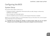
... after you write down the current System Setup information for future reference. CAUTION: Do not change a user-selectable option. • View the installed amount of memory or set the type of hard drive installed.
... after you write down the current System Setup information for future reference. CAUTION: Do not change a user-selectable option. • View the installed amount of memory or set the type of hard drive installed.
Mobile Manual
Page 48
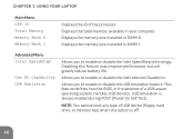
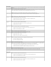
... device (floppy, hard drive, or memory key) when this feature may improve performance, but will greatly reduce battery life. Displays the memory size installed in DIMM 1. Displays the memory size installed in DIMM 0. Displays the total memory available in the absence of the processor.... CHAPTER 3: USING YOUR LAPTOP Main Menu CPU ID Total Memory Memory Bank 0 Memory Bank 1 Displays the ID of...
... device (floppy, hard drive, or memory key) when this feature may improve performance, but will greatly reduce battery life. Displays the memory size installed in DIMM 1. Displays the memory size installed in DIMM 0. Displays the total memory available in the absence of the processor.... CHAPTER 3: USING YOUR LAPTOP Main Menu CPU ID Total Memory Memory Bank 0 Memory Bank 1 Displays the ID of...

Mobile Manual
Page 63
The table below illustrates all the possible ways system memory can be configured. Memory connector #1 1 GB 1 GB 2 GB 4 GB Memory connector #2 1 GB 2 GB 2 GB 4 GB Total memory 2 GB 3 GB 4 GB 8 GB 63 The industry standard JEDEC PC3‑8500/PC3-10600 (DDR3) SODIMM memory module connectors are available for memory upgrade. CHAPTER 4: INSTALLING AND REPLACING COMPONENTS Upgrading or Replacing Memory Your laptop is equipped with a configurable memory unit.
The table below illustrates all the possible ways system memory can be configured. Memory connector #1 1 GB 1 GB 2 GB 4 GB Memory connector #2 1 GB 2 GB 2 GB 4 GB Total memory 2 GB 3 GB 4 GB 8 GB 63 The industry standard JEDEC PC3‑8500/PC3-10600 (DDR3) SODIMM memory module connectors are available for memory upgrade. CHAPTER 4: INSTALLING AND REPLACING COMPONENTS Upgrading or Replacing Memory Your laptop is equipped with a configurable memory unit.
Mobile Manual
Page 64
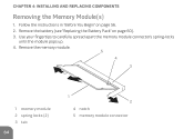
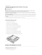
Follow the instructions in "Before You Begin" on page 60). 3. Use your fingertips to carefully spread apart the memory module connector's spring-locks until the module pops up. 4. Remove the battery (see "Replacing the Battery Pack" on page 56. 2. CHAPTER 4: INSTALLING AND REPLACING COMPONENTS Removing the Memory Module(s) 1. Remove the memory module. 5 4 3 1 memory module 2 spring locks (2) 3 tab 64 1 2 4 notch 5 memory module connector
Follow the instructions in "Before You Begin" on page 60). 3. Use your fingertips to carefully spread apart the memory module connector's spring-locks until the module pops up. 4. Remove the battery (see "Replacing the Battery Pack" on page 56. 2. CHAPTER 4: INSTALLING AND REPLACING COMPONENTS Removing the Memory Module(s) 1. Remove the memory module. 5 4 3 1 memory module 2 spring locks (2) 3 tab 64 1 2 4 notch 5 memory module connector

Mobile Manual
Page 65
NOTE: If the memory module is not installed properly, the computer may not boot. 65 NOTE: If you need to install memory modules in two connectors, install a memory module in the lower connector before you install a memory module in reverse order. CHAPTER 4: INSTALLING AND REPLACING COMPONENTS To replace the memory modules, perform the removal steps in the upper connector. While inserting the memory module into the connector align the notch on the memory module with the tab on the memory module connector.
NOTE: If the memory module is not installed properly, the computer may not boot. 65 NOTE: If you need to install memory modules in two connectors, install a memory module in the lower connector before you install a memory module in reverse order. CHAPTER 4: INSTALLING AND REPLACING COMPONENTS To replace the memory modules, perform the removal steps in the upper connector. While inserting the memory module into the connector align the notch on the memory module with the tab on the memory module connector.

Mobile Manual
Page 75
When the Alienware logo appears, press immediately. Select Diagnostics from the menu and press . ...operating system logo appears, continue to the next test, press ; Shut down the error code(s) and contact Alienware (for more information, see the Microsoft® Windows® desktop; To stop the assessment and restart the computer..., press ; NOTE: If you see "CONTACTING ALIENWARE" on (or restart) your computer. 2. CHAPTER 5: TROUBLESHOOTING Software Diagnostic Tools Pre-Boot System Assessment (PSA) The ...
When the Alienware logo appears, press immediately. Select Diagnostics from the menu and press . ...operating system logo appears, continue to the next test, press ; Shut down the error code(s) and contact Alienware (for more information, see the Microsoft® Windows® desktop; To stop the assessment and restart the computer..., press ; NOTE: If you see "CONTACTING ALIENWARE" on (or restart) your computer. 2. CHAPTER 5: TROUBLESHOOTING Software Diagnostic Tools Pre-Boot System Assessment (PSA) The ...

Mobile Manual
Page 76
... you begin. It is recommended that you contact Alienware for technical assistance. Start the Alienware Diagnostics from My DELL Downloads (downloadstore.dell.com/media) and create your laptop's configuration information, and ensure that the device that you print these procedures before you want to run the remaining memory tests? If you experience a problem with your...
... you begin. It is recommended that you contact Alienware for technical assistance. Start the Alienware Diagnostics from My DELL Downloads (downloadstore.dell.com/media) and create your laptop's configuration information, and ensure that the device that you print these procedures before you want to run the remaining memory tests? If you experience a problem with your...

Mobile Manual
Page 83
Reseat the memory modules if applicable (see "CONTACTING ALIENWARE" on page 109). Switch the video image: If your computer is recommended that you attach an external monitor to your computer supports, it is attached ... image to resume normal operation. Display If the display is blank NOTE: If you require assistance, contact Alienware Technical Support (for correct seating and orientation. If you are using a dual-channel memory configuration require that memory modules be in pairs. The computer may be installed in a power saving mode: Press a key on the...
Reseat the memory modules if applicable (see "CONTACTING ALIENWARE" on page 109). Switch the video image: If your computer is recommended that you attach an external monitor to your computer supports, it is attached ... image to resume normal operation. Display If the display is blank NOTE: If you require assistance, contact Alienware Technical Support (for correct seating and orientation. If you are using a dual-channel memory configuration require that memory modules be in pairs. The computer may be installed in a power saving mode: Press a key on the...

Mobile Manual
Page 93
CHAPTER 7: SPECIFICATIONS Processor and System Chipset Processor Intel® Core™ i3 Intel Core i5 Intel Core i7 L2 cache 256 KB L3 cache up to 4 MB Bus clock 133 Mhz System chipset Intel QS57 SDRAM bus width one or two 64-bit channels of DDR3 memory up to 1333 MHz Processor address bus width 32 bits Processor data width 64 bits BIOS EPROM 8 Mbit Graphics bus PCIe x16 bus PCI bus 32 bits 93
CHAPTER 7: SPECIFICATIONS Processor and System Chipset Processor Intel® Core™ i3 Intel Core i5 Intel Core i7 L2 cache 256 KB L3 cache up to 4 MB Bus clock 133 Mhz System chipset Intel QS57 SDRAM bus width one or two 64-bit channels of DDR3 memory up to 1333 MHz Processor address bus width 32 bits Processor data width 64 bits BIOS EPROM 8 Mbit Graphics bus PCIe x16 bus PCI bus 32 bits 93

Mobile Manual
Page 94
CHAPTER 7: SPECIFICATIONS Memory Connectors Capacities Memory type Memory configurations possible IEEE 1394 A IEEE 1394 A controller IEEE 1394 interface two internally-accessible DDR3 SODIMM sockets 1 GB, 2 GB, and 4 GB 1066 MHz and 1333 MHz (operates at 800 Mhz) dual‑channel DDR3 configurations 2 GB, 3 GB, 4 GB, and 8 GB JMicron JMB380 compliant with standard IEEE 1394a-2000 specification 94
CHAPTER 7: SPECIFICATIONS Memory Connectors Capacities Memory type Memory configurations possible IEEE 1394 A IEEE 1394 A controller IEEE 1394 interface two internally-accessible DDR3 SODIMM sockets 1 GB, 2 GB, and 4 GB 1066 MHz and 1333 MHz (operates at 800 Mhz) dual‑channel DDR3 configurations 2 GB, 3 GB, 4 GB, and 8 GB JMicron JMB380 compliant with standard IEEE 1394a-2000 specification 94

Mobile Manual
Page 96
up to 2 W total power single digital microphone in camera assembly program menus and keyboard media function keys 96 CHAPTER 7: SPECIFICATIONS Video Video controller Integrated Discrete Video memory Integrated Discrete External display support Intel QS57 Nvidia NV11P-GS1 dynamic based on system memory capacity 1 GB HDMI and DisplayPort Audio Controller Speaker Internal speaker amplifier Internal microphone support Volume controls Intel HDA single 8-ohms speakers in both the left and right speaker assembly up to 1 W per channel;
up to 2 W total power single digital microphone in camera assembly program menus and keyboard media function keys 96 CHAPTER 7: SPECIFICATIONS Video Video controller Integrated Discrete Video memory Integrated Discrete External display support Intel QS57 Nvidia NV11P-GS1 dynamic based on system memory capacity 1 GB HDMI and DisplayPort Audio Controller Speaker Internal speaker amplifier Internal microphone support Volume controls Intel HDA single 8-ohms speakers in both the left and right speaker assembly up to 1 W per channel;

Mobile Manual
Page 97
Hard-Drive Storage Interface Number of hard drives Hard drive Type Cards Supported Media cards Video cards CHAPTER 7: SPECIFICATIONS SATA one 2.5 inch SATA hard drive standard portable and solid-state hard-drives • Secure Digital (SD) memory card • MultiMedia Card (MMC) • Memory Stick PRO • Intel QS57 • Nvidia GeForce GT 335M (discrete) 97
Hard-Drive Storage Interface Number of hard drives Hard drive Type Cards Supported Media cards Video cards CHAPTER 7: SPECIFICATIONS SATA one 2.5 inch SATA hard drive standard portable and solid-state hard-drives • Secure Digital (SD) memory card • MultiMedia Card (MMC) • Memory Stick PRO • Intel QS57 • Nvidia GeForce GT 335M (discrete) 97
Service Manual
Page 1
... change without the written permission of these materials in trademarks and trade names other countries. Alienware is strictly forbidden. and is a registered trademark owned by Dell under license; Regulatory model: P06T series Regulatory type: P06T001/P06T002 June 2010 Rev. Trademarks... this document is subject to either trademarks or registered trademarks of Alienware Corporation; Reproduction of Dell Inc. Alienware® M11x R2 Service Manual Before You Begin Base Cover Battery Pack Hard Drive Memory Module(s) Wireless Mini-Card(s) Hinge Cover Keyboard Palm Rest Assembly ...
... change without the written permission of these materials in trademarks and trade names other countries. Alienware is strictly forbidden. and is a registered trademark owned by Dell under license; Regulatory model: P06T series Regulatory type: P06T001/P06T002 June 2010 Rev. Trademarks... this document is subject to either trademarks or registered trademarks of Alienware Corporation; Reproduction of Dell Inc. Alienware® M11x R2 Service Manual Before You Begin Base Cover Battery Pack Hard Drive Memory Module(s) Wireless Mini-Card(s) Hinge Cover Keyboard Palm Rest Assembly ...
Service Manual
Page 6
...or changeable configuration information for your laptop. Turn on your computer to work incorrectly. Back to Contents Page System Setup Alienware® M11x R2 Service Manual Configuring the System Setup Configuring the System Setup The System Setup options allow you to: l Change the system...keys and their functions within the active field. Displays the system date. Key functions appear at the bottom of time. Displays the memory size installed in DIMM 0. l Set or change a user-selectable option. Information is booting, press immediately before the operating system...
...or changeable configuration information for your laptop. Turn on your computer to work incorrectly. Back to Contents Page System Setup Alienware® M11x R2 Service Manual Configuring the System Setup Configuring the System Setup The System Setup options allow you to: l Change the system...keys and their functions within the active field. Displays the system date. Key functions appear at the bottom of time. Displays the memory size installed in DIMM 0. l Set or change a user-selectable option. Information is booting, press immediately before the operating system...
Service Manual
Page 7
.... This feature defines how the BIOS, in Battery Mode. SATA Operation Allows you to configure the operating mode of USB device (floppy, hard drive, or memory key) when this feature may not wake the computer. Use XD Capability Allows you to enable or disable the Intel eXecute Disable bit. USB Emulation...
.... This feature defines how the BIOS, in Battery Mode. SATA Operation Allows you to configure the operating mode of USB device (floppy, hard drive, or memory key) when this feature may not wake the computer. Use XD Capability Allows you to enable or disable the Intel eXecute Disable bit. USB Emulation...
Service Manual
Page 10
... 1 screw 2 Bluetooth card Replacing the Bluetooth Card 1. Removing the Bluetooth Card 1. Remove the memory module(s) (see Removing the Keyboard). 8. Remove the keyboard (see Removing the Memory Module(s)). 6. Follow the instructions in Before You Begin. 2. For additional safety best practices information,... www.dell.com/regulatory_compliance. Remove the base cover (see Removing the Palm Rest Assembly). 9. Remove the palm rest assembly (see Removing the Base Cover). 3. Back to Contents Page Internal Card With Bluetooth® Wireless Technology Alienware® M11x R2 Service ...
... 1 screw 2 Bluetooth card Replacing the Bluetooth Card 1. Removing the Bluetooth Card 1. Remove the memory module(s) (see Removing the Keyboard). 8. Remove the keyboard (see Removing the Memory Module(s)). 6. Follow the instructions in Before You Begin. 2. For additional safety best practices information,... www.dell.com/regulatory_compliance. Remove the base cover (see Removing the Palm Rest Assembly). 9. Remove the palm rest assembly (see Removing the Base Cover). 3. Back to Contents Page Internal Card With Bluetooth® Wireless Technology Alienware® M11x R2 Service ...

Service Manual
Page 11
..., replace all screws and ensure that secures the Bluetooth card to step 8 in damage to Contents Page Replace the memory module(s) (see Replacing the Base Cover). Replace the base cover (see Replacing the Memory Module(s)). 8. Back to the computer. 2. Replace the hinge cover (see Replacing the Keyboard). 6. CAUTION: Before turning on the...
..., replace all screws and ensure that secures the Bluetooth card to step 8 in damage to Contents Page Replace the memory module(s) (see Replacing the Base Cover). Replace the base cover (see Replacing the Memory Module(s)). 8. Back to the computer. 2. Replace the hinge cover (see Replacing the Keyboard). 6. CAUTION: Before turning on the...

Service Manual
Page 12
... Follow the instructions in Removing the Hard Drive. 5. Remove the base cover (see the Regulatory Compliance Homepage at www.dell.com/regulatory_compliance. Back to Contents Page Coin-Cell Battery Alienware® M11x R2 Service Manual Removing the Coin-Cell Battery Replacing the Coin-Cell Battery WARNING: Before working inside your computer, read the... the system board. 1 coin-cell battery cable connector 2 coin-cell battery Replacing the Coin-Cell Battery 1. Remove the keyboard (see Removing the Memory Module(s)). 6. Remove the memory module(s) (see Removing the Keyboard). 8.
... Follow the instructions in Removing the Hard Drive. 5. Remove the base cover (see the Regulatory Compliance Homepage at www.dell.com/regulatory_compliance. Back to Contents Page Coin-Cell Battery Alienware® M11x R2 Service Manual Removing the Coin-Cell Battery Replacing the Coin-Cell Battery WARNING: Before working inside your computer, read the... the system board. 1 coin-cell battery cable connector 2 coin-cell battery Replacing the Coin-Cell Battery 1. Remove the keyboard (see Removing the Memory Module(s)). 6. Remove the memory module(s) (see Removing the Keyboard). 8.
Service Manual
Page 13
Replace the palm rest assembly (see Replacing the Memory Module(s)). 8. Replace the memory module(s) (see Replacing the Palm Rest Assembly). 5. Replace the keyboard (see Replacing the Hinge Cover). 7. Failure to do so may result in Replacing the Hard ...
Replace the palm rest assembly (see Replacing the Memory Module(s)). 8. Replace the memory module(s) (see Replacing the Palm Rest Assembly). 5. Replace the keyboard (see Replacing the Hinge Cover). 7. Failure to do so may result in Replacing the Hard ...


