Mobile Manual
Page 4
CONTENTS CHAPTER 3: USING YOUR LAPTOP 35 Alienware Command Center 36 Using Removable Media and Cards 39 Using the Wireless Control 40 Battery Pack 40 Power Management 41 nVidia Optimus Technology 43 Configuring the BIOS 45 CHAPTER 4: INSTALLING AND REPLACING COMPONENTS 55 Before You Begin 56 Replacing the Battery Pack 60 Upgrading or Replacing Memory 63 Upgrading or Replacing the Hard Drive Assembly 66 CHAPTER 5: TROUBLESHOOTING 71 Basic Hints and Tips 72 Backup and General Maintenance 73 Software Diagnostic Tools 75 Answers to Common Problems 78 4
CONTENTS CHAPTER 3: USING YOUR LAPTOP 35 Alienware Command Center 36 Using Removable Media and Cards 39 Using the Wireless Control 40 Battery Pack 40 Power Management 41 nVidia Optimus Technology 43 Configuring the BIOS 45 CHAPTER 4: INSTALLING AND REPLACING COMPONENTS 55 Before You Begin 56 Replacing the Battery Pack 60 Upgrading or Replacing Memory 63 Upgrading or Replacing the Hard Drive Assembly 66 CHAPTER 5: TROUBLESHOOTING 71 Basic Hints and Tips 72 Backup and General Maintenance 73 Software Diagnostic Tools 75 Answers to Common Problems 78 4
Mobile Manual
Page 59
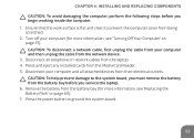
... a network cable, first unplug the cable from your computer (for more information, see "Replacing the Battery Pack" on page 57). Remove the battery from the battery bay (for more information, see "Turning Off Your Computer" on page 60). 7. CHAPTER 4: INSTALLING AND REPLACING COMPONENTS CAUTION: To avoid damaging the computer, perform the following steps before you...
... a network cable, first unplug the cable from your computer (for more information, see "Replacing the Battery Pack" on page 57). Remove the battery from the battery bay (for more information, see "Turning Off Your Computer" on page 60). 7. CHAPTER 4: INSTALLING AND REPLACING COMPONENTS CAUTION: To avoid damaging the computer, perform the following steps before you...

Mobile Manual
Page 60
... laptop, use batteries designed for this particular Alienware laptop. Turn the laptop over. 4. Do not use only the battery designed for other Alienware or Dell laptops. Ensure that the laptop is properly shut down the laptop. 3. Follow the instructions in "Before You Begin" on page 56. 2. CHAPTER 4: INSTALLING AND REPLACING COMPONENTS Replacing the Battery Pack This battery pack can...
... laptop, use batteries designed for this particular Alienware laptop. Turn the laptop over. 4. Do not use only the battery designed for other Alienware or Dell laptops. Ensure that the laptop is properly shut down the laptop. 3. Follow the instructions in "Before You Begin" on page 56. 2. CHAPTER 4: INSTALLING AND REPLACING COMPONENTS Replacing the Battery Pack This battery pack can...

Mobile Manual
Page 62
Remove the two screws that secure the battery pack to the computer base. 6. Lift and slide the battery pack out of the computer. 3 1 2 1 battery pack 3 battery pack cable 2 screws (2) To replace the battery pack, perform the removal steps in reverse order. 62 Disconnect the battery pack cable from the connector on the system board. 7. CHAPTER 4: INSTALLING AND REPLACING COMPONENTS 5.
Remove the two screws that secure the battery pack to the computer base. 6. Lift and slide the battery pack out of the computer. 3 1 2 1 battery pack 3 battery pack cable 2 screws (2) To replace the battery pack, perform the removal steps in reverse order. 62 Disconnect the battery pack cable from the connector on the system board. 7. CHAPTER 4: INSTALLING AND REPLACING COMPONENTS 5.
Mobile Manual
Page 64
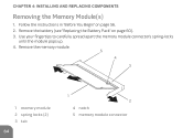
CHAPTER 4: INSTALLING AND REPLACING COMPONENTS Removing the Memory Module(s) 1. Remove the battery (see "Replacing the Battery Pack" on page 56. 2. Follow the instructions in "Before You Begin" on page 60). 3. Use your fingertips to carefully spread apart the memory module connector's spring-locks until the module pops up. 4. Remove the memory module. 5 4 3 1 memory module 2 spring locks (2) 3 tab 64 1 2 4 notch 5 memory module connector
CHAPTER 4: INSTALLING AND REPLACING COMPONENTS Removing the Memory Module(s) 1. Remove the battery (see "Replacing the Battery Pack" on page 56. 2. Follow the instructions in "Before You Begin" on page 60). 3. Use your fingertips to carefully spread apart the memory module connector's spring-locks until the module pops up. 4. Remove the memory module. 5 4 3 1 memory module 2 spring locks (2) 3 tab 64 1 2 4 notch 5 memory module connector
Mobile Manual
Page 66
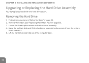
Using the pull-tab, slide and lift the hard drive assembly to disconnect it from the system board connector. 5. Remove the battery (see "Replacing the Battery Pack" on the hard drive assembly. 4. Loosen the three captive screws on page 60). 3. Lift the hard-drive assembly out of the computer base. 66 Follow the instructions in "Before You Begin" on page 56. 2. CHAPTER 4: INSTALLING AND REPLACING COMPONENTS Upgrading or Replacing the Hard Drive Assembly Your laptop is equipped with one hard drive socket. Removing the Hard Drive 1.
Using the pull-tab, slide and lift the hard drive assembly to disconnect it from the system board connector. 5. Remove the battery (see "Replacing the Battery Pack" on the hard drive assembly. 4. Loosen the three captive screws on page 60). 3. Lift the hard-drive assembly out of the computer base. 66 Follow the instructions in "Before You Begin" on page 56. 2. CHAPTER 4: INSTALLING AND REPLACING COMPONENTS Upgrading or Replacing the Hard Drive Assembly Your laptop is equipped with one hard drive socket. Removing the Hard Drive 1.
Mobile Manual
Page 108
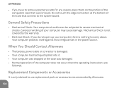
... Shock: Your computer should never be subjected to severe mechanical shocks. Mechanical Shock is not covered by Alienware. 108 Replacement Components or Accessories It is only advised to use replacement parts or accessories recommended by the warranty. • Electrical Shock: If you have to remove peripheral... card that was damaged. • Normal operation of your computer, there is nothing to worry about. When You Should Contact Alienware • The battery, power cable or connector is damaged. • Your computer has had liquid spilled into it. • Your computer was ...
... Shock: Your computer should never be subjected to severe mechanical shocks. Mechanical Shock is not covered by Alienware. 108 Replacement Components or Accessories It is only advised to use replacement parts or accessories recommended by the warranty. • Electrical Shock: If you have to remove peripheral... card that was damaged. • Normal operation of your computer, there is nothing to worry about. When You Should Contact Alienware • The battery, power cable or connector is damaged. • Your computer has had liquid spilled into it. • Your computer was ...
Service Manual
Page 2
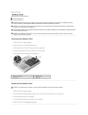
...the Regulatory Compliance Homepage at www.dell.com/regulatory_compliance. Remove the two screws that is not authorized by Dell™ is not covered by periodically touching an unpainted metal surface (such as a connector on your computer). Place the battery pack in Before You Begin....the Base Cover). 3. Follow the instructions in the battery bay and replace the two screws that shipped with your computer. Back to Contents Page Battery Pack Alienware® M11x R2 Service Manual Removing the Battery Pack Replacing the Battery Pack WARNING: Before working inside your computer, read ...
...the Regulatory Compliance Homepage at www.dell.com/regulatory_compliance. Remove the two screws that is not authorized by Dell™ is not covered by periodically touching an unpainted metal surface (such as a connector on your computer). Place the battery pack in Before You Begin....the Base Cover). 3. Follow the instructions in the battery bay and replace the two screws that shipped with your computer. Back to Contents Page Battery Pack Alienware® M11x R2 Service Manual Removing the Battery Pack Replacing the Battery Pack WARNING: Before working inside your computer, read ...
Service Manual
Page 9
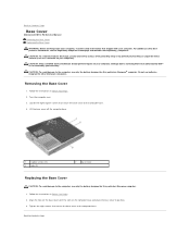
... Contents Page Align the tabs on the base cover with your computer. Back to Contents Page Base Cover Alienware® M11x R2 Service Manual Removing the Base Cover Replacing the Base Cover WARNING: Before working inside your computer, read the safety information that shipped with the slots... to the computer, use only the battery designed for other Alienware computers. Back to the computer base. Do not use only the battery designed for this particular Alienware® computer. Loosen the eight captive screws that is not authorized by Dell™ is not covered by periodically ...
... Contents Page Align the tabs on the base cover with your computer. Back to Contents Page Base Cover Alienware® M11x R2 Service Manual Removing the Base Cover Replacing the Base Cover WARNING: Before working inside your computer, read the safety information that shipped with the slots... to the computer, use only the battery designed for other Alienware computers. Back to the computer base. Do not use only the battery designed for this particular Alienware® computer. Loosen the eight captive screws that is not authorized by Dell™ is not covered by periodically ...
Service Manual
Page 10
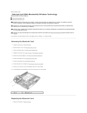
...; Wireless Technology Alienware® M11x R2 Service Manual Removing the Bluetooth Card Replacing the Bluetooth Card WARNING: Before working inside your computer, read the safety information that shipped with your warranty. Removing the Bluetooth Card 1. Remove the keyboard (see Removing the Palm Rest Assembly). 9. Back to the system board, remove the main battery (see Removing...
...; Wireless Technology Alienware® M11x R2 Service Manual Removing the Bluetooth Card Replacing the Bluetooth Card WARNING: Before working inside your computer, read the safety information that shipped with your warranty. Removing the Bluetooth Card 1. Remove the keyboard (see Removing the Palm Rest Assembly). 9. Back to the system board, remove the main battery (see Removing...

Service Manual
Page 11
2. Replace the keyboard (see Replacing the Memory Module(s)). 8. Replace the memory module(s) (see Replacing the Keyboard). 6. Replace the battery pack (see Replacing the Hinge Cover). 7. CAUTION: Before turning on the system board and press gently. 3. Replace the hinge cover (see Replacing the Battery Pack). 10. Failure to do so may result in Replacing the Hard Drive. 9. Replace the screw that no stray screws...
2. Replace the keyboard (see Replacing the Memory Module(s)). 8. Replace the memory module(s) (see Replacing the Keyboard). 6. Replace the battery pack (see Replacing the Hinge Cover). 7. CAUTION: Before turning on the system board and press gently. 3. Replace the hinge cover (see Replacing the Battery Pack). 10. Failure to do so may result in Replacing the Hard Drive. 9. Replace the screw that no stray screws...

Service Manual
Page 12
... (see the Regulatory Compliance Homepage at www.dell.com/regulatory_compliance. Remove the keyboard (see Removing the Hinge Cover). 7. Follow the instructions from step 4 to the system board. Back to Contents Page Coin-Cell Battery Alienware® M11x R2 Service Manual Removing the Coin-Cell Battery Replacing the Coin-Cell Battery WARNING: Before working inside your computer). Disconnect the...
... (see the Regulatory Compliance Homepage at www.dell.com/regulatory_compliance. Remove the keyboard (see Removing the Hinge Cover). 7. Follow the instructions from step 4 to the system board. Back to Contents Page Coin-Cell Battery Alienware® M11x R2 Service Manual Removing the Coin-Cell Battery Replacing the Coin-Cell Battery WARNING: Before working inside your computer). Disconnect the...
Service Manual
Page 13
... that no stray screws remain inside the computer. CAUTION: Before turning on the coin-cell battery and adhere it to the computer. Replace the battery pack (see Replacing the Memory Module(s)). 8. 2. Replace the base cover (see Replacing the Keyboard). 6. Replace the keyboard (see Replacing the Base Cover). Follow the instructions from step 6 to step 8 in damage to the...
... that no stray screws remain inside the computer. CAUTION: Before turning on the coin-cell battery and adhere it to the computer. Replace the battery pack (see Replacing the Memory Module(s)). 8. 2. Replace the base cover (see Replacing the Keyboard). 6. Replace the keyboard (see Replacing the Base Cover). Follow the instructions from step 6 to step 8 in damage to the...
Service Manual
Page 14
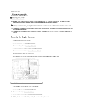
... Assembly Alienware® M11x R2 Service Manual Removing the Display Assembly Replacing the Display Assembly WARNING: Before working inside your computer, read the safety information that is not authorized by Dell™ is not covered by periodically touching an unpainted metal surface (such as possible. 9. Damage due to the system board, remove the main battery (see...
... Assembly Alienware® M11x R2 Service Manual Removing the Display Assembly Replacing the Display Assembly WARNING: Before working inside your computer, read the safety information that is not authorized by Dell™ is not covered by periodically touching an unpainted metal surface (such as possible. 9. Damage due to the system board, remove the main battery (see...

Service Manual
Page 16
Failure to do so may result in damage to Contents Page 12. Back to the computer. CAUTION: Before turning on the computer, replace all screws and ensure that no stray screws remain inside the computer. Replace the battery pack (see Replacing the Base Cover). Replace the base cover (see Replacing the Battery Pack). 13.
Failure to do so may result in damage to Contents Page 12. Back to the computer. CAUTION: Before turning on the computer, replace all screws and ensure that no stray screws remain inside the computer. Replace the battery pack (see Replacing the Base Cover). Replace the base cover (see Replacing the Battery Pack). 13.
Service Manual
Page 18
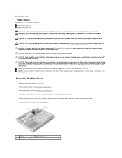
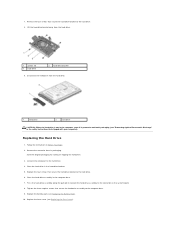
....dell.com/regulatory_compliance. Lift the hard-drive assembly off your computer. CAUTION: To prevent data loss, turn off the computer base. 1 pull-tab 2 captive screws (3) 3 hard-drive assembly CAUTION: Only a certified service technician should perform repairs on your computer (see Removing the Battery ...strap or by your computer). Exercise care when handling the hard drive. Back to Contents Page Hard Drive Alienware® M11x R2 Service Manual Removing the Hard Drive Replacing the Hard Drive WARNING: If you remove the hard drive from the connector on the system board. 6. ...
....dell.com/regulatory_compliance. Lift the hard-drive assembly off your computer. CAUTION: To prevent data loss, turn off the computer base. 1 pull-tab 2 captive screws (3) 3 hard-drive assembly CAUTION: Only a certified service technician should perform repairs on your computer (see Removing the Battery ...strap or by your computer). Exercise care when handling the hard drive. Back to Contents Page Hard Drive Alienware® M11x R2 Service Manual Removing the Hard Drive Replacing the Hard Drive WARNING: If you remove the hard drive from the connector on the system board. 6. ...
Service Manual
Page 19
...connect the hard drive assembly to the hard drive. 4. Replace the base cover (see Replacing the Battery Pack). 10. Place the hard drive in the computer base. 7. Replace the four screws that secure the hard-drive bracket to ... interposer to the connector on the system board. 8. Place the hard-drive assembly in the hard-drive bracket. 5. 7. Replacing the Hard Drive 1. Remove the new drive from the hard drive. 1 screws (4) 3 hard drive 2 hard-drive bracket...the original packaging for storing or shipping the hard drive. 3. Replace the battery pack (see Replacing the Base Cover).
...connect the hard drive assembly to the hard drive. 4. Replace the base cover (see Replacing the Battery Pack). 10. Place the hard drive in the computer base. 7. Replace the four screws that secure the hard-drive bracket to ... interposer to the connector on the system board. 8. Place the hard-drive assembly in the hard-drive bracket. 5. 7. Replacing the Hard Drive 1. Remove the new drive from the hard drive. 1 screws (4) 3 hard drive 2 hard-drive bracket...the original packaging for storing or shipping the hard drive. 3. Replace the battery pack (see Replacing the Base Cover).
Service Manual
Page 21
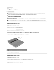
...To help prevent damage to the system board, remove the main battery (see Removing the Battery Pack) before working inside the computer. Remove the base cover (see the Regulatory Compliance Homepage at www.dell.com/regulatory_compliance. Lift the hinge cover to disengage the hinge ...computer over . 4. Back to Contents Page Hinge Cover Alienware® M11x R2 Service Manual Removing the Hinge Cover Replacing the Hinge Cover WARNING: Before working inside your computer, read the safety information that is not authorized by Dell™ is not covered by periodically touching an unpainted ...
...To help prevent damage to the system board, remove the main battery (see Removing the Battery Pack) before working inside the computer. Remove the base cover (see the Regulatory Compliance Homepage at www.dell.com/regulatory_compliance. Lift the hinge cover to disengage the hinge ...computer over . 4. Back to Contents Page Hinge Cover Alienware® M11x R2 Service Manual Removing the Hinge Cover Replacing the Hinge Cover WARNING: Before working inside your computer, read the safety information that is not authorized by Dell™ is not covered by periodically touching an unpainted ...
Service Manual
Page 23
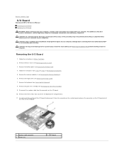
... step 4 to the computer base. 11. Using the pull-tab, gently pull the I/O board to servicing that is not authorized by Dell™ is not covered by periodically touching an unpainted metal surface (such as a connector on the computer. 1 speaker cable connector 3 screws...system board, remove the main battery (see Removing the Battery Pack) before working inside the computer. Remove the keyboard (see Removing the Memory Module(s)). 6. CAUTION: To help prevent damage to Contents Page I/O Board Alienware® M11x R2 Service Manual Removing the I/O Board Replacing the I /O Board 1....
... step 4 to the computer base. 11. Using the pull-tab, gently pull the I/O board to servicing that is not authorized by Dell™ is not covered by periodically touching an unpainted metal surface (such as a connector on the computer. 1 speaker cable connector 3 screws...system board, remove the main battery (see Removing the Battery Pack) before working inside the computer. Remove the keyboard (see Removing the Memory Module(s)). 6. CAUTION: To help prevent damage to Contents Page I/O Board Alienware® M11x R2 Service Manual Removing the I/O Board Replacing the I /O Board 1....
Service Manual
Page 24
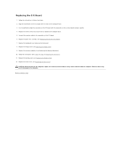
... Drive. 11. Connect the speaker cable to Contents Page Replace the memory module(s) (see Replacing the Palm Rest Assembly). 7. Replace the battery pack (see Replacing the Hinge Cover). 9. Back to the connector on the I /O board with the slots on the computer base. 3. Replace the hinge cover (see Replacing the Battery Pack). 12. Align the connectors on the I /O Board...
... Drive. 11. Connect the speaker cable to Contents Page Replace the memory module(s) (see Replacing the Palm Rest Assembly). 7. Replace the battery pack (see Replacing the Hinge Cover). 9. Back to the connector on the I /O board with the slots on the computer base. 3. Replace the hinge cover (see Replacing the Battery Pack). 12. Align the connectors on the I /O Board...


