Service Manual
Page 6
... assembly 59 Prerequisites...59 Procedure...59 Replacing the heat-sink assembly 61 Procedure...61 Post-requisites...62 Removing the power-adapter port 63 Prerequisites...63 Procedure...63 Replacing the power-adapter port 64 Procedure...64 Post-requisites...64 Removing the power-button board 65 Prerequisites...65 Procedure...65 Replacing the power-button...
... assembly 59 Prerequisites...59 Procedure...59 Replacing the heat-sink assembly 61 Procedure...61 Post-requisites...62 Removing the power-adapter port 63 Prerequisites...63 Procedure...63 Replacing the power-adapter port 64 Procedure...64 Post-requisites...64 Removing the power-button board 65 Prerequisites...65 Procedure...65 Replacing the power-button...
Service Manual
Page 8
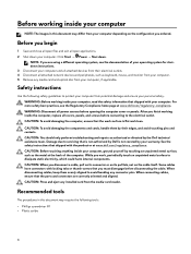
... applications. 2 Shut down . Some cables have connectors with locking tabs or thumb-screws that shipped with the product or at www.dell.com/regulatory_compliance. Safety instructions Use the following tools: • Phillips screwdriver #1 • Plastic scribe 8 When disconnecting cables, keep...card reader. NOTE: If you ordered. When connecting cables, ensure that the ports and connectors are using a different operating system, see the Regulatory Compliance home page at www.dell.com/regulatory_compliance. Before working inside your computer NOTE: The images in this ...
... applications. 2 Shut down . Some cables have connectors with locking tabs or thumb-screws that shipped with the product or at www.dell.com/regulatory_compliance. Safety instructions Use the following tools: • Phillips screwdriver #1 • Plastic scribe 8 When disconnecting cables, keep...card reader. NOTE: If you ordered. When connecting cables, ensure that the ports and connectors are using a different operating system, see the Regulatory Compliance home page at www.dell.com/regulatory_compliance. Before working inside your computer NOTE: The images in this ...
Service Manual
Page 9
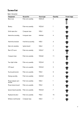
... M2.5x8 Tron-light holder Palm-rest assembly I/O board Palm-rest assembly Touch-pad bracket Display assembly Palm-rest assembly Palm-rest assembly Power-adapter port bracket Power-button board Palm-rest assembly Palm-rest assembly System-board assembly Palm-rest assembly Keyboard bracket Palm-rest assembly Wireless-card bracket Computer...
... M2.5x8 Tron-light holder Palm-rest assembly I/O board Palm-rest assembly Touch-pad bracket Display assembly Palm-rest assembly Palm-rest assembly Power-adapter port bracket Power-button board Palm-rest assembly Palm-rest assembly System-board assembly Palm-rest assembly Keyboard bracket Palm-rest assembly Wireless-card bracket Computer...
Service Manual
Page 47
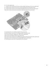
... the tape to access the coin-cell battery cable on the system board. 13 Disconnect the power-adapter port cable from the system board. 14 Disconnect the speaker cable from the system board. 15 Open the latch and disconnect the RGB per key keyboard cable (optional) from the system board. 16 Open...
... the tape to access the coin-cell battery cable on the system board. 13 Disconnect the power-adapter port cable from the system board. 14 Disconnect the speaker cable from the system board. 15 Open the latch and disconnect the RGB per key keyboard cable (optional) from the system board. 16 Open...
Service Manual
Page 48
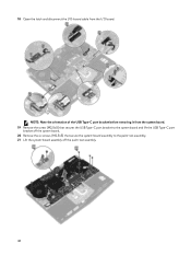
18 Open the latch and disconnect the I/O-board cable from the system board. 19 Remove the screw (M2.5x5) that secures the USB Type-C port bracket to the system board and lift the USB Type-C port bracket off the system board. 20 Remove the six screws (M2.5x5) that secure the system-board assembly to the palm-rest assembly. 21 Lift the system-board assembly off the palm-rest assembly. 48 NOTE: Note the orientation of the USB Type-C port bracket before removing it from the I/O board.
18 Open the latch and disconnect the I/O-board cable from the system board. 19 Remove the screw (M2.5x5) that secures the USB Type-C port bracket to the system board and lift the USB Type-C port bracket off the system board. 20 Remove the six screws (M2.5x5) that secure the system-board assembly to the palm-rest assembly. 21 Lift the system-board assembly off the palm-rest assembly. 48 NOTE: Note the orientation of the USB Type-C port bracket before removing it from the I/O board.
Service Manual
Page 50
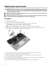
...to the system board. 6 Slide the I/O-board cable into the connector and press down the latch to secure the cable. 11 Connect the power-adapter port cable to the system board. 12 Route the coin-cell battery through the routing channel and adhere the tape to secure the cable. 50 For... more safety best practices, see the Regulatory Compliance home page at www.dell.com/regulatory_compliance. You must enter the Service Tag in Before working inside your computer. After working inside your computer, follow the steps in the ...
...to the system board. 6 Slide the I/O-board cable into the connector and press down the latch to secure the cable. 11 Connect the power-adapter port cable to the system board. 12 Route the coin-cell battery through the routing channel and adhere the tape to secure the cable. 50 For... more safety best practices, see the Regulatory Compliance home page at www.dell.com/regulatory_compliance. You must enter the Service Tag in Before working inside your computer. After working inside your computer, follow the steps in the ...
Service Manual
Page 63
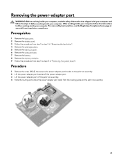
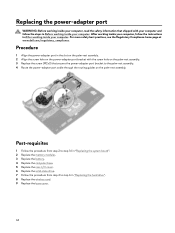
..., read the safety information that secures the power-adapter port bracket to the palm-rest assembly. 2 Lift the power-adapter port bracket off the power-adapter port. 3 Lift the power-adapter port off the palm-rest assembly. 4 Note the routing and remove the power-adapter port cable from step 1 to step 3 in "Removing ... from the routing guides on the palm-rest assembly. 63 For more safety best practices, see the Regulatory Compliance home page at www.dell.com/regulatory_compliance. After working inside your computer, follow the steps in Before working inside your computer.
..., read the safety information that secures the power-adapter port bracket to the palm-rest assembly. 2 Lift the power-adapter port bracket off the power-adapter port. 3 Lift the power-adapter port off the palm-rest assembly. 4 Note the routing and remove the power-adapter port cable from step 1 to step 3 in "Removing ... from the routing guides on the palm-rest assembly. 63 For more safety best practices, see the Regulatory Compliance home page at www.dell.com/regulatory_compliance. After working inside your computer, follow the steps in Before working inside your computer.
Service Manual
Page 64
... the routing guides on the power-adapter port bracket with your computer and follow the instructions in After working inside your computer. For more safety best practices, see the Regulatory Compliance home page at www.dell.com/regulatory_compliance. After working inside your computer..., follow the steps in Before working inside your computer. Replacing the power-adapter port WARNING: Before working inside your computer, read the safety information ...
... the routing guides on the power-adapter port bracket with your computer and follow the instructions in After working inside your computer. For more safety best practices, see the Regulatory Compliance home page at www.dell.com/regulatory_compliance. After working inside your computer..., follow the steps in Before working inside your computer. Replacing the power-adapter port WARNING: Before working inside your computer, read the safety information ...
Service Manual
Page 67
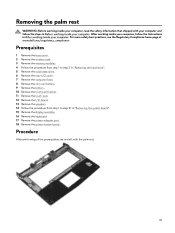
... your computer, follow the steps in Before working inside your computer. For more safety best practices, see the Regulatory Compliance home page at www.dell.com/regulatory_compliance. Prerequisites 1 Remove the base cover. 2 Remove the wireless card. 3 Remove the memory modules. 4 Follow the procedure from step... we are left with your computer and follow the instructions in "Removing the system board". 15 Remove the display assembly. 16 Remove the keyboard. 17 Remove the power-adapter port. 18 Remove the power-button board . Removing the palm rest WARNING: Before working inside your...
... your computer, follow the steps in Before working inside your computer. For more safety best practices, see the Regulatory Compliance home page at www.dell.com/regulatory_compliance. Prerequisites 1 Remove the base cover. 2 Remove the wireless card. 3 Remove the memory modules. 4 Follow the procedure from step... we are left with your computer and follow the instructions in "Removing the system board". 15 Remove the display assembly. 16 Remove the keyboard. 17 Remove the power-adapter port. 18 Remove the power-button board . Removing the palm rest WARNING: Before working inside your...
Service Manual
Page 68
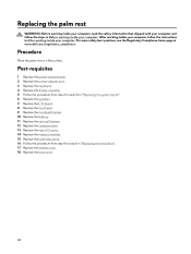
For more safety best practices, see the Regulatory Compliance home page at www.dell.com/regulatory_compliance. Post-requisites 1 Replace the power-button board. 2 Replace the power-adapter port. 3 Replace the keyboard. 4 Replace the display assembly. 5 Follow the procedure from step 2 to step 16 in "Replacing the system board"....battery. 11 Replace the coin-cell battery. 12 Replace the computer base. 13 Replace the rear-I/O cover. 14 Replace the memory modules. 15 Replace the solid-state drive. 16 Follow the procedure from step 4 to step 6 in "Replacing the hard drive". 17 Replace the wireless...
For more safety best practices, see the Regulatory Compliance home page at www.dell.com/regulatory_compliance. Post-requisites 1 Replace the power-button board. 2 Replace the power-adapter port. 3 Replace the keyboard. 4 Replace the display assembly. 5 Follow the procedure from step 2 to step 16 in "Replacing the system board"....battery. 11 Replace the coin-cell battery. 12 Replace the computer base. 13 Replace the rear-I/O cover. 14 Replace the memory modules. 15 Replace the solid-state drive. 16 Follow the procedure from step 4 to step 6 in "Replacing the hard drive". 17 Replace the wireless...
Service Manual
Page 79
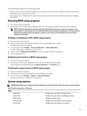
The BIOS setup program is displayed on the right pane. 4 Select or clear the Enable External USB Port check box to enter the BIOS setup program. The USB configuration is displayed. 3 On the left pane, select Settings → General → System ... pane, select Settings → System Configuration → USB Configuration. Entering BIOS setup program 1 Turn on (or restart) your computer. 2 During POST, when the DELL logo is displayed on your computer. If you must watch for the following purposes: • Get information about the hardware installed in the General group...
The BIOS setup program is displayed on the right pane. 4 Select or clear the Enable External USB Port check box to enter the BIOS setup program. The USB configuration is displayed. 3 On the left pane, select Settings → General → System ... pane, select Settings → System Configuration → USB Configuration. Entering BIOS setup program 1 Turn on (or restart) your computer. 2 During POST, when the DELL logo is displayed on your computer. If you must watch for the following purposes: • Get information about the hardware installed in the General group...
Service Manual
Page 86
Camera is enabled or disabled. • Solid white - Caps Lock status light: Indicates whether Caps Lock is not in use. Network port light: Indicates network connectivity. • Off - No network connection. • Solid green - 10 Mbps connection. • Solid orange - 100 Mbps connection. • Solid yellow - 1000 ...
Camera is enabled or disabled. • Solid white - Caps Lock status light: Indicates whether Caps Lock is not in use. Network port light: Indicates network connectivity. • Off - No network connection. • Solid green - 10 Mbps connection. • Solid orange - 100 Mbps connection. • Solid yellow - 1000 ...
Setup and Specifications
Page 3
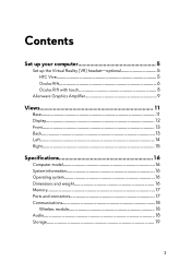
Contents Set up your computer 5 Set up the Virtual Reality (VR) headset-optional 5 HTC Vive 5 Oculus Rift 6 Oculus Rift with touch 8 Alienware Graphics Amplifier 9 Views 11 Base 11 Display 12 Front 13 Back 13 Left 14 Right 15 Specifications 16 Computer model 16 System information 16 Operating system 16 Dimensions and weight 16 Memory 17 Ports and connectors 17 Communications 18 Wireless module 18 Audio 18 Storage 19 3
Contents Set up your computer 5 Set up the Virtual Reality (VR) headset-optional 5 HTC Vive 5 Oculus Rift 6 Oculus Rift with touch 8 Alienware Graphics Amplifier 9 Views 11 Base 11 Display 12 Front 13 Back 13 Left 14 Right 15 Specifications 16 Computer model 16 System information 16 Operating system 16 Dimensions and weight 16 Memory 17 Ports and connectors 17 Communications 18 Wireless module 18 Audio 18 Storage 19 3
Setup and Specifications
Page 6
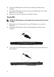
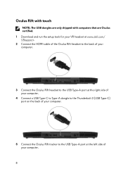
... NOTE: The USB dongles are only shipped with computers that are Oculus certified. 1 Download and run the setup tools for your VR headset at www.dell.com/ VRsupport. 2 Connect the HDMI cable of the Oculus Rift headset to the back of your computer. 3 Connect the Oculus Rift headset to the USB... Type-A port at the right side of your computer. 4 Follow the on-screen instructions to the USB 3.1 Gen 1 port at the right side of your computer. 6 2 Connect the HDMI cable of the HTC Vive headset to...
... NOTE: The USB dongles are only shipped with computers that are Oculus certified. 1 Download and run the setup tools for your VR headset at www.dell.com/ VRsupport. 2 Connect the HDMI cable of the Oculus Rift headset to the back of your computer. 3 Connect the Oculus Rift headset to the USB... Type-A port at the right side of your computer. 4 Follow the on-screen instructions to the USB 3.1 Gen 1 port at the right side of your computer. 6 2 Connect the HDMI cable of the HTC Vive headset to...
Setup and Specifications
Page 7
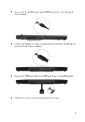
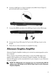
4 Connect the Oculus Rift tracker to the USB Type-A port at the left side of your computer. 5 Connect a USB Type-C to Type-A dongle to the Thunderbolt 3 (USB Type-C) port at the back of your computer. 6 Connect the XBOX controller to the USB Type-A port on the USB dongle. 7 Follow the on-screen instructions to complete the setup. 7
4 Connect the Oculus Rift tracker to the USB Type-A port at the left side of your computer. 5 Connect a USB Type-C to Type-A dongle to the Thunderbolt 3 (USB Type-C) port at the back of your computer. 6 Connect the XBOX controller to the USB Type-A port on the USB dongle. 7 Follow the on-screen instructions to complete the setup. 7
Setup and Specifications
Page 8
Oculus Rift with touch NOTE: The USB dongles are only shipped with computers that are Oculus certified. 1 Download and run the setup tools for your VR headset at www.dell.com/ VRsupport. 2 Connect the HDMI cable of the Oculus Rift headset to the back of your computer. 3 Connect the Oculus Rift headset to the USB Type-A port at the right side of your computer. 4 Connect a USB Type-C to Type-A dongle to the Thunderbolt 3 (USB Type-C) port on the back of your computer. 5 Connect the Oculus Rift tracker to the USB Type-A port at the left side of your computer. 8
Oculus Rift with touch NOTE: The USB dongles are only shipped with computers that are Oculus certified. 1 Download and run the setup tools for your VR headset at www.dell.com/ VRsupport. 2 Connect the HDMI cable of the Oculus Rift headset to the back of your computer. 3 Connect the Oculus Rift headset to the USB Type-A port at the right side of your computer. 4 Connect a USB Type-C to Type-A dongle to the Thunderbolt 3 (USB Type-C) port on the back of your computer. 5 Connect the Oculus Rift tracker to the USB Type-A port at the left side of your computer. 8
Setup and Specifications
Page 9
... VR headset can be connected either to your computer or your Alienware Graphics Amplifier. Alienware Graphics Amplifier Alienware Graphics Amplifier enables you are connecting the USB 3.0 cables on your VR headset to the USB 3.0 Type-A port on your Alienware Graphics Amplifier. 9 NOTE: The USB dongle is not required,...to your computer. 7 Connect the XBOX controller to the USB Type-A port on the USB dongle. 8 Connect the Oculus Rift tracker for Touch to the USB Type-A port on the dongle. 9 Follow the on your Alienware Graphics Amplifier. When using the Virtual Reality (VR) headset, connect ...
... VR headset can be connected either to your computer or your Alienware Graphics Amplifier. Alienware Graphics Amplifier Alienware Graphics Amplifier enables you are connecting the USB 3.0 cables on your VR headset to the USB 3.0 Type-A port on your Alienware Graphics Amplifier. 9 NOTE: The USB dongle is not required,...to your computer. 7 Connect the XBOX controller to the USB Type-A port on the USB dongle. 8 Connect the Oculus Rift tracker for Touch to the USB Type-A port on the dongle. 9 Follow the on your Alienware Graphics Amplifier. When using the Virtual Reality (VR) headset, connect ...
Setup and Specifications
Page 13
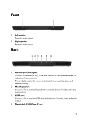
The two lights next to the connector indicate the connectivity status and network activity. 2 Mini DisplayPort Connect a TV or another HDMI-in enabled device. Front 1 Left speaker Provides audio output. 2 Right speaker Provides audio output. Back 1 Network port (with lights) Connect an Ethernet (RJ45) cable from a router or a broadband modem for network or Internet access. Provides video and audio output. 4 Thunderbolt 3 (USB Type-C) port 13 Provides video and audio output. 3 HDMI port Connect a TV or another DisplayPort-in enabled device.
The two lights next to the connector indicate the connectivity status and network activity. 2 Mini DisplayPort Connect a TV or another HDMI-in enabled device. Front 1 Left speaker Provides audio output. 2 Right speaker Provides audio output. Back 1 Network port (with lights) Connect an Ethernet (RJ45) cable from a router or a broadband modem for network or Internet access. Provides video and audio output. 4 Thunderbolt 3 (USB Type-C) port 13 Provides video and audio output. 3 HDMI port Connect a TV or another DisplayPort-in enabled device.
Setup and Specifications
Page 14
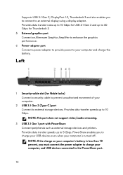
... your computer is turned off. Left 1 Security-cable slot (for Thunderbolt 3. 5 External graphics port Connect an Alienware Graphics Amplifier to enhance the graphics performance. 6 Power-adapter port Connect a power adapter to provide power to your computer. 2 USB 3.1 Gen 2 (Type-C) port Connect to external storage devices. Provides data transfer speeds up to 10 Gbps. NOTE...
... your computer is turned off. Left 1 Security-cable slot (for Thunderbolt 3. 5 External graphics port Connect an Alienware Graphics Amplifier to enhance the graphics performance. 6 Power-adapter port Connect a power adapter to provide power to your computer. 2 USB 3.1 Gen 2 (Type-C) port Connect to external storage devices. Provides data transfer speeds up to 10 Gbps. NOTE...
Setup and Specifications
Page 15
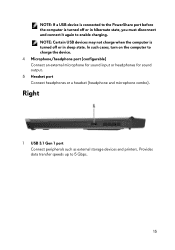
...) Connect an external microphone for sound input or headphones for sound output. 5 Headset port Connect headphones or a headset (headphone and microphone combo). In such cases, turn on the computer to 5 Gbps. 15 NOTE: Certain USB devices may not charge when the computer is turned off or in hibernate state,... you must disconnect and connect it again to enable charging. NOTE: If a USB device is connected to the PowerShare port before the computer is turned off ...
...) Connect an external microphone for sound input or headphones for sound output. 5 Headset port Connect headphones or a headset (headphone and microphone combo). In such cases, turn on the computer to 5 Gbps. 15 NOTE: Certain USB devices may not charge when the computer is turned off or in hibernate state,... you must disconnect and connect it again to enable charging. NOTE: If a USB device is connected to the PowerShare port before the computer is turned off ...


