Handling swollen Lithium-ion batteries
Page 1
...: A05 Release Date: 2020-06-11 Previous Release Version: A04 Like most laptops, Dell laptops use of the applicable warranty or service contract, including options for a slim form factor (especially with your Dell computer. When the system will no longer power on when the power button is pressed, the battery is designed to free it from other trademarks are trademarks of any...
...: A05 Release Date: 2020-06-11 Previous Release Version: A04 Like most laptops, Dell laptops use of the applicable warranty or service contract, including options for a slim form factor (especially with your Dell computer. When the system will no longer power on when the power button is pressed, the battery is designed to free it from other trademarks are trademarks of any...

Service Manual
Page 14
After working inside your computer CAUTION: Leaving stray or loose screws inside your computer may severely damage your computer. 1 Replace all screws and ensure that no stray screws remain inside your computer. 2 Connect any external devices, peripherals, or cables you removed before working on your computer. 3 Replace any media cards, discs, or any other parts that you removed before working on your computer. 4 Connect your computer and all attached devices to their electrical outlets. 5 Turn on your computer. 14
After working inside your computer CAUTION: Leaving stray or loose screws inside your computer may severely damage your computer. 1 Replace all screws and ensure that no stray screws remain inside your computer. 2 Connect any external devices, peripherals, or cables you removed before working on your computer. 3 Replace any media cards, discs, or any other parts that you removed before working on your computer. 4 Connect your computer and all attached devices to their electrical outlets. 5 Turn on your computer. 14
Service Manual
Page 37
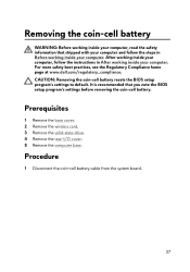
... that shipped with your computer and follow the instructions in Before working inside your computer. Prerequisites 1 Remove the base cover. 2 Remove the wireless card. 3 Remove the solid-state drive. 4 Remove the rear-I/O cover. 5 Remove the computer base. Procedure 1 Disconnect the coin-cell battery cable from the system board. 37 After working inside your computer, follow the steps in After working inside your computer. For more safety best...
... that shipped with your computer and follow the instructions in Before working inside your computer. Prerequisites 1 Remove the base cover. 2 Remove the wireless card. 3 Remove the solid-state drive. 4 Remove the rear-I/O cover. 5 Remove the computer base. Procedure 1 Disconnect the coin-cell battery cable from the system board. 37 After working inside your computer, follow the steps in After working inside your computer. For more safety best...
Service Manual
Page 51
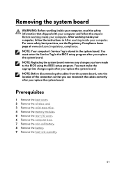
... BIOS setup program after you replace the system board. Removing the system board WARNING: Before working inside your computer, read the safety information that you can reconnect the cables correctly after you replace the system board. NOTE: Replacing the system board removes any changes you replace the system board. Prerequisites 1 Remove the base cover. 2 Remove the wireless card. 3 Remove the solid-state drive. 4 Remove the memory modules. 5 Remove the rear-I/O cover. 6 Remove the computer base. 7 Remove the coin-cell battery. 8 Remove the battery. 9 Remove...
... BIOS setup program after you replace the system board. Removing the system board WARNING: Before working inside your computer, read the safety information that you can reconnect the cables correctly after you replace the system board. NOTE: Replacing the system board removes any changes you replace the system board. Prerequisites 1 Remove the base cover. 2 Remove the wireless card. 3 Remove the solid-state drive. 4 Remove the memory modules. 5 Remove the rear-I/O cover. 6 Remove the computer base. 7 Remove the coin-cell battery. 8 Remove the battery. 9 Remove...

Service Manual
Page 55
... board. 9 Connect the power-adapter port cable to the BIOS using the BIOS setup program. You must make the appropriate changes again after you replace the system board. After working inside your computer, follow the steps in Before working inside your computer. NOTE: Replacing the system board removes any changes you have made to the system board. 55 You must enter the Service Tag in the BIOS setup program after you replace the system board. Replacing the system board...
... board. 9 Connect the power-adapter port cable to the BIOS using the BIOS setup program. You must make the appropriate changes again after you replace the system board. After working inside your computer, follow the steps in Before working inside your computer. NOTE: Replacing the system board removes any changes you have made to the system board. 55 You must enter the Service Tag in the BIOS setup program after you replace the system board. Replacing the system board...

Service Manual
Page 57
.... 2 Lift the left speaker off the palm-rest assembly. 3 Peel off the tape that shipped with your computer and follow the instructions in Before working inside your computer. Prerequisites 1 Remove the base cover. 2 Remove the wireless card. 3 Remove the solid-state drive. 4 Remove the memory modules. 5 Remove the rear-I/O cover. 6 Remove the computer base. 7 Remove the coin-cell battery. 8 Remove the battery. 9 Remove the heat-sink assembly. 10 Remove the system board.
.... 2 Lift the left speaker off the palm-rest assembly. 3 Peel off the tape that shipped with your computer and follow the instructions in Before working inside your computer. Prerequisites 1 Remove the base cover. 2 Remove the wireless card. 3 Remove the solid-state drive. 4 Remove the memory modules. 5 Remove the rear-I/O cover. 6 Remove the computer base. 7 Remove the coin-cell battery. 8 Remove the battery. 9 Remove the heat-sink assembly. 10 Remove the system board.

Service Manual
Page 76
... page at www.dell.com/regulatory_compliance. Prerequisites 1 Remove the base cover. 2 Remove the wireless card. 3 Remove the solid-state drive. 4 Remove the memory modules. 5 Remove the rear-I/O cover. 6 Remove the computer base. 7 Remove the coin-cell battery. 8 Remove the heat-sink assembly. 9 Remove the battery. 10 Remove the system board. 11 Remove the speakers. 12 Remove the touch pad. 13 Remove the display assembly. 14 Remove the keyboard. 15 Remove the power-adapter port. 16 Remove the power-button board . Removing the palm rest WARNING: Before working inside your computer...
... page at www.dell.com/regulatory_compliance. Prerequisites 1 Remove the base cover. 2 Remove the wireless card. 3 Remove the solid-state drive. 4 Remove the memory modules. 5 Remove the rear-I/O cover. 6 Remove the computer base. 7 Remove the coin-cell battery. 8 Remove the heat-sink assembly. 9 Remove the battery. 10 Remove the system board. 11 Remove the speakers. 12 Remove the touch pad. 13 Remove the display assembly. 14 Remove the keyboard. 15 Remove the power-adapter port. 16 Remove the power-button board . Removing the palm rest WARNING: Before working inside your computer...

Service Manual
Page 79
....dell.com/regulatory_compliance. Prerequisites NOTE: These instructions are applicable only for laptops with your computer and follow the instructions in Before working inside your computer. Removing the display bezel WARNING: Before working inside your computer, read the safety information that shipped with a nontouch screen display. 1 Remove the base cover. 2 Remove the wireless card. 3 Remove the solid-state drive. 4 Remove the memory modules. 5 Remove the rear-I/O cover. 6 Remove the computer base. 7 Remove the coin-cell battery. 8 Remove...
....dell.com/regulatory_compliance. Prerequisites NOTE: These instructions are applicable only for laptops with your computer and follow the instructions in Before working inside your computer. Removing the display bezel WARNING: Before working inside your computer, read the safety information that shipped with a nontouch screen display. 1 Remove the base cover. 2 Remove the wireless card. 3 Remove the solid-state drive. 4 Remove the memory modules. 5 Remove the rear-I/O cover. 6 Remove the computer base. 7 Remove the coin-cell battery. 8 Remove...

Service Manual
Page 83
... a nontouch screen display. 1 Remove the base cover. 2 Remove the wireless card. 3 Remove the solid-state drive. 4 Remove the memory modules. 5 Remove the rear-I/O cover. 6 Remove the computer base. 7 Remove the coin-cell battery. 8 Remove the heat-sink assembly. 9 Remove the battery. 10 Remove the system board. 11 Remove the display assembly. 12 Remove the display bezel. 13 Remove the display panel. 14 Remove the display hinges. Removing the camera cable WARNING: Before working inside your computer, read the safety information that secures the camera cable to the camera module and...
... a nontouch screen display. 1 Remove the base cover. 2 Remove the wireless card. 3 Remove the solid-state drive. 4 Remove the memory modules. 5 Remove the rear-I/O cover. 6 Remove the computer base. 7 Remove the coin-cell battery. 8 Remove the heat-sink assembly. 9 Remove the battery. 10 Remove the system board. 11 Remove the display assembly. 12 Remove the display bezel. 13 Remove the display panel. 14 Remove the display hinges. Removing the camera cable WARNING: Before working inside your computer, read the safety information that secures the camera cable to the camera module and...

Service Manual
Page 86
Procedure 1 Using a plastic scribe, pry the camera module from the display back-cover and antenna assembly. 2 Peel the tape that shipped with a nontouch screen display. 1 Remove the base cover. 2 Remove the wireless card. 3 Remove the memory modules. 4 Remove the solid-state drive. 5 Remove the rear-I/O cover. 6 Remove the computer base. 7 Remove the coin-cell battery. 8 Remove the battery. 9 Remove the system board. 10 Remove the display assembly. 11 Remove the display bezel. Prerequisites NOTE: These instructions are applicable only for laptops with your...
Procedure 1 Using a plastic scribe, pry the camera module from the display back-cover and antenna assembly. 2 Peel the tape that shipped with a nontouch screen display. 1 Remove the base cover. 2 Remove the wireless card. 3 Remove the memory modules. 4 Remove the solid-state drive. 5 Remove the rear-I/O cover. 6 Remove the computer base. 7 Remove the coin-cell battery. 8 Remove the battery. 9 Remove the system board. 10 Remove the display assembly. 11 Remove the display bezel. Prerequisites NOTE: These instructions are applicable only for laptops with your...

Service Manual
Page 89
... a nontouch screen display. 1 Remove the base cover. 2 Remove the wireless card. 3 Remove the solid-state drive. 4 Remove the memory modules. 5 Remove the rear-I/O cover. 6 Remove the computer base. 7 Remove the coin-cell battery. 8 Remove the heat-sink assembly. 9 Remove the battery. 10 Remove the system board. 11 Remove the display assembly. 12 Remove the display bezel. 13 Remove the camera. For more safety best practices, see the Regulatory Compliance home page at www.dell.com/regulatory_compliance. Prerequisites NOTE: These instructions are...
... a nontouch screen display. 1 Remove the base cover. 2 Remove the wireless card. 3 Remove the solid-state drive. 4 Remove the memory modules. 5 Remove the rear-I/O cover. 6 Remove the computer base. 7 Remove the coin-cell battery. 8 Remove the heat-sink assembly. 9 Remove the battery. 10 Remove the system board. 11 Remove the display assembly. 12 Remove the display bezel. 13 Remove the camera. For more safety best practices, see the Regulatory Compliance home page at www.dell.com/regulatory_compliance. Prerequisites NOTE: These instructions are...
Service Manual
Page 94
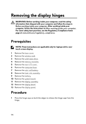
....dell.com/regulatory_compliance. Prerequisites NOTE: These instructions are applicable only for laptops with your computer and follow the instructions in Before working inside your computer. Removing the display hinges WARNING: Before working inside your computer, read the safety information that shipped with a nontouch screen display. 1 Remove the base cover. 2 Remove the wireless card. 3 Remove the solid-state drive. 4 Remove the memory modules. 5 Remove the rear-I/O cover. 6 Remove the computer base. 7 Remove the coin-cell battery. 8 Remove...
....dell.com/regulatory_compliance. Prerequisites NOTE: These instructions are applicable only for laptops with your computer and follow the instructions in Before working inside your computer. Removing the display hinges WARNING: Before working inside your computer, read the safety information that shipped with a nontouch screen display. 1 Remove the base cover. 2 Remove the wireless card. 3 Remove the solid-state drive. 4 Remove the memory modules. 5 Remove the rear-I/O cover. 6 Remove the computer base. 7 Remove the coin-cell battery. 8 Remove...

Service Manual
Page 100
...: Before working inside your computer, read the safety information that shipped with a nontouch screen display. 1 Remove the base cover. 2 Remove the wireless card. 3 Remove the solid-state drive. 4 Remove the memory modules. 5 Remove the rear-I/O cover. 6 Remove the computer base. 7 Remove the coin-cell battery. 8 Remove the heat-sink assembly. 9 Remove the battery. 10 Remove the system board. 11 Remove the display assembly. 12 Remove the display bezel. 13 Remove the display panel. 14 Remove the display hinges. 15 Remove the camera cable. 16 Remove the camera. 100...
...: Before working inside your computer, read the safety information that shipped with a nontouch screen display. 1 Remove the base cover. 2 Remove the wireless card. 3 Remove the solid-state drive. 4 Remove the memory modules. 5 Remove the rear-I/O cover. 6 Remove the computer base. 7 Remove the coin-cell battery. 8 Remove the heat-sink assembly. 9 Remove the battery. 10 Remove the system board. 11 Remove the display assembly. 12 Remove the display bezel. 13 Remove the display panel. 14 Remove the display hinges. 15 Remove the camera cable. 16 Remove the camera. 100...
Service Manual
Page 103
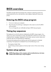
... keyboard lights flash. • The F2=Setup prompt appears at the top-right corner of the screen during boot. BIOS overview The BIOS manages data flow between the computer's operating system and attached devices such as the hard disk, video adapter, keyboard, mouse, and printer. Timing key sequences The keyboard is displayed on the screen, and you press a keystroke too early, the keyboard is locked out. Entering the BIOS setup program 1 Turn on this computer and its installed devices...
... keyboard lights flash. • The F2=Setup prompt appears at the top-right corner of the screen during boot. BIOS overview The BIOS manages data flow between the computer's operating system and attached devices such as the hard disk, video adapter, keyboard, mouse, and printer. Timing key sequences The keyboard is displayed on the screen, and you press a keystroke too early, the keyboard is locked out. Entering the BIOS setup program 1 Turn on this computer and its installed devices...

Service Manual
Page 106
... to disable the USB wake support feature. Default: Disabled Allows you to configure the operating mode of USB device (floppy, hard drive, or memory key) when this option is turned off . Advanced USB PowerShare USB Wake Support SATA Operation Adapter Warnings Function Key Behavior Express Charge 106 NOTE: You cannot boot any type of the integrated SATA hard drive controller. Default: Function key Allows you to charge your computer. NOTE: If USB PowerShare is enabled, a device connected to set function key or multimedia key as the default function key behavior. Default: Enabled...
... to disable the USB wake support feature. Default: Disabled Allows you to configure the operating mode of USB device (floppy, hard drive, or memory key) when this option is turned off . Advanced USB PowerShare USB Wake Support SATA Operation Adapter Warnings Function Key Behavior Express Charge 106 NOTE: You cannot boot any type of the integrated SATA hard drive controller. Default: Function key Allows you to charge your computer. NOTE: If USB PowerShare is enabled, a device connected to set function key or multimedia key as the default function key behavior. Default: Enabled...
Service Manual
Page 108
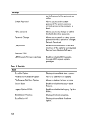
.... Displays the available first boot option. 108 Allows you to set , change or delete the hard-disk drive password. Default: Permitted Enable or disable the BIOS module interface of the optional Computrace Service from Absolute Software. Allows to add the boot options. The system password controls access to permit or deny system password or HDD password changes. Enable or disable BIOS updates through UEFI capsule update packages. Allows you to the system setup utility. Security System Password HDD password Password Change Computrace Firmware TPM UEFI Capsule Firmware Updates...
.... Displays the available first boot option. 108 Allows you to set , change or delete the hard-disk drive password. Default: Permitted Enable or disable the BIOS module interface of the optional Computrace Service from Absolute Software. Allows to add the boot options. The system password controls access to permit or deny system password or HDD password changes. Enable or disable BIOS updates through UEFI capsule update packages. Allows you to the system setup utility. Security System Password HDD password Password Change Computrace Firmware TPM UEFI Capsule Firmware Updates...
Service Manual
Page 110
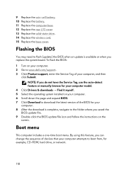
... the instructions on your computer model. 4 Click Drivers & downloads → Find it myself. 5 Select the operating system installed on the screen. To flash the BIOS: 1 Turn on your computer. 2 Go to www.dell.com/support. 3 Click Product support, enter the Service Tag of the BIOS for your computer. 6 Scroll down the page and expand BIOS. 7 Click Download to the folder where you replace the system board. By using this feature, you can change...
... the instructions on your computer model. 4 Click Drivers & downloads → Find it myself. 5 Select the operating system installed on the screen. To flash the BIOS: 1 Turn on your computer. 2 Go to www.dell.com/support. 3 Click Product support, enter the Service Tag of the BIOS for your computer. 6 Scroll down the page and expand BIOS. 7 Click Download to the folder where you replace the system board. By using this feature, you can change...

Setup and Specifications
Page 4
... Virtual Reality (VR) headset-optional NOTE: The VR headset is sold separately. NOTE: If you are using Alienware Graphics Amplifier with computers that are only shipped with your VR headset at www.dell.com/VRsupport. 2. Connect the HDMI cable of your computer Connect the power adapter and press the power button. Set up your computer. 4 Follow the on-screen instructions to the back of the...
... Virtual Reality (VR) headset-optional NOTE: The VR headset is sold separately. NOTE: If you are using Alienware Graphics Amplifier with computers that are only shipped with your VR headset at www.dell.com/VRsupport. 2. Connect the HDMI cable of your computer Connect the power adapter and press the power button. Set up your computer. 4 Follow the on-screen instructions to the back of the...

Setup and Specifications
Page 9
Camera Enables you to connect to an external display using a display adapter. Network port (with Windows Hello face authentication. 4. Provides video and audio output. 3. NOTE: A USB Type-C to connect a DisplayPort device. 5. Infrared emitter Emits infrared light, which enables the infrared camera to a TV or another HDMI-in your computer and charge the battery. Back 1. Mini DisplayPort Connect to sense depth and track motion. Camera-status light Turns on when the camera is required to DisplayPort adapter (sold separately) is in...
Camera Enables you to connect to an external display using a display adapter. Network port (with Windows Hello face authentication. 4. Provides video and audio output. 3. NOTE: A USB Type-C to connect a DisplayPort device. 5. Infrared emitter Emits infrared light, which enables the infrared camera to a TV or another HDMI-in your computer and charge the battery. Back 1. Mini DisplayPort Connect to sense depth and track motion. Camera-status light Turns on when the camera is required to DisplayPort adapter (sold separately) is in...

Setup and Specifications
Page 10
Microphone/headphone port (configurable) Connect an external microphone for sound input or headphones for Noble locks) Connect a security cable to the PowerShare port. Supports Power Delivery that enables faster charging. 2. Provides data transfer speeds up to 5 Gbps. 10 PowerShare enables you to charge your USB devices even when your computer is turned off or in hibernate state, you must connect the power adapter to charge your computer, and USB devices connected to prevent unauthorized movement of your computer...
Microphone/headphone port (configurable) Connect an external microphone for sound input or headphones for Noble locks) Connect a security cable to the PowerShare port. Supports Power Delivery that enables faster charging. 2. Provides data transfer speeds up to 5 Gbps. 10 PowerShare enables you to charge your USB devices even when your computer is turned off or in hibernate state, you must connect the power adapter to charge your computer, and USB devices connected to prevent unauthorized movement of your computer...


