Information Update - Processor Installation
Page 4
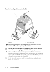
... lever can spring up suddenly if not firmly grasped. 9 Position your Hardware Owner's Manual for a system-specific illustration. See your thumb firmly over the processor socket-release lever and release the lever from the locked position by pushing down and pulling out from the...
... lever can spring up suddenly if not firmly grasped. 9 Position your Hardware Owner's Manual for a system-specific illustration. See your thumb firmly over the processor socket-release lever and release the lever from the locked position by pushing down and pulling out from the...
Information Update - Processor Installation
Page 5
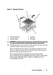
Do not touch the bottom of the pins on the ZIF socket when removing the processor. After removing the processor, place it in the CPU2 socket to installing a processor. Adding the blank is ready for reuse, return, or temporary storage. See "Installing a Processor". ...processor blank and a heat-sink blank in an antistatic container for the new processor. Removing a Processor 2 3 1 4 1 socket-release lever 3 processor shield 2 processor 4 ZIF socket CAUTION: Be careful not to bend any of the processor. Figure 1-2. Bending the pins can permanently damage the system board. 11...
Do not touch the bottom of the pins on the ZIF socket when removing the processor. After removing the processor, place it in the CPU2 socket to installing a processor. Adding the blank is ready for reuse, return, or temporary storage. See "Installing a Processor". ...processor blank and a heat-sink blank in an antistatic container for the new processor. Removing a Processor 2 3 1 4 1 socket-release lever 3 processor shield 2 processor 4 ZIF socket CAUTION: Be careful not to bend any of the processor. Figure 1-2. Bending the pins can permanently damage the system board. 11...
Information Update - Processor Installation
Page 6
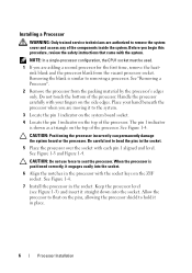
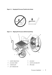
... the processor with each pin 1 aligned and level. Keep the processor level (see Figure 1-3) and insert it engages easily into the socket. The pin 1 indicator is similar to removing a processor. See Figure 1-3 and Figure 1-4. See "Removing a Processor". 2 Remove the processor from...board or the processor. When the processor is positioned correctly, it straight down into the socket. 6 Align the notches in the socket. 5 Place the processor over the socket with the socket keys on the ZIF socket. Place your fingers on the side edges. Be careful not to seat the processor. See...
... the processor with each pin 1 aligned and level. Keep the processor level (see Figure 1-3) and insert it engages easily into the socket. The pin 1 indicator is similar to removing a processor. See Figure 1-3 and Figure 1-4. See "Removing a Processor". 2 Remove the processor from...board or the processor. When the processor is positioned correctly, it straight down into the socket. 6 Align the notches in the socket. 5 Place the processor over the socket with the socket keys on the ZIF socket. Place your fingers on the side edges. Be careful not to seat the processor. See...
Information Update - Processor Installation
Page 7
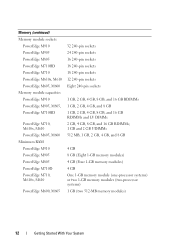
Figure 1-3. Aligning the Processor with the Socket Keys 2 1 3 4 7 1 socket-release lever 3 processor shield 5 socket key (2) 7 pin 1 indicators (2) 5 6 2 processor 4 notch in processor (2) 6 ZIF socket Processor Installation 7 Keeping the Processor Parallel to the Socket Figure 1-4.
Figure 1-3. Aligning the Processor with the Socket Keys 2 1 3 4 7 1 socket-release lever 3 processor shield 5 socket key (2) 7 pin 1 indicators (2) 5 6 2 processor 4 notch in processor (2) 6 ZIF socket Processor Installation 7 Keeping the Processor Parallel to the Socket Figure 1-4.
Information Update - Processor Installation
Page 8
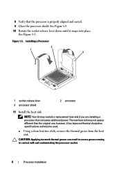
...thermal grease from the heat sink. CAUTION: Applying too much thermal grease can result in excess grease coming in contact with and contaminating the processor socket. 8 Processor Installation NOTE: Your kit may not appear different than the original one; The new heat sink may contain a replacement heat sink ... aligned and seated. 9 Close the processor shield. however, it snaps into place. 8 Verify that consumes additional power. See Figure 1-5. 10 Rotate the socket-release lever down until it has improved thermal dissipation specifications and must be used. See Figure 1-5.
...thermal grease from the heat sink. CAUTION: Applying too much thermal grease can result in excess grease coming in contact with and contaminating the processor socket. 8 Processor Installation NOTE: Your kit may not appear different than the original one; The new heat sink may contain a replacement heat sink ... aligned and seated. 9 Close the processor shield. however, it snaps into place. 8 Verify that consumes additional power. See Figure 1-5. 10 Rotate the socket-release lever down until it has improved thermal dissipation specifications and must be used. See Figure 1-5.
Getting Started Guide
Page 14
Memory (continued) Memory module sockets PowerEdge M910 PowerEdge M905 PowerEdge M805 PowerEdge M710HD PowerEdge M710 PowerEdge M610x, M610 PowerEdge M605, M600 Memory module capacities PowerEdge M910 PowerEdge M905, M805, PowerEdge ... PowerEdge M905 PowerEdge M805 PowerEdge M710D PowerEdge M710, M610x, M610 PowerEdge M600, M605 32 240-pin sockets 24 240-pin sockets 16 240-pin sockets 18 240-pin sockets 18 240-pin sockets 12 240-pin sockets Eight 240-pin sockets 1 GB, 2 GB, 4 GB, 8 GB, and 16 GB RDIMMs 1 GB, 2 GB, 4 GB, and 8 GB 1 GB, 2 GB, 4 GB...
Memory (continued) Memory module sockets PowerEdge M910 PowerEdge M905 PowerEdge M805 PowerEdge M710HD PowerEdge M710 PowerEdge M610x, M610 PowerEdge M605, M600 Memory module capacities PowerEdge M910 PowerEdge M905, M805, PowerEdge ... PowerEdge M905 PowerEdge M805 PowerEdge M710D PowerEdge M710, M610x, M610 PowerEdge M600, M605 32 240-pin sockets 24 240-pin sockets 16 240-pin sockets 18 240-pin sockets 18 240-pin sockets 12 240-pin sockets Eight 240-pin sockets 1 GB, 2 GB, 4 GB, 8 GB, and 16 GB RDIMMs 1 GB, 2 GB, 4 GB, and 8 GB 1 GB, 2 GB, 4 GB...
Hardware Owner's Manual
Page 112
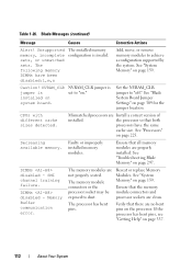
... Your System See "Troubleshooting Blade Memory" on system board. Memory Buffer communication error. The memory module connectors or the processor socket may be exposed to "on page 159. NVRAM_CLR jumper is invalid. Faulty or improperly installed memory modules. Ensure that both ...processors have been disabled:l,m,n The installed memory configuration is installed on page 297. Verify that the memory module connectors and processor sockets are no bent pins on the processor. See "Processors" on page 309 for the jumper location. Reseat or replace ...
... Your System See "Troubleshooting Blade Memory" on system board. Memory Buffer communication error. The memory module connectors or the processor socket may be exposed to "on page 159. NVRAM_CLR jumper is invalid. Faulty or improperly installed memory modules. Ensure that both ...processors have been disabled:l,m,n The installed memory configuration is installed on page 297. Verify that the memory module connectors and processor sockets are no bent pins on the processor. See "Processors" on page 309 for the jumper location. Reseat or replace ...
Hardware Owner's Manual
Page 134
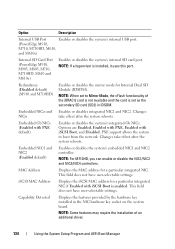
NOTE: When set as the secondary SD card (SD2) in the NIC hardware key socket on the system board. Embedded NICn and Enables or disables integrated NIC1 and NIC2. Embedded Gb NICx (Enabled with iSCSI Boot is enabled. Embedded NIC1 ...
NOTE: When set as the secondary SD card (SD2) in the NIC hardware key socket on the system board. Embedded NICn and Enables or disables integrated NIC1 and NIC2. Embedded Gb NICx (Enabled with iSCSI Boot is enabled. Embedded NIC1 ...
Hardware Owner's Manual
Page 159
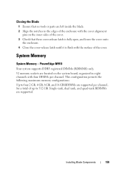
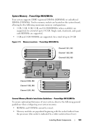
... 159 Single-rank, dual rank, and quad-rank RDIMMs are supported per channel. PowerEdge M910 Your system supports DDR3 registered DIMMs (RDIMMS) only. 32 memory sockets are located on the system board, organized in the edges of the enclosure with the cover alignment pins on the inner sides of the cover...
... 159 Single-rank, dual rank, and quad-rank RDIMMs are supported per channel. PowerEdge M910 Your system supports DDR3 registered DIMMs (RDIMMS) only. 32 memory sockets are located on the system board, organized in the edges of the enclosure with the cover alignment pins on the inner sides of the cover...
Hardware Owner's Manual
Page 161
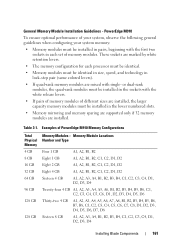
...GB A1, A2, A3, A4, B1, B2, B3, B4, C1, C2, C3, C4, D1, D2, D3, D4 Installing Blade Components 161 These sockets are marked by white retention levers. • The memory configuration for each processor must be identical. • Memory modules must be installed in pairs, beginning... with the first two sockets in each set of your system, observe the following general guidelines when configuring your system memory: • Memory modules must be identical in ...
...GB A1, A2, A3, A4, B1, B2, B3, B4, C1, C2, C3, C4, D1, D2, D3, D4 Installing Blade Components 161 These sockets are marked by white retention levers. • The memory configuration for each processor must be identical. • Memory modules must be installed in pairs, beginning... with the first two sockets in each set of your system, observe the following general guidelines when configuring your system memory: • Memory modules must be identical in ...

Hardware Owner's Manual
Page 164
... B8 DD32 D4 C1 C2 A8 C3 C4 A1 General Memory Module Installation Guidelines - PowerEdge M905 To ensure optimal performance of memory modules. These sockets are marked by white retention levers. • All memory modules in each pair must be installed in pairs, beginning with the first two... sockets in the blade must be the same size. 164 Installing Blade Components Memory Locations - Figure 3-13. The memory modules in each set of your ...
... B8 DD32 D4 C1 C2 A8 C3 C4 A1 General Memory Module Installation Guidelines - PowerEdge M905 To ensure optimal performance of memory modules. These sockets are marked by white retention levers. • All memory modules in each pair must be installed in pairs, beginning with the first two... sockets in the blade must be the same size. 164 Installing Blade Components Memory Locations - Figure 3-13. The memory modules in each set of your ...
Hardware Owner's Manual
Page 165
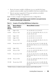
... supported memory configurations. • If pairs of memory modules of different sizes are installed, the larger capacity memory modules must be installed in unoccupied memory sockets to maintain proper cooling airflow. Installing Blade Components 165 Table 3-3.
... supported memory configurations. • If pairs of memory modules of different sizes are installed, the larger capacity memory modules must be installed in unoccupied memory sockets to maintain proper cooling airflow. Installing Blade Components 165 Table 3-3.

Hardware Owner's Manual
Page 168
...) for both processors. • If pairs of memory modules of different sizes are installed, the larger capacity memory modules must be installed in unoccupied memory sockets to maintain proper cooling airflow.
...) for both processors. • If pairs of memory modules of different sizes are installed, the larger capacity memory modules must be installed in unoccupied memory sockets to maintain proper cooling airflow.
Hardware Owner's Manual
Page 170
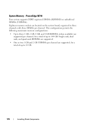
... DIMMs per channel, for a total of up to 144 GB. PowerEdge M710 Your system supports DDR3 registered DIMMs (RDIMMS) or unbuffered DIMMs (UDIMMs). Eighteen memory sockets are supported per channel.
... DIMMs per channel, for a total of up to 144 GB. PowerEdge M710 Your system supports DDR3 registered DIMMs (RDIMMS) or unbuffered DIMMs (UDIMMs). Eighteen memory sockets are supported per channel.
Hardware Owner's Manual
Page 172
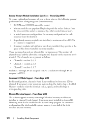
...channel is one 128-bit channel. Mirroring must also be identical in size, speed, and technology in channel 0 and channel 1 (memory is disabled. sockets 3, 6, 9 • Channel 1 - If a memory error occurs on the memory mode selected. In a mirrored configuration, the total available system... modules with different speeds are assigned to each processor must be enabled in channel 2). Three memory channels are populated beginning with the socket farthest from the processor (this configuration, channels 0 and 1 are combined to CPU2. Memory modules must be mixed. • ...
...channel is one 128-bit channel. Mirroring must also be identical in size, speed, and technology in channel 0 and channel 1 (memory is disabled. sockets 3, 6, 9 • Channel 1 - If a memory error occurs on the memory mode selected. In a mirrored configuration, the total available system... modules with different speeds are assigned to each processor must be enabled in channel 2). Three memory channels are populated beginning with the socket farthest from the processor (this configuration, channels 0 and 1 are combined to CPU2. Memory modules must be mixed. • ...

Hardware Owner's Manual
Page 176
Eighteen memory sockets are supported. This configuration supports up to three 2 GB, 4 GB, 8 GB and up to two16 GB RDIMMs per channel. Memory Locations - PowerEdge M710HD A1 A4 ...
Eighteen memory sockets are supported. This configuration supports up to three 2 GB, 4 GB, 8 GB and up to two16 GB RDIMMs per channel. Memory Locations - PowerEdge M710HD A1 A4 ...
Hardware Owner's Manual
Page 177
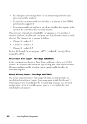
... 0 and channel 1 (memory is disabled. Mirroring must be identical in size, speed, and technology in corresponding slots. Installing Blade Components 177 sockets 3, 6, 9 • Channel 1 - If a memory error occurs on the memory mode selected. Memory Mirroring Support - Three DDR3 memory channels... are assigned to form one -half of the total installed physical memory. sockets 1, 4, 7 Sockets A1 through B9 are allocated to CPU1; The channels are assigned to each processor must be enabled in channel 2). Advanced ...
... 0 and channel 1 (memory is disabled. Mirroring must be identical in size, speed, and technology in corresponding slots. Installing Blade Components 177 sockets 3, 6, 9 • Channel 1 - If a memory error occurs on the memory mode selected. Memory Mirroring Support - Three DDR3 memory channels... are assigned to form one -half of the total installed physical memory. sockets 1, 4, 7 Sockets A1 through B9 are allocated to CPU1; The channels are assigned to each processor must be enabled in channel 2). Advanced ...
Hardware Owner's Manual
Page 181
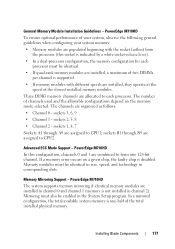
...a total of up to 192 GB. PowerEdge M610/M610x Your system supports DDR3 registered DIMMs (RDIMMS) or unbuffered DIMMs (UDIMMs). Twelve memory sockets are located on the system board, allowing for the following general guidelines when configuring your system memory: • RDIMMs and UDIMMs cannot be... memory configurations: • 1 GB, 2 GB, 4 GB, 8 GB, and 16 GB RDIMMs (when available) are populated beginning with the socket farthest from the processor (this socket is indicated by a white socket-release lever). PowerEdge M610//M610x To ensure optimal performance of up to 24 GB.
...a total of up to 192 GB. PowerEdge M610/M610x Your system supports DDR3 registered DIMMs (RDIMMS) or unbuffered DIMMs (UDIMMs). Twelve memory sockets are located on the system board, allowing for the following general guidelines when configuring your system memory: • RDIMMs and UDIMMs cannot be... memory configurations: • 1 GB, 2 GB, 4 GB, 8 GB, and 16 GB RDIMMs (when available) are populated beginning with the socket farthest from the processor (this socket is indicated by a white socket-release lever). PowerEdge M610//M610x To ensure optimal performance of up to 24 GB.
Hardware Owner's Manual
Page 182
The channels are assigned to each processor must also be enabled in the System Setup program. sockets 1, 4 Sockets A1 through B6 are allocated to CPU1; If a memory error occurs on the memory mode selected. Memory Mirroring Support...processor configuration, the memory configuration for each processor. The number of the total installed physical memory. 182 Installing Blade Components sockets B1 through A6 are organized as follows: • Channel 0 - sockets 3, 6 • Channel 1 - Memory modules must be identical in size, speed, and technology in corresponding slots...
The channels are assigned to each processor must also be enabled in the System Setup program. sockets 1, 4 Sockets A1 through B6 are allocated to CPU1; If a memory error occurs on the memory mode selected. Memory Mirroring Support...processor configuration, the memory configuration for each processor. The number of the total installed physical memory. 182 Installing Blade Components sockets B1 through A6 are organized as follows: • Channel 0 - sockets 3, 6 • Channel 1 - Memory modules must be identical in size, speed, and technology in corresponding slots...
Hardware Owner's Manual
Page 187
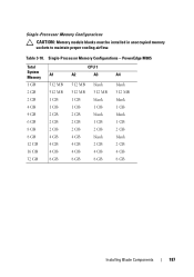
Single-Processor Memory Configurations CAUTION: Memory module blanks must be installed in unoccupied memory sockets to maintain proper cooling airflow. Table 3-10. Single-Processor Memory Configurations - PowerEdge M605 Total System Memory 1 GB 2 GB 2 GB 4 GB 4 GB 6 GB 8 GB 8 GB 12 ...
Single-Processor Memory Configurations CAUTION: Memory module blanks must be installed in unoccupied memory sockets to maintain proper cooling airflow. Table 3-10. Single-Processor Memory Configurations - PowerEdge M605 Total System Memory 1 GB 2 GB 2 GB 4 GB 4 GB 6 GB 8 GB 8 GB 12 ...
