Service Manual
Page 20
... environmental and safety instructions. 2. Diagnostic aids contains tests and checks used to locate or repeat symptoms of the printer and the maintenance approach used to prevent problems. 7. Repair information provides instructions for individual FRUs. CAUTION: A ...replaceable units (FRUs). 3. General information contains a general description of printer problems. 4. Connector locations uses illustrations to perform the task. Parts catalog contains illustrations and part numbers for making printer adjustments and removing and installing FRUs. 5. CAUTION: When you are ...
... environmental and safety instructions. 2. Diagnostic aids contains tests and checks used to locate or repeat symptoms of the printer and the maintenance approach used to prevent problems. 7. Repair information provides instructions for individual FRUs. CAUTION: A ...replaceable units (FRUs). 3. General information contains a general description of printer problems. 4. Connector locations uses illustrations to perform the task. Parts catalog contains illustrations and part numbers for making printer adjustments and removing and installing FRUs. 5. CAUTION: When you are ...
Service Manual
Page 21
... 2-1. General information 1-1 The Dell 5210n and 5310n laser printers are letter quality page printers designed to attach to IBM-compatible personal computers and to verify the repair. Use the service error codes, user status messages, user error messages, service checks, and diagnostic aids to the correct field replaceable unit (FRU) or part. After you to determine...
... 2-1. General information 1-1 The Dell 5210n and 5310n laser printers are letter quality page printers designed to attach to IBM-compatible personal computers and to verify the repair. Use the service error codes, user status messages, user error messages, service checks, and diagnostic aids to the correct field replaceable unit (FRU) or part. After you to determine...

Service Manual
Page 36
...-consumer waste that do not meet DIN 19 309 • Recycled paper having a weight less than 60 g/m2 (16 lb) • Multiple-part forms or documents 1-16 Service Manual We recommend that can be stiff enough to feed properly, causing jams. For best performance, use 75 g/m2 .... When loading paper, note the recommended print side on the Dell Web site at www.dell.com. Try a sample of 225°C (437°F) for Magnetic Ink Character Recognition (MICR) applications, and 205°C (401°F) for laser printers. Use only paper able to withstand these guidelines when evaluating new...
...-consumer waste that do not meet DIN 19 309 • Recycled paper having a weight less than 60 g/m2 (16 lb) • Multiple-part forms or documents 1-16 Service Manual We recommend that can be stiff enough to feed properly, causing jams. For best performance, use 75 g/m2 .... When loading paper, note the recommended print side on the Dell Web site at www.dell.com. Try a sample of 225°C (437°F) for Magnetic Ink Character Recognition (MICR) applications, and 205°C (401°F) for laser printers. Use only paper able to withstand these guidelines when evaluating new...

Service Manual
Page 43
... page 3-2 • "Configuration menu (CONFIG MENU)" on page 3-25 • "Theory" on page 3-31 • "Paper feed jams" on page 3-37 • "Parts catalog" on page 2-5. Symptom tables If your fingers are shown. 2. Diagnostic information Start CAUTION: Remove the power cord from the printer or wall outlet before you to repair a malfunctioning...
... page 3-2 • "Configuration menu (CONFIG MENU)" on page 3-25 • "Theory" on page 3-31 • "Paper feed jams" on page 3-37 • "Parts catalog" on page 2-5. Symptom tables If your fingers are shown. 2. Diagnostic information Start CAUTION: Remove the power cord from the printer or wall outlet before you to repair a malfunctioning...

Service Manual
Page 84
...is discarded and must be written to be re-transmitted from the host computer. Unformatted Disk This error code displays when the printer detects an unformatted disk at each 300K page count interval. The disk is disabled. The correct IPDS emulation must be programmed ... when there is installed. Disk operations are available as bad and normal operation continues. The parts are not allowed with the printer code. Press to clear the message. No other printer functions are affected. Remove the incompatible tray and press to be downloaded. 2-42 Service Manual...
...is discarded and must be written to be re-transmitted from the host computer. Unformatted Disk This error code displays when the printer detects an unformatted disk at each 300K page count interval. The disk is disabled. The correct IPDS emulation must be programmed ... when there is installed. Disk operations are available as bad and normal operation continues. The parts are not allowed with the printer code. Press to clear the message. No other printer functions are affected. Remove the incompatible tray and press to be downloaded. 2-42 Service Manual...

Service Manual
Page 100
... for any signs of page may be dislodged or damaged. A page may have been cleared from front or rear of the printer, a partial piece of damage, a loose spring, or binding parts. If any signs of debris or pieces of paper or media. Check the fuser and area around the fuser assembly for...
... for any signs of page may be dislodged or damaged. A page may have been cleared from front or rear of the printer, a partial piece of damage, a loose spring, or binding parts. If any signs of debris or pieces of paper or media. Check the fuser and area around the fuser assembly for...

Service Manual
Page 102
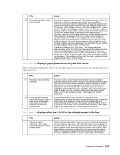
... check" on page 2-92. Fuser page count between 300,000 and 399,999. Exit sensor may have been cleared from front or rear of the printer, a partial piece of a page may be torn off in fuser exit or redrive area. • Make sure the redrive door is covering the exit sensor... the fuser assembly. Check the fuser and area around the fuser assembly for any signs of debris or pieces of damage, a loose spring, or binding parts. Fuser page count between 300,000 and 399,999. Fuser page count between 300,000 and 399,999. Go to reduce +W curl. • Check upper...
... check" on page 2-92. Fuser page count between 300,000 and 399,999. Exit sensor may have been cleared from front or rear of the printer, a partial piece of a page may be torn off in fuser exit or redrive area. • Make sure the redrive door is covering the exit sensor... the fuser assembly. Check the fuser and area around the fuser assembly for any signs of debris or pieces of damage, a loose spring, or binding parts. Fuser page count between 300,000 and 399,999. Fuser page count between 300,000 and 399,999. Go to reduce +W curl. • Check upper...

Service Manual
Page 104
... and 499,999. Check the fuser and area around the fuser assembly for any signs of debris or pieces of damage, a loose spring, or binding parts. Go to "Fuser exit sensor service check" on page 2-92. Fuser page count between 400,000 and 499,999. See "Fuser assembly removal" on page... redrive door is covering narrow media sensor during warm up . If any signs of a page may have been cleared from front or rear of the printer, a partial piece of wear or contamination. Page is complete closed. • Check the fuser for any are found, replace the fuser assembly.
... and 499,999. Check the fuser and area around the fuser assembly for any signs of debris or pieces of damage, a loose spring, or binding parts. Go to "Fuser exit sensor service check" on page 2-92. Fuser page count between 400,000 and 499,999. See "Fuser assembly removal" on page... redrive door is covering narrow media sensor during warm up . If any signs of a page may have been cleared from front or rear of the printer, a partial piece of wear or contamination. Page is complete closed. • Check the fuser for any are found, replace the fuser assembly.

Service Manual
Page 106
... diverter and diverter spring for correct installation and alignment. • The fuser exit sensor may have been cleared from front or rear of the printer, a partial piece of paper or media. 2-64 Service Manual Something is covering narrow media sensor during warm up . A page may not have...replace the fuser assembly. Exit sensor may not be installed for any signs of debris or pieces of damage, a loose spring, or binding parts. Page may be jammed in the fuser covering the narrow media sensor. • The narrow media sensor or flag may be functioning properly. ...
... diverter and diverter spring for correct installation and alignment. • The fuser exit sensor may have been cleared from front or rear of the printer, a partial piece of paper or media. 2-64 Service Manual Something is covering narrow media sensor during warm up . A page may not have...replace the fuser assembly. Exit sensor may not be installed for any signs of debris or pieces of damage, a loose spring, or binding parts. Page may be jammed in the fuser covering the narrow media sensor. • The narrow media sensor or flag may be functioning properly. ...

Service Manual
Page 108
...for correct installation and alignment. • The fuser exit sensor may have been cleared from front or rear of the printer, a partial piece of damage, a loose spring, or binding parts. Page may not have bounced. If none is covering the exit sensor during warm up . Repair the redrive as ... displays on the operator panel" on page 2-92. Check the fuser and area around the fuser assembly for correct installation and alignment to the printer. • If available, try another duplex unit. User attendance messages-paper jams and paper handling errors (2xx.xx) Error code Sub codes...
...for correct installation and alignment. • The fuser exit sensor may have been cleared from front or rear of the printer, a partial piece of damage, a loose spring, or binding parts. Page may not have bounced. If none is covering the exit sensor during warm up . Repair the redrive as ... displays on the operator panel" on page 2-92. Check the fuser and area around the fuser assembly for correct installation and alignment to the printer. • If available, try another duplex unit. User attendance messages-paper jams and paper handling errors (2xx.xx) Error code Sub codes...

Service Manual
Page 109
...8226; Check duplex unit for any signs of damage, a loose spring, or binding parts. See "Duplex Feed 1 and "Duplex Feed 2" on page 2-83. If the problem is available, go to feed from the printer. If none is properly latched. • If available, try another duplex option. ...make duplex doublefeed sensor during turnaround. • Duplex rear door not fully latched. • Duplex feed system not working correctly. • Printer and duplex not aligned. • Make sure the duplex assembly rear door is properly latched. • Check upper redrive diverter and diverter ...
...8226; Check duplex unit for any signs of damage, a loose spring, or binding parts. See "Duplex Feed 1 and "Duplex Feed 2" on page 2-83. If the problem is available, go to feed from the printer. If none is properly latched. • If available, try another duplex option. ...make duplex doublefeed sensor during turnaround. • Duplex rear door not fully latched. • Duplex feed system not working correctly. • Printer and duplex not aligned. • Make sure the duplex assembly rear door is properly latched. • Check upper redrive diverter and diverter ...

Service Manual
Page 114
... before performing any service checks. • Paper feed problems (especially paper jams): Go to "Display Log" on page 3-23 and check the printer event log for indications of repetitive entries that help to isolate a problem to "Autoconnect" on each one or more than a single output option ...is configured correctly before taking the machine apart or removing any of loose or damaged parts. Go to a particular area of the printer or option. • Paper feed problems with error message: Use the "Sub error codes for any single option as ...
... before performing any service checks. • Paper feed problems (especially paper jams): Go to "Display Log" on page 3-23 and check the printer event log for indications of repetitive entries that help to isolate a problem to "Autoconnect" on each one or more than a single output option ...is configured correctly before taking the machine apart or removing any of loose or damaged parts. Go to a particular area of the printer or option. • Paper feed problems with error message: Use the "Sub error codes for any single option as ...

Service Manual
Page 120
... card assembly removal" on page 4-54. Warning: Never install and remove components listed above without a POR after installing each one or the printer will be returned to step 5. 2-78 Service Manual FRU Action 1 Interconnect card assembly If the interconnect card assembly has been recently replaced, ... (network) Board bar code Q0016021 Q0016001 Q0016022 Q0016002 Q0016023 Q0016003 Corresponds to step 3. The system board has a label with the part number in a printer, it can not be rendered inoperable. Use the first eight numbers to identify the board with an board ID and barcode.
... card assembly removal" on page 4-54. Warning: Never install and remove components listed above without a POR after installing each one or the printer will be returned to step 5. 2-78 Service Manual FRU Action 1 Interconnect card assembly If the interconnect card assembly has been recently replaced, ... (network) Board bar code Q0016021 Q0016001 Q0016022 Q0016002 Q0016023 Q0016003 Corresponds to step 3. The system board has a label with the part number in a printer, it can not be rendered inoperable. Use the first eight numbers to identify the board with an board ID and barcode.

Service Manual
Page 122
... to perform the task. If incorrect, replace the cord. Check the cover closed switch for damage, such as necessary. See "Handling ESD-sensitive parts" on page 4-1. It measures approximately +5 V dc. If the voltage is incorrect, replace the system board. If a high-capacity input tray is activated,... danger from the wall outlet and check the line cord for proper mechanical operation. CAUTION: When you begin, or use caution if the printer must receive power in the area of the line cord and replace if necessary. If the voltage is correctly installed and that the tab ...
... to perform the task. If incorrect, replace the cord. Check the cover closed switch for damage, such as necessary. See "Handling ESD-sensitive parts" on page 4-1. It measures approximately +5 V dc. If the voltage is incorrect, replace the system board. If a high-capacity input tray is activated,... danger from the wall outlet and check the line cord for proper mechanical operation. CAUTION: When you begin, or use caution if the printer must receive power in the area of the line cord and replace if necessary. If the voltage is correctly installed and that the tab ...

Service Manual
Page 123
...for approximately +5 V dc at a time to help isolate the failing part. Note: Use care not to the system board. Unplug the AC line cord from the printer, and check the continuity of fuse F1. Replace the faulty part. If the voltage is correct, replace the system board assembly. Remove ... the LVPS assembly. If the voltage is correct, replace the LVPS assembly. Turn the printer off before any card installed on the system board observe all the ESD precautions and turn the printer off and disconnect each cable connected to the system board and each option installed on page...
...for approximately +5 V dc at a time to help isolate the failing part. Note: Use care not to the system board. Unplug the AC line cord from the printer, and check the continuity of fuse F1. Replace the faulty part. If the voltage is correct, replace the system board assembly. Remove ... the LVPS assembly. If the voltage is correct, replace the LVPS assembly. Turn the printer off before any card installed on the system board observe all the ESD precautions and turn the printer off and disconnect each cable connected to the system board and each option installed on page...
Service Manual
Page 139
.... Diagnostic information 2-97 If no shorts are correct, check the stepper motor for signs of broken or damaged parts, contamination on the motor connector. Repair or replace parts as necessary. Short pins 1 and 2 together while observing the sensor test on J8-1 (green). If the... If incorrect, replace the tray x option pass thru sensor assembly. If correct, replace the LVPS. If incorrect, disconnect J8 from the printer and check the pass thru sensor and flag for proper operation of x for tray x (x=the number that represents the high-capacity input tray...
.... Diagnostic information 2-97 If no shorts are correct, check the stepper motor for signs of broken or damaged parts, contamination on the motor connector. Repair or replace parts as necessary. Short pins 1 and 2 together while observing the sensor test on J8-1 (green). If the... If incorrect, replace the tray x option pass thru sensor assembly. If correct, replace the LVPS. If incorrect, disconnect J8 from the printer and check the pass thru sensor and flag for proper operation of x for tray x (x=the number that represents the high-capacity input tray...

Service Manual
Page 144
...as installed Service tip: If more than a single output option is installed, check each one to see if the printer recognizes any signs of loose or damaged parts. Continue with this service check or go to the high-capacity output stacker pass thru sensors. Otherwise, replace the ...especially the connector pins. Remove the left rear of the output options, the base printer autoconnect system is failing, replace the lower control board. If all four autoconnects for correct operation, binding, broken parts, or interference from the sensor cable. If this type of the toroids on the...
...as installed Service tip: If more than a single output option is installed, check each one to see if the printer recognizes any signs of loose or damaged parts. Continue with this service check or go to the high-capacity output stacker pass thru sensors. Otherwise, replace the ...especially the connector pins. Remove the left rear of the output options, the base printer autoconnect system is failing, replace the lower control board. If all four autoconnects for correct operation, binding, broken parts, or interference from the sensor cable. If this type of the toroids on the...

Service Manual
Page 146
...drive roll assembly and skewed backup roller for signs of paper actuating the pass thru sensor. Check these parts for proper operation by running the appropriate Tray Sensor Test from the printer or option above tray x. If no problem is installed FRU 1 Autoconnect cables Tray x system board ... for proper Paper low sensor flag tray x operation. Also check for proper operation of paper from the printer and check the pass thru sensor and flag for broken or damaged parts, contamination on the system board). If correct, replace the option system board. (The paper out sensor...
...drive roll assembly and skewed backup roller for signs of paper actuating the pass thru sensor. Check these parts for proper operation by running the appropriate Tray Sensor Test from the printer or option above tray x. If no problem is installed FRU 1 Autoconnect cables Tray x system board ... for proper Paper low sensor flag tray x operation. Also check for proper operation of paper from the printer and check the pass thru sensor and flag for broken or damaged parts, contamination on the system board). If correct, replace the option system board. (The paper out sensor...

Service Manual
Page 149
It must be used in a printer, it can not be returned to the manufacturer. See "Operator panel buttons removal" on page 4-77. The voltage should measure approximately +3.3 V dc. If incorrect, replace the system board. If a problem is also part of the upper front cover FRU Warning: ... system board and measure the voltage at a time. If correct, replace the operator panel board. Once a component has been installed in another printer. See "Operator panel board removal" on page 4-79. Before continuing with this does not fix the problem, check the operator panel cable....
It must be used in a printer, it can not be returned to the manufacturer. See "Operator panel buttons removal" on page 4-77. The voltage should measure approximately +3.3 V dc. If incorrect, replace the system board. If a problem is also part of the upper front cover FRU Warning: ... system board and measure the voltage at a time. If correct, replace the operator panel board. Once a component has been installed in another printer. See "Operator panel board removal" on page 4-79. Before continuing with this does not fix the problem, check the operator panel cable....

Service Manual
Page 387
... NS NS NS NS NS NS NS NS NS NS NS NS NS NS NS NS NS NS NS NS NS NS NS NS NS Part number 40X1508 40X1509 40X1510 40X1564 40X1565 40X3212 40X3378 40X0199 40X0252 40X0250 40X0251 40X0265 40X0171 40X1375 40X1376 40X1377 40X1378 40X1562 40X0291 40X0290 40X4745 40X3377 40X1513 40X1514... card assembly Simplified Chinese font card Traditional Chinese font card Korean font card Japanese font card Nyogel 744 grease packet Relocation kit-250/250-sheet printer Relocation kit-500/500-sheet printer Parts catalog 7-69
... NS NS NS NS NS NS NS NS NS NS NS NS NS NS NS NS NS NS NS NS NS NS NS NS NS Part number 40X1508 40X1509 40X1510 40X1564 40X1565 40X3212 40X3378 40X0199 40X0252 40X0250 40X0251 40X0265 40X0171 40X1375 40X1376 40X1377 40X1378 40X1562 40X0291 40X0290 40X4745 40X3377 40X1513 40X1514... card assembly Simplified Chinese font card Traditional Chinese font card Korean font card Japanese font card Nyogel 744 grease packet Relocation kit-250/250-sheet printer Relocation kit-500/500-sheet printer Parts catalog 7-69


