
Service Manual
Page 2
... damage to hardware or loss of Dell Inc. Microsoft®, Windows®, and the Windows start button logo are not followed. Trademarks used in this document to refer to change without the written permission of data if instructions are either the entities claiming the marks and names or their products. Dell Inc. Regulatory model: P17F Regulatory type: P17F001 2011 - 02 Rev. A00...
... damage to hardware or loss of Dell Inc. Microsoft®, Windows®, and the Windows start button logo are not followed. Trademarks used in this document to refer to change without the written permission of data if instructions are either the entities claiming the marks and names or their products. Dell Inc. Regulatory model: P17F Regulatory type: P17F001 2011 - 02 Rev. A00...
Service Manual
Page 9
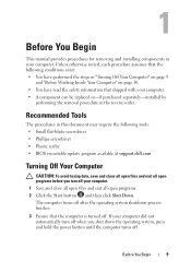
...operating system, press and hold the power button until the computer turns off. The computer turns off . Recommended Tools The procedures in this document may require the following conditions exist: • You have performed the steps in the reverse order. 1 Before You Begin This manual provides procedures for removing and installing...; Plastic scribe • BIOS executable update program available at support.dell.com Turning Off Your Computer CAUTION: To avoid losing data, save and close all open files and exit all open programs. 2 Click the Start button and then click Shut Down.
...operating system, press and hold the power button until the computer turns off. The computer turns off . Recommended Tools The procedures in this document may require the following conditions exist: • You have performed the steps in the reverse order. 1 Before You Begin This manual provides procedures for removing and installing...; Plastic scribe • BIOS executable update program available at support.dell.com Turning Off Your Computer CAUTION: To avoid losing data, save and close all open files and exit all open programs. 2 Click the Start button and then click Shut Down.

Service Manual
Page 10
Before Working Inside Your Computer Use the following steps before you pull connectors apart, keep them evenly aligned to prevent the computer cover from being scratched. 2 Turn off your computer (see the Regulatory Compliance Homepage at dell.com/regulatory_compliance. CAUTION: When you connect a cable, ensure that both connectors are disconnecting this type of cable, press in -1 media card reader. 5 Disconnect your computer and all...
Before Working Inside Your Computer Use the following steps before you pull connectors apart, keep them evenly aligned to prevent the computer cover from being scratched. 2 Turn off your computer (see the Regulatory Compliance Homepage at dell.com/regulatory_compliance. CAUTION: When you connect a cable, ensure that both connectors are disconnecting this type of cable, press in -1 media card reader. 5 Disconnect your computer and all...
Service Manual
Page 13
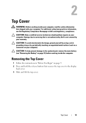
... the display back cover. 3 Slide and lift the top cover. Removing the Top Cover 1 Follow the instructions in "Before You Begin" on page 9. 2 Press and hold the release button that is not authorized by Dell is not covered by periodically touching an unpainted metal surface (such as a connector on your computer). Top Cover 13 CAUTION: Only a certified service technician should perform repairs on page...
... the display back cover. 3 Slide and lift the top cover. Removing the Top Cover 1 Follow the instructions in "Before You Begin" on page 9. 2 Press and hold the release button that is not authorized by Dell is not covered by periodically touching an unpainted metal surface (such as a connector on your computer). Top Cover 13 CAUTION: Only a certified service technician should perform repairs on page...

Service Manual
Page 15
... computer, use batteries designed for this particular Dell computer. For additional safety best practices information, see the Regulatory Compliance Homepage at dell.com/regulatory_compliance. Removing the Battery 1 Follow the instructions in "Before You Begin" on your computer. 3 Battery WARNING: Before working inside your computer, read the safety information that is not authorized by Dell is not covered by...
... computer, use batteries designed for this particular Dell computer. For additional safety best practices information, see the Regulatory Compliance Homepage at dell.com/regulatory_compliance. Removing the Battery 1 Follow the instructions in "Before You Begin" on your computer. 3 Battery WARNING: Before working inside your computer, read the safety information that is not authorized by Dell is not covered by...
Service Manual
Page 17
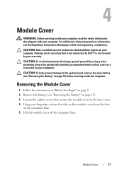
... base cover. 4 Using your warranty. CAUTION: Only a certified service technician should perform repairs on your computer). Module Cover 17 4 Module Cover WARNING: Before working inside your computer, read the safety information that is not authorized by Dell™ is not covered by periodically touching an unpainted metal surface (such as a connector on your computer. Removing the Module Cover 1 Follow the instructions in...
... base cover. 4 Using your warranty. CAUTION: Only a certified service technician should perform repairs on your computer). Module Cover 17 4 Module Cover WARNING: Before working inside your computer, read the safety information that is not authorized by Dell™ is not covered by periodically touching an unpainted metal surface (such as a connector on your computer. Removing the Module Cover 1 Follow the instructions in...

Service Manual
Page 19
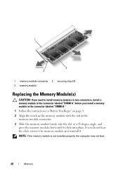
... using a wrist grounding strap or by periodically touching an unpainted metal surface (such as a connector on page 17). Removing the Memory Module(s) 1 Follow the instructions in your Setup Guide for information on the type of the memory-module connector until the memory module pops up. 5 Remove the memory module from the memory-module connector. CAUTION: Only a certified service technician should perform repairs on page 15) before working...
... using a wrist grounding strap or by periodically touching an unpainted metal surface (such as a connector on page 17). Removing the Memory Module(s) 1 Follow the instructions in your Setup Guide for information on the type of the memory-module connector until the memory module pops up. 5 Remove the memory module from the memory-module connector. CAUTION: Only a certified service technician should perform repairs on page 15) before working...
Service Manual
Page 20
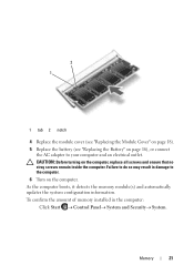
... the instructions in "Before You Begin" on page 9. 2 Align the notch in the memory module with the tab in the memory-module connector. 3 Slide the memory module firmly into place. NOTE: If the memory module is not installed properly, the computer may not boot. 20 Memory 1 3 2 1 memory-module connector 2 securing clips (2) 3 memory module Replacing the Memory Module(s) CAUTION: If you need to install memory modules in...
... the instructions in "Before You Begin" on page 9. 2 Align the notch in the memory module with the tab in the memory-module connector. 3 Slide the memory module firmly into place. NOTE: If the memory module is not installed properly, the computer may not boot. 20 Memory 1 3 2 1 memory-module connector 2 securing clips (2) 3 memory module Replacing the Memory Module(s) CAUTION: If you need to install memory modules in...
Service Manual
Page 21
...;Control PanelSystem and SecuritySystem. As the computer boots, it detects the memory module(s) and automatically updates the system configuration information. To confirm the amount of memory installed in damage to the computer. 6 Turn on page 16), or connect the AC adapter to your computer and an electrical outlet. 2 1 1 tab 2 notch 4 Replace the module cover (see "Replacing...
...;Control PanelSystem and SecuritySystem. As the computer boots, it detects the memory module(s) and automatically updates the system configuration information. To confirm the amount of memory installed in damage to the computer. 6 Turn on page 16), or connect the AC adapter to your computer and an electrical outlet. 2 1 1 tab 2 notch 4 Replace the module cover (see "Replacing...
Service Manual
Page 23
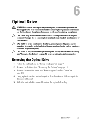
... (see "Removing the Battery" on page 15) before working inside the computer. Removing the Optical Drive 1 Follow the instructions in "Before You Begin" on page 9. 2 Remove the battery (see "Removing the Battery" on your computer, read the safety information that is not authorized by Dell is not covered by periodically touching an unpainted metal surface (such as a connector on page 17). 4 Using a plastic...
... (see "Removing the Battery" on page 15) before working inside the computer. Removing the Optical Drive 1 Follow the instructions in "Before You Begin" on page 9. 2 Remove the battery (see "Removing the Battery" on your computer, read the safety information that is not authorized by Dell is not covered by periodically touching an unpainted metal surface (such as a connector on page 17). 4 Using a plastic...
Service Manual
Page 27
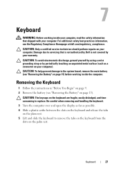
... service technician should perform repairs on your computer). Removing the Keyboard 1 Follow the instructions in "Before You Begin" on the palm rest. CAUTION: To avoid electrostatic discharge, ground yourself by using a wrist grounding strap or by your computer. CAUTION: To help prevent damage to replace. For additional safety best practices information, see "Removing the Battery" on page 15) before working...
... service technician should perform repairs on your computer). Removing the Keyboard 1 Follow the instructions in "Before You Begin" on the palm rest. CAUTION: To avoid electrostatic discharge, ground yourself by using a wrist grounding strap or by your computer. CAUTION: To help prevent damage to replace. For additional safety best practices information, see "Removing the Battery" on page 15) before working...
Service Manual
Page 37
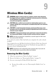
...-Card installed. Your computer has one full Mini-Card slot for Wireless Wide Area Network (WWAN) and one half Mini-Card slot for Worldwide Interoperability for Mini-Cards from sources other than Dell. If you are removing the WiMax/WWAN Mini-Card: a Remove the module cover (see "Removing the Module Cover" on page 15) before working inside the computer. Wireless Mini-Card(s) 37 Removing the Mini-Card(s) 1 Follow the instructions in...
...-Card installed. Your computer has one full Mini-Card slot for Wireless Wide Area Network (WWAN) and one half Mini-Card slot for Worldwide Interoperability for Mini-Cards from sources other than Dell. If you are removing the WiMax/WWAN Mini-Card: a Remove the module cover (see "Removing the Module Cover" on page 15) before working inside the computer. Wireless Mini-Card(s) 37 Removing the Mini-Card(s) 1 Follow the instructions in...
Service Manual
Page 39
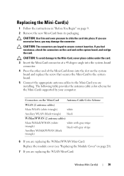
...-Card Antenna Cable Color Scheme WLAN (2 antenna cables) Main WLAN (white triangle) white Auxiliary WLAN (black triangle) black WiMax/WWAN (2 antenna cables) Main WiMaX/WWAN (white triangle) Auxillary WiMaX/WWAN (black triangle) white with gray stripe black with gray stripe 6 If you are installing. If you use excessive force, you are replacing the WiMax/WWAN Mini-Card: Replace the module cover (see "Replacing the Module Cover" on page...
...-Card Antenna Cable Color Scheme WLAN (2 antenna cables) Main WLAN (white triangle) white Auxiliary WLAN (black triangle) black WiMax/WWAN (2 antenna cables) Main WiMaX/WWAN (white triangle) Auxillary WiMaX/WWAN (black triangle) white with gray stripe black with gray stripe 6 If you are installing. If you use excessive force, you are replacing the WiMax/WWAN Mini-Card: Replace the module cover (see "Replacing the Module Cover" on page...

Service Manual
Page 40
NOTE: If you must install the appropriate drivers and utilities. 40 Wireless Mini-Card(s) CAUTION: Before turning on page 16). Failure to do so may result in damage to step 8 in "Replacing the Palm-Rest Assembly" on page 34. 8 Replace the battery (see "Replacing the Battery" on the computer, replace all screws and ensure that no stray screws remain inside the computer. Follow the instructions from a source other than Dell, you are installing a communication card from step 4 to the computer. 9 Install the drivers and utilities for your computer, as required.
NOTE: If you must install the appropriate drivers and utilities. 40 Wireless Mini-Card(s) CAUTION: Before turning on page 16). Failure to do so may result in damage to step 8 in "Replacing the Palm-Rest Assembly" on page 34. 8 Replace the battery (see "Replacing the Battery" on the computer, replace all screws and ensure that no stray screws remain inside the computer. Follow the instructions from a source other than Dell, you are installing a communication card from step 4 to the computer. 9 Install the drivers and utilities for your computer, as required.
Service Manual
Page 41
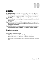
... yourself by using a wrist grounding strap or by your computer. Display Assembly Removing the Display Assembly 1 Follow the instructions in "Before You Begin" on page 9. 2 Remove the battery (see "Removing the Battery" on page 15) before working inside the computer. Display 41 10 Display WARNING: Before working inside your computer, read the safety information that is not authorized by Dell is not covered by periodically...
... yourself by using a wrist grounding strap or by your computer. Display Assembly Removing the Display Assembly 1 Follow the instructions in "Before You Begin" on page 9. 2 Remove the battery (see "Removing the Battery" on page 15) before working inside the computer. Display 41 10 Display WARNING: Before working inside your computer, read the safety information that is not authorized by Dell is not covered by periodically...
Service Manual
Page 44
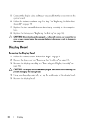
... the instructions in "Before You Begin" on page 9. 2 Remove the top cover (see "Removing the Top Cover" on page 13). 3 Remove the display assembly (see "Replacing the Battery" on page 16). CAUTION: Before turning on page 41). Be careful when removing it to prevent damaging the display bezel. 4 Using your fingertips, carefully pry up the inside the computer. CAUTION: The display bezel is extremely fragile. 5 Connect the display cable and...
... the instructions in "Before You Begin" on page 9. 2 Remove the top cover (see "Removing the Top Cover" on page 13). 3 Remove the display assembly (see "Replacing the Battery" on page 16). CAUTION: Before turning on page 41). Be careful when removing it to prevent damaging the display bezel. 4 Using your fingertips, carefully pry up the inside the computer. CAUTION: The display bezel is extremely fragile. 5 Connect the display cable and...

Service Manual
Page 47
... Display Panel 1 Follow the instructions in "Before You Begin" on page 9. 2 Replace the display-panel brackets (see "Replacing the Display-Panel Brackets" on page 50). 3 Replace the display cable (see "Removing the Display-Panel Brackets" on the display back cover. 1 2 3 1 display back cover 3 screws (8) 2 display panel 7 Make a note of the display cable and Mini-Card antenna cables routing and remove them from the routing guides on the display back cover. 8 Turn the display panel over and place it on a clean surface. 9 Remove the display cable (see "Removing the Display Cable" on page...
... Display Panel 1 Follow the instructions in "Before You Begin" on page 9. 2 Replace the display-panel brackets (see "Replacing the Display-Panel Brackets" on page 50). 3 Replace the display cable (see "Removing the Display-Panel Brackets" on the display back cover. 1 2 3 1 display back cover 3 screws (8) 2 display panel 7 Make a note of the display cable and Mini-Card antenna cables routing and remove them from the routing guides on the display back cover. 8 Turn the display panel over and place it on a clean surface. 9 Remove the display cable (see "Removing the Display Cable" on page...

Service Manual
Page 65
... installed cards from the 8-in-1 media card reader. 3 Remove the battery (see "Removing the Battery" on page 15). 4 Remove the module cover (see "Removing the Module Cover" on page 17). 5 Follow the instructions from step 4 to step 5 in "Removing the Optical Drive" on page 23. 6 Remove the memory module(s) (see "Removing the Memory Module(s)" on page 19). 7 Follow the instructions from step 3 to step 9 in "Removing the Palm-Rest Assembly" on page 31. 8 Remove the display...
... installed cards from the 8-in-1 media card reader. 3 Remove the battery (see "Removing the Battery" on page 15). 4 Remove the module cover (see "Removing the Module Cover" on page 17). 5 Follow the instructions from step 4 to step 5 in "Removing the Optical Drive" on page 23. 6 Remove the memory module(s) (see "Removing the Memory Module(s)" on page 19). 7 Follow the instructions from step 3 to step 9 in "Removing the Palm-Rest Assembly" on page 31. 8 Remove the display...
Service Manual
Page 67
... turning on page 16). 16 Replace any cards or blanks removed from the 8-in-1 media card reader. Replacing the System Board 1 Follow the instructions in "Before You Begin" on page 9. 2 Replace the processor module (see "Replacing the Processor Module" on page 80). 3 Replace the thermal cooling assembly (see "Replacing the Thermal-Cooling Assembly" on page 76). 4 Follow the instructions from step 5 to step 7 in "Replacing the Hard Drive" on page 73. 5 Turn the...
... turning on page 16). 16 Replace any cards or blanks removed from the 8-in-1 media card reader. Replacing the System Board 1 Follow the instructions in "Before You Begin" on page 9. 2 Replace the processor module (see "Replacing the Processor Module" on page 80). 3 Replace the thermal cooling assembly (see "Replacing the Thermal-Cooling Assembly" on page 76). 4 Follow the instructions from step 5 to step 7 in "Replacing the Hard Drive" on page 73. 5 Turn the...

Service Manual
Page 71
... compatibility or provide support for hard drives from a source other than Dell, you need to the system board. CAUTION: Hard drives are installing a hard drive from sources other than Dell. CAUTION: To avoid electrostatic discharge, ground yourself by using a wrist grounding strap or by your computer). NOTE: If you remove the hard drive from step 2 to step 13 in Sleep state. CAUTION: Only a certified service technician should perform repairs...
... compatibility or provide support for hard drives from a source other than Dell, you need to the system board. CAUTION: Hard drives are installing a hard drive from sources other than Dell. CAUTION: To avoid electrostatic discharge, ground yourself by using a wrist grounding strap or by your computer). NOTE: If you remove the hard drive from step 2 to step 13 in Sleep state. CAUTION: Only a certified service technician should perform repairs...


