
Setup Guide
Page 36
... or RTC battery low. Replace the battery. See the Service Manual on page 50 for assistance. Keyboard failure - Keyboard failure or loose cable. CPU fan failure - Hard-disk drive read failure - Possible hard disk drive failure during HDD POST see "Contacting Dell" on page 50 for .... Previous attempts at booting this checkpoint and contact Dell Technical Support - Replace the CPU fan. Using Support Tools NOTE: If the message you could see the Service Manual on the Dell Support website at support.dell.com or see "Contacting Dell" on page 50 for either the operating system...
... or RTC battery low. Replace the battery. See the Service Manual on page 50 for assistance. Keyboard failure - Keyboard failure or loose cable. CPU fan failure - Hard-disk drive read failure - Possible hard disk drive failure during HDD POST see "Contacting Dell" on page 50 for .... Previous attempts at booting this checkpoint and contact Dell Technical Support - Replace the CPU fan. Using Support Tools NOTE: If the message you could see the Service Manual on the Dell Support website at support.dell.com or see "Contacting Dell" on page 50 for either the operating system...
Service Manual
Page 46
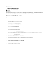
... module(s) (see Removing the Keyboard). 8. The replacement kit for the system board includes media that provides a utility for transferring the Service Tag to Contents Page System Board Assembly Dell™ Inspiron™ 1525/1526 Service Manual S-Video Board Charger Board The ...system board's BIOS chip contains the Service Tag, which is also visible on a barcode label on the bottom of the computer. Remove the keyboard (see Removing Memory Module). 3. Disconnect the processor heat sink fan...
... module(s) (see Removing the Keyboard). 8. The replacement kit for the system board includes media that provides a utility for transferring the Service Tag to Contents Page System Board Assembly Dell™ Inspiron™ 1525/1526 Service Manual S-Video Board Charger Board The ...system board's BIOS chip contains the Service Tag, which is also visible on a barcode label on the bottom of the computer. Remove the keyboard (see Removing Memory Module). 3. Disconnect the processor heat sink fan...
Service Manual
Page 47
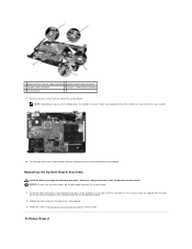
... the following procedure, follow the safety instructions in reverse order. Replace the four screws on your system configuration, the number of screws shown may be greater than the number of screws present in your system. 18. S-Video Board 1 processor heat sink fan cable connector 2 button board cable connector 3 speaker cable connector 4 wireless...
... the following procedure, follow the safety instructions in reverse order. Replace the four screws on your system configuration, the number of screws shown may be greater than the number of screws present in your system. 18. S-Video Board 1 processor heat sink fan cable connector 2 button board cable connector 3 speaker cable connector 4 wireless...


