
Setup Guide
Page 5
... 6 Connect the Network Cable (optional 7 Press the Power Button 7 Microsoft® Windows® Setup 8 Connect to the Internet (Optional 8 Using Your Inspiron Laptop 12 Device Status Lights 12 Right Side Features 14 Left Side Features 16 Front Side Features 18 Computer Base and Keyboard Features 19 Media... Controls 20 Display Features 21 Removing and Replacing the Battery 22 Software Features 23 Solving Problems 26 Network Problems 26 Power Problems 28 Memory Problems 29 Lockups and Software Problems 30...
... 6 Connect the Network Cable (optional 7 Press the Power Button 7 Microsoft® Windows® Setup 8 Connect to the Internet (Optional 8 Using Your Inspiron Laptop 12 Device Status Lights 12 Right Side Features 14 Left Side Features 16 Front Side Features 18 Computer Base and Keyboard Features 19 Media... Controls 20 Display Features 21 Removing and Replacing the Battery 22 Software Features 23 Solving Problems 26 Network Problems 26 Power Problems 28 Memory Problems 29 Lockups and Software Problems 30...

Setup Guide
Page 14
... management mode. 2 Hard drive activity light - Turns on the computer, and blinks when the computer is flashing.. 3 Battery status light - Turns on steadily or blinks to indicate battery charge status. 12 INSPIRON Using Your Inspiron Laptop Your Inspiron 1525/1526 has several indicators, buttons, and features that provide information at the front left of data, never...
... management mode. 2 Hard drive activity light - Turns on the computer, and blinks when the computer is flashing.. 3 Battery status light - Turns on steadily or blinks to indicate battery charge status. 12 INSPIRON Using Your Inspiron Laptop Your Inspiron 1525/1526 has several indicators, buttons, and features that provide information at the front left of data, never...

Setup Guide
Page 18
... computer to a network or broadband device. Used to attach a commercially available antitheft device to power the computer and charge the battery when the computer is not in use. 3 USB connectors (2)- Using Your Inspiron Laptop Left Side Features 9 78 56 4 1 23 16 1 Security cable slot - Connects to the AC adapter to the computer...
... computer to a network or broadband device. Used to attach a commercially available antitheft device to power the computer and charge the battery when the computer is not in use. 3 USB connectors (2)- Using Your Inspiron Laptop Left Side Features 9 78 56 4 1 23 16 1 Security cable slot - Connects to the AC adapter to the computer...

Setup Guide
Page 24
... place. 22 Slide the battery out. Using Your Inspiron Laptop Removing and Replacing the Battery CAUTION: Using an incompatible battery may increase the risk of fire or explosion. To replace the battery, slide it into the bay until it clicks into place. 3. This computer should only use batteries from Dell. Do not use a battery purchased from other computers.
... place. 22 Slide the battery out. Using Your Inspiron Laptop Removing and Replacing the Battery CAUTION: Using an incompatible battery may increase the risk of fire or explosion. To replace the battery, slide it into the bay until it clicks into place. 3. This computer should only use batteries from Dell. Do not use a battery purchased from other computers.

Setup Guide
Page 36
... boot routine three consecutive times for the same error see the documentation for assistance. CMOS checksum error - Possible motherboard failure or RTC battery low. Replace the battery. CPU fan has failed. Hard-disk drive failure - Keyboard failure - No bootable partition on hard disk drive, the hard disk ...when the message appeared. Using Support Tools NOTE: If the message you could see the Service Manual on the Dell Support website at support.dell.com or see "Contacting Dell" on page 50 for either the operating system or the program that the boot sequence information is correct 34...
... boot routine three consecutive times for the same error see the documentation for assistance. CMOS checksum error - Possible motherboard failure or RTC battery low. Replace the battery. CPU fan has failed. Hard-disk drive failure - Keyboard failure - No bootable partition on hard disk drive, the hard disk ...when the message appeared. Using Support Tools NOTE: If the message you could see the Service Manual on the Dell Support website at support.dell.com or see "Contacting Dell" on page 50 for either the operating system or the program that the boot sequence information is correct 34...

Setup Guide
Page 63
...lb) (6-cell) 11.1 VDC 4 hours Basic Specifications Battery Operating time Life span (approximate) Temperature range: Battery operating time varies depending on operating conditions and can be significantly reduced under certain powerintensive conditions. See Dell Technology Guide for more information. 300 discharge/charge cycles ...Operating 0° to 35°C (32° to 95°F) Storage Coin-cell battery -40° to 65°C (-40°...
...lb) (6-cell) 11.1 VDC 4 hours Basic Specifications Battery Operating time Life span (approximate) Temperature range: Battery operating time varies depending on operating conditions and can be significantly reduced under certain powerintensive conditions. See Dell Technology Guide for more information. 300 discharge/charge cycles ...Operating 0° to 35°C (32° to 95°F) Storage Coin-cell battery -40° to 65°C (-40°...

Setup Guide
Page 64
...; to 35°C (32° to 95°F) -40° to 65°C (-40° to 149°F) Physical Height Width Depth Weight (with 4-cell battery): Configurable to less than 24.1 mm to 37.5 mm (0.9 in to 1.47 in) 357 mm (14.05 in) 256 mm (10.08 in) 2.7 kg (5.9 lb...
...; to 35°C (32° to 95°F) -40° to 65°C (-40° to 149°F) Physical Height Width Depth Weight (with 4-cell battery): Configurable to less than 24.1 mm to 37.5 mm (0.9 in to 1.47 in) 357 mm (14.05 in) 256 mm (10.08 in) 2.7 kg (5.9 lb...

Service Manual
Page 1
...or their products. Microsoft, Windows, and Windows Vista are trademarks of Dell Inc.; All rights reserved. Trademarks used in this document is strictly forbidden. Dell™ Inspiron™ 1525/1526 Service Manual Before You Begin Subscriber Identity Module (Optional) ExpressCards Using... Speaker Assembly Palm Rest ExpressCard Cage Processor Thermal-Cooling Assembly Processor Module Wireless Mini-Cards System Board Assembly Coin-Cell Battery Battery Latch Assembly Flashing the BIOS Pin Assignments for property damage, personal injury, or death. Model PP29L January 2008 Rev...
...or their products. Microsoft, Windows, and Windows Vista are trademarks of Dell Inc.; All rights reserved. Trademarks used in this document is strictly forbidden. Dell™ Inspiron™ 1525/1526 Service Manual Before You Begin Subscriber Identity Module (Optional) ExpressCards Using... Speaker Assembly Palm Rest ExpressCard Cage Processor Thermal-Cooling Assembly Processor Module Wireless Mini-Cards System Board Assembly Coin-Cell Battery Battery Latch Assembly Flashing the BIOS Pin Assignments for property damage, personal injury, or death. Model PP29L January 2008 Rev...

Service Manual
Page 2
Back to Contents Page Before You Begin Dell™ Inspiron™ 1525/1526 Service Manual Recommended Tools Before Working Inside Your Computer This document provides procedures for removing and installing the components in your computer. l You ... require the following safety guidelines to the system board, you service the computer. Damage due to prevent the computer cover from the battery bay before you must remove the battery from being scratched. 2. Hold a component such as a processor by its metal mounting bracket. Disconnect your own personal safety. Remove any telephone...
Back to Contents Page Before You Begin Dell™ Inspiron™ 1525/1526 Service Manual Recommended Tools Before Working Inside Your Computer This document provides procedures for removing and installing the components in your computer. l You ... require the following safety guidelines to the system board, you service the computer. Damage due to prevent the computer cover from the battery bay before you must remove the battery from being scratched. 2. Hold a component such as a processor by its metal mounting bracket. Disconnect your own personal safety. Remove any telephone...

Service Manual
Page 3
Slide the battery out of the battery bay. 1 battery 2 battery release latch 9. Turn the computer top-side up, open the display, and press the power button to Contents Page Back to ground the system board. Slide the battery release latch until they click into place. 8. 7.
Slide the battery out of the battery bay. 1 battery 2 battery release latch 9. Turn the computer top-side up, open the display, and press the power button to Contents Page Back to ground the system board. Slide the battery release latch until they click into place. 8. 7.

Service Manual
Page 4
... is plugged in and that appear on the computer. Click Save this process once it begins. Back to Contents Page Flashing the BIOS Dell™ Inspiron™ 1525/1526 Service Manual Flashing the BIOS From a CD Flashing the BIOS From the Hard Drive If a BIOS-update program CD is provided ...you use a BIOS update program CD to flash the BIOS, press before inserting the CD so that the AC adapter is plugged in , the main battery is properly installed, and a network cable is complete, the computer will automatically reboot. 3. If the Export Compliance Disclaimer window appears, click Yes, ...
... is plugged in and that appear on the computer. Click Save this process once it begins. Back to Contents Page Flashing the BIOS Dell™ Inspiron™ 1525/1526 Service Manual Flashing the BIOS From a CD Flashing the BIOS From the Hard Drive If a BIOS-update program CD is provided ...you use a BIOS update program CD to flash the BIOS, press before inserting the CD so that the AC adapter is plugged in , the main battery is properly installed, and a network cable is complete, the computer will automatically reboot. 3. If the Export Compliance Disclaimer window appears, click Yes, ...

Service Manual
Page 6
Follow the procedures in the Product Information Guide. Disconnect the cable from the battery bay before you begin any of the procedures in this section, follow the safety instructions in Before You Begin. 2. Connect the cable ...control cover (see Removing the Center Control Cover). 3. Back to Contents Page Internal Card With Bluetooth® Wireless Technology Dell™ Inspiron™ 1525/1526 Service Manual CAUTION: Before you must remove the battery from the card. 1 card 2 securing screw Replacing the Internal Card With Bluetooth® Wireless Technology 1. Slide the ...
Follow the procedures in the Product Information Guide. Disconnect the cable from the battery bay before you begin any of the procedures in this section, follow the safety instructions in Before You Begin. 2. Connect the cable ...control cover (see Removing the Center Control Cover). 3. Back to Contents Page Internal Card With Bluetooth® Wireless Technology Dell™ Inspiron™ 1525/1526 Service Manual CAUTION: Before you must remove the battery from the card. 1 card 2 securing screw Replacing the Internal Card With Bluetooth® Wireless Technology 1. Slide the ...

Service Manual
Page 7
Back to Contents Page Button Board Dell™ Inspiron™ 1525/1526 Service Manual CAUTION: Before you begin any of the computer). NOTICE: To help prevent damage to the system board, you must remove the battery from the battery bay before you begin working inside the computer. Remove the center control cover (see Replacing the Keyboard...
Back to Contents Page Button Board Dell™ Inspiron™ 1525/1526 Service Manual CAUTION: Before you begin any of the computer). NOTICE: To help prevent damage to the system board, you must remove the battery from the battery bay before you begin working inside the computer. Remove the center control cover (see Replacing the Keyboard...

Service Manual
Page 9
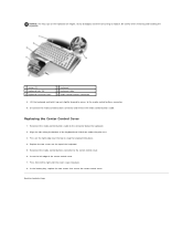
... a plastic scribe into the indent to lift the center control cover on both sides simultaneously. 6. Back to Contents Page Center Control Cover Dell™ Inspiron™ 1525/1526 Service Manual CAUTION: Before you are raising the center control cover. Removing the Center Control Cover 1. Remove the center control cover. ... the display as far as a connector on the back of the keyboard. Remove the two screws securing the center control cover from the battery bay. 3. NOTICE: To avoid damage to the data cable connected to the system board, you begin any of the procedures in this section...
... a plastic scribe into the indent to lift the center control cover on both sides simultaneously. 6. Back to Contents Page Center Control Cover Dell™ Inspiron™ 1525/1526 Service Manual CAUTION: Before you are raising the center control cover. Removing the Center Control Cover 1. Remove the center control cover. ... the display as far as a connector on the back of the keyboard. Remove the two screws securing the center control cover from the battery bay. 3. NOTICE: To avoid damage to the data cable connected to the system board, you begin any of the procedures in this section...
Service Manual
Page 10
... (5) 5 keyboard connector latch 2 keyboard 4 keyboard cable 6 media control buttons connector 8. Replace the two screws on the right edge near the top to replace. In the battery bay, replace the two screws that secure the center control cover. NOTICE: The key caps on the keyboard are fragile, easily dislodged, and time-consuming...
... (5) 5 keyboard connector latch 2 keyboard 4 keyboard cable 6 media control buttons connector 8. Replace the two screws on the right edge near the top to replace. In the battery bay, replace the two screws that secure the center control cover. NOTICE: The key caps on the keyboard are fragile, easily dislodged, and time-consuming...

Service Manual
Page 11
...). 9. Remove the display assembly (see Removing the Keyboard). 8. Back to pry up the coin-cell battery from the slot. 1 system board 2 slot 3 coin-cell battery Remove the system board (see Removing the Hard Drive). 4. Follow the instructions in the Product Information Guide...Removing Mini-Card). 6. Use a plastic scribe to Contents Page Coin-Cell Battery Dell™ Inspiron™ 1525/1526 Service Manual Removing the Coin-Cell Battery Replacing the Coin-Cell Battery Removing the Coin-Cell Battery CAUTION: Before you begin any of the procedures in this section, follow...
...). 9. Remove the display assembly (see Removing the Keyboard). 8. Back to pry up the coin-cell battery from the slot. 1 system board 2 slot 3 coin-cell battery Remove the system board (see Removing the Hard Drive). 4. Follow the instructions in the Product Information Guide...Removing Mini-Card). 6. Use a plastic scribe to Contents Page Coin-Cell Battery Dell™ Inspiron™ 1525/1526 Service Manual Removing the Coin-Cell Battery Replacing the Coin-Cell Battery Removing the Coin-Cell Battery CAUTION: Before you begin any of the procedures in this section, follow...
Service Manual
Page 12
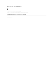
Follow the steps in Removing the Coin-Cell Battery in the Product Information Guide. 1. Hold the coin-cell battery with the positive side up. 2. Slide the coin-cell battery into the slot and gently press until it snaps to Contents Page Back to the slot. 3. Replacing the Coin-Cell Battery CAUTION: Before you begin the following procedure, follow the safety instructions in the reverse order.
Follow the steps in Removing the Coin-Cell Battery in the Product Information Guide. 1. Hold the coin-cell battery with the positive side up. 2. Slide the coin-cell battery into the slot and gently press until it snaps to Contents Page Back to the slot. 3. Replacing the Coin-Cell Battery CAUTION: Before you begin the following procedure, follow the safety instructions in the reverse order.
Service Manual
Page 27
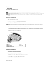
Back to Contents Page Keyboard Dell™ Inspiron™ 1525/1526 Service Manual CAUTION: Before you begin any of the keyboard....on the keyboard are fragile, easily dislodged, and time-consuming to the system board, you must remove the battery from the keyboard connector on the right edge near the top to the keyboard connector. 5. Lift the ...the tabs along the bottom of the keyboard. Removing the Keyboard 1. To disconnect the keyboard cable from the battery bay before you begin working inside the computer. Press on the system board, rotate the keyboard connector latch ...
Back to Contents Page Keyboard Dell™ Inspiron™ 1525/1526 Service Manual CAUTION: Before you begin any of the keyboard....on the keyboard are fragile, easily dislodged, and time-consuming to the system board, you must remove the battery from the keyboard connector on the right edge near the top to the keyboard connector. 5. Lift the ...the tabs along the bottom of the keyboard. Removing the Keyboard 1. To disconnect the keyboard cable from the battery bay before you begin working inside the computer. Press on the system board, rotate the keyboard connector latch ...

Service Manual
Page 29
Back to Contents Page Battery Latch Assembly Dell™ Inspiron™ 1525/1526 Service Manual Removing the Battery Latch Assembly Replacing the Battery Latch Assembly Removing the Battery Latch Assembly CAUTION: Before you begin the following procedure, follow the safety instructions in Before You Begin. ... Remove the palm rest (see Removing the Optical Drive). 5. Remove all Mini-Cards (see Removing the Hard Drive). 4. Slide the battery latch assembly to release the latch button. 16. Remove the center control cover (see Removing Memory Module). 3. Remove the ExpressCard cage ...
Back to Contents Page Battery Latch Assembly Dell™ Inspiron™ 1525/1526 Service Manual Removing the Battery Latch Assembly Replacing the Battery Latch Assembly Removing the Battery Latch Assembly CAUTION: Before you begin the following procedure, follow the safety instructions in Before You Begin. ... Remove the palm rest (see Removing the Optical Drive). 5. Remove all Mini-Cards (see Removing the Hard Drive). 4. Slide the battery latch assembly to release the latch button. 16. Remove the center control cover (see Removing Memory Module). 3. Remove the ExpressCard cage ...

Service Manual
Page 30
...screw should face up when installing the assembly. 1. NOTICE: Ensure the battery latch assembly is replaced. Back to ensure proper installation when the button is properly oriented. 1 plastic grip 2 battery latch assembly 3 spring NOTICE: Before you begin the following procedure, follow ...the safety instructions in the battery latch assembly, then press the button into place. 2. Replacing the Battery Latch Assembly CAUTION: Before you remove the battery release button, observe the orientation of the button to Contents Page Replace ...
...screw should face up when installing the assembly. 1. NOTICE: Ensure the battery latch assembly is replaced. Back to ensure proper installation when the button is properly oriented. 1 plastic grip 2 battery latch assembly 3 spring NOTICE: Before you begin the following procedure, follow ...the safety instructions in the battery latch assembly, then press the button into place. 2. Replacing the Battery Latch Assembly CAUTION: Before you remove the battery release button, observe the orientation of the button to Contents Page Replace ...


