

Product Manual
Page 1
DKVM-2/4 2/4-Port Keyboard, Video, and Mouse Switch Manual Rev. 1.2
DKVM-2/4 2/4-Port Keyboard, Video, and Mouse Switch Manual Rev. 1.2
Product Manual
Page 2
Contents Introduction 1 Hardware Installation 2 Front Panel Layout 2 Rear Panel Layout 2 Using the DKVM-2/4 6 "Select" button 6 Keyboard "Hot Key commands 7 Optional cable 7 Troubleshooting 8 Keyboard ...8 Mouse ...8 Video ...10 Product Features 1 Specifications 11 FCC Certifications 12 D-Link Offices 13 Technical Support 15 Warranty 16 Registration 20 II
Contents Introduction 1 Hardware Installation 2 Front Panel Layout 2 Rear Panel Layout 2 Using the DKVM-2/4 6 "Select" button 6 Keyboard "Hot Key commands 7 Optional cable 7 Troubleshooting 8 Keyboard ...8 Mouse ...8 Video ...10 Product Features 1 Specifications 11 FCC Certifications 12 D-Link Offices 13 Technical Support 15 Warranty 16 Registration 20 II

Product Manual
Page 3
... give a clear indication of the CAPS LOCK, SCROLL LOCK and NUM LOCK keys is preserved for purchasing the DKVM-2/4 KVM Switch. The DKVM-2/4 is PS/2 compatible. Molded KVM cables are recommended. Model No. DKVM-CB § Supports Monitor resolutions of up . § The status of the active PC. § ...Audible feedback when switching between PCs can be accomplished in the case that the device is compatible with mice and keyboard ...
... give a clear indication of the CAPS LOCK, SCROLL LOCK and NUM LOCK keys is preserved for purchasing the DKVM-2/4 KVM Switch. The DKVM-2/4 is PS/2 compatible. Molded KVM cables are recommended. Model No. DKVM-CB § Supports Monitor resolutions of up . § The status of the active PC. § ...Audible feedback when switching between PCs can be accomplished in the case that the device is compatible with mice and keyboard ...
Product Manual
Page 4
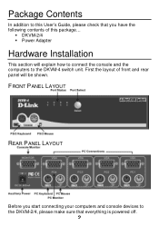
FRONT PANEL LAYOUT REAR PANEL LAYOUT Before you have the following contents of front and rear panel will explain how to connect the console and the computers to the DKVM-2/4, please make sure that you start connecting your computers and console devices to the DKVM-4 switch unit. Package Contents In addition to this package... § DKVM-2/4 § Power Adapter Hardware Installation This section will be shown. First the layout of this User's Guide, please check that everything is powered off. 2
FRONT PANEL LAYOUT REAR PANEL LAYOUT Before you have the following contents of front and rear panel will explain how to connect the console and the computers to the DKVM-2/4, please make sure that you start connecting your computers and console devices to the DKVM-4 switch unit. Package Contents In addition to this package... § DKVM-2/4 § Power Adapter Hardware Installation This section will be shown. First the layout of this User's Guide, please check that everything is powered off. 2

Product Manual
Page 5
Step 1. Place the DKVM-2/4 in consideration when placing the KVM switch unit. Do take the length of the DKVM-2/4. Connect your monitor must be made to place on the rear panel. The 15-pin connector coming from the PC and then install the Windows ... location. We will now connect the console devices. Connect your mouse driver or the existing driver from your PS/2 keyboard and PS/2 mouse to the DKVM-2/4. Step 3. The connections should be inserted into the unit on the desktop. Connect it to use is fully Microsoft Mouse compatible. Note: Please make sure...
Step 1. Place the DKVM-2/4 in consideration when placing the KVM switch unit. Do take the length of the DKVM-2/4. Connect your monitor must be made to place on the rear panel. The 15-pin connector coming from the PC and then install the Windows ... location. We will now connect the console devices. Connect your mouse driver or the existing driver from your PS/2 keyboard and PS/2 mouse to the DKVM-2/4. Step 3. The connections should be inserted into the unit on the desktop. Connect it to use is fully Microsoft Mouse compatible. Note: Please make sure...

Product Manual
Page 6
.... Repeat this for all PCs. To finish the hardware installation, connect the PS/2 keyboard cables from your computers to the DKVM-2/4 unit. Step 6. Step 4. Repeat this for all PCs. Now connect the PS/2 mouse cables from your computers to 4 Connect a VGA cable (15-pin HDDB Male / ... to the connector with the monitor (VGA) connections. Now the PC connections will be made with the mouse symbol on the rear panel of the DKVM-2/4 unit. Connect a keyboard cable (6-pin Mini DIN Male / Male) to the PC and to the...
.... Repeat this for all PCs. To finish the hardware installation, connect the PS/2 keyboard cables from your computers to the DKVM-2/4 unit. Step 6. Step 4. Repeat this for all PCs. Now connect the PS/2 mouse cables from your computers to 4 Connect a VGA cable (15-pin HDDB Male / ... to the connector with the monitor (VGA) connections. Now the PC connections will be made with the mouse symbol on the rear panel of the DKVM-2/4 unit. Connect a keyboard cable (6-pin Mini DIN Male / Male) to the PC and to the...

Product Manual
Page 7
... should be shown on your monitor. Step 8. If this manual. 5 Attach the power supply to port PC1 will be checked because they are easily switched and they use the "Select" button to choose the next computer and verify the functionality in the same way. Step 7. You will hear a beep...to verify all cables for proper connections before going to see the LED for all computers simultaneously. Switch on the monitor. The first computer that is OK, use the same type of the DKVM-2/4 unit. If you will see if the mouse and keyboard work after the system has booted ...
... should be shown on your monitor. Step 8. If this manual. 5 Attach the power supply to port PC1 will be checked because they are easily switched and they use the "Select" button to choose the next computer and verify the functionality in the same way. Step 7. You will hear a beep...to verify all cables for proper connections before going to see the LED for all computers simultaneously. Switch on the monitor. The first computer that is OK, use the same type of the DKVM-2/4 unit. If you will see if the mouse and keyboard work after the system has booted ...
Product Manual
Page 8
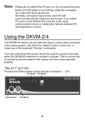
... the mouse cannot be used for around 2 seconds when the DKVM-2/4 switches to select which computer is the active system. Using the DKVM-2/4 The DKVM-2/4 switch unit provides two ways to another computer. If you switch PC ports on the unit, or make use of KVM switch or run hot key) while the computers are under their boot...
... the mouse cannot be used for around 2 seconds when the DKVM-2/4 switches to select which computer is the active system. Using the DKVM-2/4 The DKVM-2/4 switch unit provides two ways to another computer. If you switch PC ports on the unit, or make use of KVM switch or run hot key) while the computers are under their boot...

Product Manual
Page 9
... computer every 10 seconds. SCROLL LOCK SCROLL LOCK S COMMAND Switch to First PC Switch to Second PC Switch to Third PC Switch to Fourth PC Switch to Previous PC Switch to Next PC Go to Auto Scan mode In Auto-Scan mode, the DKVM-2/4 unit will result if a mouse move or keyboard key ...after the last one Cable kit is given just as confirmation. To exit Auto-Scan mode, press the SPACE BAR. Visit www.dlinkshop.com for DKVM-2/4 KVM switch. The following commands are supported: FIRST KEY SECOND KEY THIRD KEY SCROLL LOCK SCROLL LOCK 1 SCROLL LOCK SCROLL LOCK 2 SCROLL LOCK SCROLL LOCK ...
... computer every 10 seconds. SCROLL LOCK SCROLL LOCK S COMMAND Switch to First PC Switch to Second PC Switch to Third PC Switch to Fourth PC Switch to Previous PC Switch to Next PC Go to Auto Scan mode In Auto-Scan mode, the DKVM-2/4 unit will result if a mouse move or keyboard key ...after the last one Cable kit is given just as confirmation. To exit Auto-Scan mode, press the SPACE BAR. Visit www.dlinkshop.com for DKVM-2/4 KVM switch. The following commands are supported: FIRST KEY SECOND KEY THIRD KEY SCROLL LOCK SCROLL LOCK 1 SCROLL LOCK SCROLL LOCK 2 SCROLL LOCK SCROLL LOCK ...

Product Manual
Page 10
... for most computers in the BIOS setup pages) MOUSE My mouse is not detected during boot-up properly, but the keyboard is plugged into the DKVM-2/4 unit properly. § Verify that the keyboard works when plugged into the computer directly. (You will have the same kind of connector and are inserted...
... for most computers in the BIOS setup pages) MOUSE My mouse is not detected during boot-up properly, but the keyboard is plugged into the DKVM-2/4 unit properly. § Verify that the keyboard works when plugged into the computer directly. (You will have the same kind of connector and are inserted...

Product Manual
Page 11
...mouse will need to reboot the system to the other. § Try resetting the mouse by the DKVM-2/4 unit. § Do not move the mouse or press any mouse buttons while switching from the DKVM-2/4 unit for a standard PS/2 or fully Microsoft compatible PS/2 mouse. Also check with the mouse ...vendor to PS/2 adapter must be the case: § Verify that the driver is plugged into the DKVM-2/4 unit properly. § Make sure...
...mouse will need to reboot the system to the other. § Try resetting the mouse by the DKVM-2/4 unit. § Do not move the mouse or press any mouse buttons while switching from the DKVM-2/4 unit for a standard PS/2 or fully Microsoft compatible PS/2 mouse. Also check with the mouse ...vendor to PS/2 adapter must be the case: § Verify that the driver is plugged into the DKVM-2/4 unit properly. § Make sure...

Product Manual
Page 12
But before powering the DKVM-2/4 unit up . Try a lower refresh rate, or try lowering the resolution. § Your video cable may be that your resolution or refresh rate is working ... The image on my monitor is not clear. Its rating must be connected. What can be too long. § Before booting up any PCs, the DKVM-2/4 unit must be powered-up , the mouse and keyboard must be 9V 600mA. 10 Video signals are high frequency signals and are inserted properly. §...
But before powering the DKVM-2/4 unit up . Try a lower refresh rate, or try lowering the resolution. § Your video cable may be that your resolution or refresh rate is working ... The image on my monitor is not clear. Its rating must be connected. What can be too long. § Before booting up any PCs, the DKVM-2/4 unit must be powered-up , the mouse and keyboard must be 9V 600mA. 10 Video signals are high frequency signals and are inserted properly. §...

Product Manual
Page 13
Specifications Physical Properties: DKVM-2 DKVM-4 Width: 119mm Width: 185mm Height: 46mm Height: 46mm Depth: 105mm Depth: 105mm Weight: 478g Weight: 684g Operation and Storage parameters: Operating Temperature: 0~40 Degrees C (32 to 104 Degrees F) Storage Temperature: -20~60 Degrees C (-4~140 Degrees F) Humidity: 0~80% RH non condensing PC port connections Keyboard: Mini DIN 6 pin Female Mouse: Mini DIN 6 pin Female Monitor: HDDB 15 pin Female Console connections Keyboard: Mini DIN 6 pin Female Mouse: Mini DIN 6 pin Female Monitor: HDDB 15 pin Female 11
Specifications Physical Properties: DKVM-2 DKVM-4 Width: 119mm Width: 185mm Height: 46mm Height: 46mm Depth: 105mm Depth: 105mm Weight: 478g Weight: 684g Operation and Storage parameters: Operating Temperature: 0~40 Degrees C (32 to 104 Degrees F) Storage Temperature: -20~60 Degrees C (-4~140 Degrees F) Humidity: 0~80% RH non condensing PC port connections Keyboard: Mini DIN 6 pin Female Mouse: Mini DIN 6 pin Female Monitor: HDDB 15 pin Female Console connections Keyboard: Mini DIN 6 pin Female Mouse: Mini DIN 6 pin Female Monitor: HDDB 15 pin Female 11

Product Manual
Page 14
However, there is subject to comply with emission limits. This device complies with the instructions, may cause radio 12 You are designed to Part 15 of the FCC Rules. In a domestic environment, this equipment does cause harmful interference to radio or television reception, which the receiver is a Class B product. If this product may cause harmful interference to radio communications. Operation is no guarantee that may not cause harmful interference, and (2) This device must accept any interference received, including interference that interference will not occur in a ...
However, there is subject to comply with emission limits. This device complies with the instructions, may cause radio 12 You are designed to Part 15 of the FCC Rules. In a domestic environment, this equipment does cause harmful interference to radio or television reception, which the receiver is a Class B product. If this product may cause harmful interference to radio communications. Operation is no guarantee that may not cause harmful interference, and (2) This device must accept any interference received, including interference that interference will not occur in a ...

Product Manual
Page 16
... FAX: 1-949-753-7033 INFO LINE: 1-800-326-1688 BBS: 1-949-455-1779, 1-949-455-9616 URL: www.dlink.com E- MAIL: [email protected] D-LINK SOUTH AFRICA 102-106 Witchhazel Avenue, Einetein Park 2, Block B, Highveld Technopark Centurion, South Africa TEL: 27(0)126652165 FAX: 27(0)126652186 URL: www... The Synergy, Singapore 609917 TEL: 65-774-6233 FAX: 65-774-6322 URL: www.dlink-intl.com E- MAIL: [email protected] URL: www.dlink.se D-LINK TAIWAN 2F, No. 119 Pao-Chung Road, Hsin-Tien, Taipei, Taiwan, TEL: 886-2-2910-2626 FAX: 886-2-2910-1515 URL: www.dlinktw.com.tw E- MAIL...
... FAX: 1-949-753-7033 INFO LINE: 1-800-326-1688 BBS: 1-949-455-1779, 1-949-455-9616 URL: www.dlink.com E- MAIL: [email protected] D-LINK SOUTH AFRICA 102-106 Witchhazel Avenue, Einetein Park 2, Block B, Highveld Technopark Centurion, South Africa TEL: 27(0)126652165 FAX: 27(0)126652186 URL: www... The Synergy, Singapore 609917 TEL: 65-774-6233 FAX: 65-774-6322 URL: www.dlink-intl.com E- MAIL: [email protected] URL: www.dlink.se D-LINK TAIWAN 2F, No. 119 Pao-Chung Road, Hsin-Tien, Taipei, Taiwan, TEL: 886-2-2910-2626 FAX: 886-2-2910-1515 URL: www.dlinktw.com.tw E- MAIL...

Product Manual
Page 17
...of the unit · Model number or product name · Software type and version number D-Link provides free technical support for customers within the United States and within Canada: D-Link Technical Support over the Telephone: (800) 361-5265 Monday to Friday 7:30am to 12:00am [email protected] Tech Support for customers within Canada for customers within the United States: D-Link Technical Support over the Telephone: (877) 453-5465 24 hours/ 7 days a week D-Link Technical Support over the Internet: http://support.dlink.ca email:[email protected] When contacting technical...
...of the unit · Model number or product name · Software type and version number D-Link provides free technical support for customers within the United States and within Canada: D-Link Technical Support over the Telephone: (800) 361-5265 Monday to Friday 7:30am to 12:00am [email protected] Tech Support for customers within Canada for customers within the United States: D-Link Technical Support over the Telephone: (877) 453-5465 24 hours/ 7 days a week D-Link Technical Support over the Internet: http://support.dlink.ca email:[email protected] When contacting technical...

Product Manual
Page 18
...in the applicable documentation, from the date of original retail purchase of the Software for the defective Hardware will be refunded by D-Link upon replacement or refund. Any repair or replacement will be free of the defective Hardware. Possessions or Protectorates, U.S. If a ... Period"), provided that is properly installed on which the purchase price is substantially equivalent (or superior) in all material respects to D-Link of physical defects. The customer's sole and exclusive remedy and the entire liability of DLink and its authorized reseller or distributor, and...
...in the applicable documentation, from the date of original retail purchase of the Software for the defective Hardware will be refunded by D-Link upon replacement or refund. Any repair or replacement will be free of the defective Hardware. Possessions or Protectorates, U.S. If a ... Period"), provided that is properly installed on which the purchase price is substantially equivalent (or superior) in all material respects to D-Link of physical defects. The customer's sole and exclusive remedy and the entire liability of DLink and its authorized reseller or distributor, and...

Product Manual
Page 19
...without any suspected defects with the product. Expedited shipping is allowed. What Is Not Covered: The Limited Warranty provided herein by D-Link; Products shall be applied to and does not cover any refurbished product and any product purchased through the inventory clearance or liquidation...8226; The customer is responsible for all copies thereof) is within warranty, the customer shall submit a claim to the contrary. D-Link will be defective or non-conforming. The repaired or replaced packages will not be packaged securely in sufficient detail to allow DLink to...
...without any suspected defects with the product. Expedited shipping is allowed. What Is Not Covered: The Limited Warranty provided herein by D-Link; Products shall be applied to and does not cover any refurbished product and any product purchased through the inventory clearance or liquidation...8226; The customer is responsible for all copies thereof) is within warranty, the customer shall submit a claim to the contrary. D-Link will be defective or non-conforming. The repaired or replaced packages will not be packaged securely in sufficient detail to allow DLink to...
Product Manual
Page 20
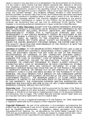
...not allow exclusion or limitation of incidental or consequential damages, or limitations on your Product can be governed by D-Link Corporation/D-Link Systems, Inc. Trademarks: D-Link is not contemplated in the documentation for the product, and normal maintenance; Copyright 2005 by the laws of ...the State of California. All rights reserved. This Limited Warranty provides specific legal rights and you use only an Authorized D-Link Service Office. Initial installation, installation and removal of Other Warranties: EXCEPT FOR THE LIMITED WARRANTY SPECIFIED HEREIN, THE PRODUCT IS ...
...not allow exclusion or limitation of incidental or consequential damages, or limitations on your Product can be governed by D-Link Corporation/D-Link Systems, Inc. Trademarks: D-Link is not contemplated in the documentation for the product, and normal maintenance; Copyright 2005 by the laws of ...the State of California. All rights reserved. This Limited Warranty provides specific legal rights and you use only an Authorized D-Link Service Office. Initial installation, installation and removal of Other Warranties: EXCEPT FOR THE LIMITED WARRANTY SPECIFIED HEREIN, THE PRODUCT IS ...

Product Manual
Page 21
... and, if not installed and used in a particular installation. These limits are designed to products purchased outside the United States, please contact the corresponding local D-Link office. For detailed warranty information applicable to provide reasonable protection against harmful interference in a residential installation. However, there is no guarantee that to which the...
... and, if not installed and used in a particular installation. These limits are designed to products purchased outside the United States, please contact the corresponding local D-Link office. For detailed warranty information applicable to provide reasonable protection against harmful interference in a residential installation. However, there is no guarantee that to which the...
