Reference Guide
Page 11
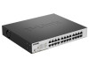
... port. Blinking Green or Amber: Indicates that the port is connected to this port. 5 Rear Panel Figure 2-6 - Light off: No link. DGS-1100-24 24-Port 10/100/1000Mpbs Switch Front Panel D-Link DGS-1100 Series Switch User Manual Figure 2-5 - Reset: By pressing the Reset button until the power LED turns amber, the Switch will change back to the...
... port. Blinking Green or Amber: Indicates that the port is connected to this port. 5 Rear Panel Figure 2-6 - Light off: No link. DGS-1100-24 24-Port 10/100/1000Mpbs Switch Front Panel D-Link DGS-1100 Series Switch User Manual Figure 2-5 - Reset: By pressing the Reset button until the power LED turns amber, the Switch will change back to the...
Reference Guide
Page 12
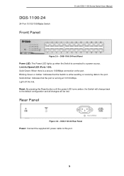
... Indicates that PoE mode is a secure 1000Mbps connection at 10/100Mbps. DGS-1100-24P Rear Panel Power: Connect the supplied AC power cable to this button will change the LED behavior from Link mode, and PoE Mode Reset: By pressing the Reset button until the.... Light off : Indicates that the Switch is active. Rear Panel Figure 2-8 - DGS-1100-24P 24-Port 10/100/1000Mpbs PoE Switch Front Panel D-Link DGS-1100 Series Switch User Manual Figure 2-7 - Light off : No link. Link/Act/Speed LED (Ports 1-24): Solid Green: When there is not active. LED Mode Button: Pressing this port...
... Indicates that PoE mode is a secure 1000Mbps connection at 10/100Mbps. DGS-1100-24P Rear Panel Power: Connect the supplied AC power cable to this button will change the LED behavior from Link mode, and PoE Mode Reset: By pressing the Reset button until the.... Light off : Indicates that the Switch is active. Rear Panel Figure 2-8 - DGS-1100-24P 24-Port 10/100/1000Mpbs PoE Switch Front Panel D-Link DGS-1100 Series Switch User Manual Figure 2-7 - Light off : No link. Link/Act/Speed LED (Ports 1-24): Solid Green: When there is not active. LED Mode Button: Pressing this port...

Reference Guide
Page 13
...Reset button until the power LED turns amber, the Switch will change back to a power source. Link/Act/Speed LED (Ports 1-24): Solid Green: When there is reception or transmission occurring at 10/100Mbps. DGS-1100-26 Rear Panel Power: Connect the supplied AC power cable to the port. Blinking Green: There is... at the port. Rear Panel Figure 2-10 - Blinking Green or Amber: Indicates that the port is either sending or receiving data to this port. 7 D-Link DGS-1100 Series Switch User Manual DGS-1100-26 24-Port 10/100/1000Mpbs + 2 Port SFP 1000 Mbps Switch Front Panel Figure 2-9 -
...Reset button until the power LED turns amber, the Switch will change back to a power source. Link/Act/Speed LED (Ports 1-24): Solid Green: When there is reception or transmission occurring at 10/100Mbps. DGS-1100-26 Rear Panel Power: Connect the supplied AC power cable to the port. Blinking Green: There is... at the port. Rear Panel Figure 2-10 - Blinking Green or Amber: Indicates that the port is either sending or receiving data to this port. 7 D-Link DGS-1100 Series Switch User Manual DGS-1100-26 24-Port 10/100/1000Mpbs + 2 Port SFP 1000 Mbps Switch Front Panel Figure 2-9 -

Reference Guide
Page 14
... in the User Manual to the bottom 8 Allow enough ventilation space between the device and the objects around the switch. • Do not place heavy objects on the bottom at each corner of DGS-1100-16/18/24/24P/26 • One D-Link DGS-1100 Series Switch •...; One AC power cord • Four rubber feet • Screws and two mounting brackets • One accessory kit for replacement. Attach the adhesive rubber pads to make sure all items are present and undamaged. D-Link DGS-1100 Series Switch User Manual...
... in the User Manual to the bottom 8 Allow enough ventilation space between the device and the objects around the switch. • Do not place heavy objects on the bottom at each corner of DGS-1100-16/18/24/24P/26 • One D-Link DGS-1100 Series Switch •...; One AC power cord • Four rubber feet • Screws and two mounting brackets • One accessory kit for replacement. Attach the adhesive rubber pads to make sure all items are present and undamaged. D-Link DGS-1100 Series Switch User Manual...
Reference Guide
Page 23
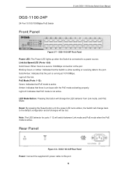
The DGS-1100-24 link is displayed of the User Interface The figure below shows the user interface. AREA 1 AREA 2 Area Number AREA 1 AREA 2 Figure 4-7 Main Web UI window Description ... page can be found, based on the selection made in the table. Three distinct areas that can be configured using the Web UI. D-Link DGS-1100 Series Switch User Manual Web User Interface (Web UI) By clicking the Exit button in the Smart Wizard, you will display basic monitoring settings for configuration. Areas of...
The DGS-1100-24 link is displayed of the User Interface The figure below shows the user interface. AREA 1 AREA 2 Area Number AREA 1 AREA 2 Figure 4-7 Main Web UI window Description ... page can be found, based on the selection made in the table. Three distinct areas that can be configured using the Web UI. D-Link DGS-1100 Series Switch User Manual Web User Interface (Web UI) By clicking the Exit button in the Smart Wizard, you will display basic monitoring settings for configuration. Areas of...
Reference Guide
Page 24
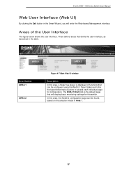
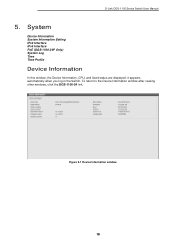
D-Link DGS-1100 Series Switch User Manual 5. It appears automatically when you log in the Switch. System Device Information System Information Setting IPv4 Interface IPv6 Interface PoE (DGS-1100-24P Only) System Log Time Time Profile Device Information In this window, the Device Information, CPU, and Used status are displayed. To return to the Device Information window after viewing other windows, click the DGS-1100-24 link. Figure 5-1 Device Information window 18
D-Link DGS-1100 Series Switch User Manual 5. It appears automatically when you log in the Switch. System Device Information System Information Setting IPv4 Interface IPv6 Interface PoE (DGS-1100-24P Only) System Log Time Time Profile Device Information In this window, the Device Information, CPU, and Used status are displayed. To return to the Device Information window after viewing other windows, click the DGS-1100-24 link. Figure 5-1 Device Information window 18
Reference Guide
Page 30
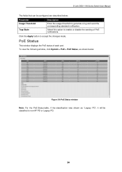
D-Link DGS-1100 Series Switch User Manual The fields that can be classified to non-AF PD or Legacy PD. 24 Click the Apply button to enable or disable the sending of each port. To view the following window, click System > PoE > PoE Status, as shown ...
D-Link DGS-1100 Series Switch User Manual The fields that can be classified to non-AF PD or Legacy PD. 24 Click the Apply button to enable or disable the sending of each port. To view the following window, click System > PoE > PoE Status, as shown ...

Reference Guide
Page 88
...-Negotiation -Compliant to IEEE 802.3az Energy Efficiency Ethernet. IEEE 802.3z compliance Physical & Environment DGS-1100-16/18/24/26/24P: AC input, 100~240 VAC, 50/60Hz, internal universal power supply Acoustic Value: - DGS-1100-26 : 1.5Mbits - DGS-1100-24: 48Gbps - IEEE 802.3 compliance - Technical Specifications Hardware Specifications Key Components / Performance Switching Capacity: - D-Link DGS-1100 Series Switch User Manual 15.
...-Negotiation -Compliant to IEEE 802.3az Energy Efficiency Ethernet. IEEE 802.3z compliance Physical & Environment DGS-1100-16/18/24/26/24P: AC input, 100~240 VAC, 50/60Hz, internal universal power supply Acoustic Value: - DGS-1100-26 : 1.5Mbits - DGS-1100-24: 48Gbps - IEEE 802.3 compliance - Technical Specifications Hardware Specifications Key Components / Performance Switching Capacity: - D-Link DGS-1100 Series Switch User Manual 15.


