Reference Guide
Page 3
Product Introduction...3 DGS-1100-16 ...3 Front Panel ...3 Rear Panel ...3 DGS-1100-18 ...4 Front Panel ...4 Rear Panel ...4 DGS-1100-24 ...5 Front Panel ...5 Rear Panel ...5 DGS-1100-24P ...6 Front Panel ...6 Rear Panel ...6 DGS-1100-26 ...7 Front Panel ...7 Rear Panel ...7 3. Web-based ... Interface ...20 Port Configuration ...20 Port Settings ...20 iii Hardware Installation ...8 Step 1: Unpacking...8 Packing contents of DGS-1100-16/18/24/24P/26 ...8 Step 2: Switch Installation ...8 Desktop or Shelf Installation ...8 Rack Installation ...9 Step 3 - Introduction ...1 Audience ...1 Other ...
Product Introduction...3 DGS-1100-16 ...3 Front Panel ...3 Rear Panel ...3 DGS-1100-18 ...4 Front Panel ...4 Rear Panel ...4 DGS-1100-24 ...5 Front Panel ...5 Rear Panel ...5 DGS-1100-24P ...6 Front Panel ...6 Rear Panel ...6 DGS-1100-26 ...7 Front Panel ...7 Rear Panel ...7 3. Web-based ... Interface ...20 Port Configuration ...20 Port Settings ...20 iii Hardware Installation ...8 Step 1: Unpacking...8 Packing contents of DGS-1100-16/18/24/24P/26 ...8 Step 2: Switch Installation ...8 Desktop or Shelf Installation ...8 Rack Installation ...9 Step 3 - Introduction ...1 Audience ...1 Other ...

Reference Guide
Page 4
... Detection ...50 Link Aggregation ...52 L2 Multicast Control ...55 IGMP Snooping ...55 Multicast Filtering ...57 LLDP ...58 LLDP Global Settings ...58 LLDP Neighbor Port Information ...58 8. Quality of Service (QoS) ...59 iv DGS-1100 Series Switch Web UI Reference Guide Jumbo Frame...21 PoE (DGS-1100-24P Only)...23 PoE System ...23 PoE Status ...24 PoE Configuration... 6. Management ...31 User Account Settings ...31 SNMP...32 SNMP Global Settings ...33 SNMP Community Table Settings ...33 SNMP Host Table Settings ...34 HTTP/HTTPS ...35 D-Link Discovery Protocol...35 7.
... Detection ...50 Link Aggregation ...52 L2 Multicast Control ...55 IGMP Snooping ...55 Multicast Filtering ...57 LLDP ...58 LLDP Global Settings ...58 LLDP Neighbor Port Information ...58 8. Quality of Service (QoS) ...59 iv DGS-1100 Series Switch Web UI Reference Guide Jumbo Frame...21 PoE (DGS-1100-24P Only)...23 PoE System ...23 PoE Status ...24 PoE Configuration... 6. Management ...31 User Account Settings ...31 SNMP...32 SNMP Global Settings ...33 SNMP Community Table Settings ...33 SNMP Host Table Settings ...34 HTTP/HTTPS ...35 D-Link Discovery Protocol...35 7.
Reference Guide
Page 11
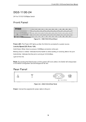
...By pressing the Reset button until the power LED turns amber, the Switch will change back to this port. 5 Light off: No link. DGS-1100-24 Front Panel Power LED: The Power LED lights up when the Switch is either sending or receiving data to a power source.... DGS-1100-24 Rear Panel Power: Connect the supplied AC power cable to the default configuration and all changes will be lost. Blinking Green or Amber: Indicates that the port is a secure 1000Mbps connection at 10/100 Mbps. DGS-1100-24 24-Port 10/100/1000Mpbs Switch Front Panel D-Link DGS-1100 Series Switch User...
...By pressing the Reset button until the power LED turns amber, the Switch will change back to this port. 5 Light off: No link. DGS-1100-24 Front Panel Power LED: The Power LED lights up when the Switch is either sending or receiving data to a power source.... DGS-1100-24 Rear Panel Power: Connect the supplied AC power cable to the default configuration and all changes will be lost. Blinking Green or Amber: Indicates that the port is a secure 1000Mbps connection at 10/100 Mbps. DGS-1100-24 24-Port 10/100/1000Mpbs Switch Front Panel D-Link DGS-1100 Series Switch User...
Reference Guide
Page 12
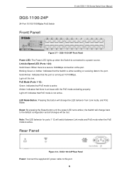
DGS-1100-24P 24-Port 10/100/1000Mpbs PoE Switch Front Panel D-Link DGS-1100 Series Switch User Manual Figure 2-7 - Blinking Green or Amber: Indicates that the Switch is not active. Solid Amber: Indicates that PoE mode is either sending ... is running at the port. Link/Act/Speed LED (Ports 1-24): Solid Green: When there is connected to this button will change back to the port. LED Mode Button: Pressing this port. 6 Rear Panel Figure 2-8 - DGS-1100-24P Rear Panel Power: Connect the supplied AC power cable to a power source. DGS-1100-24P Front Panel Power LED: The...
DGS-1100-24P 24-Port 10/100/1000Mpbs PoE Switch Front Panel D-Link DGS-1100 Series Switch User Manual Figure 2-7 - Blinking Green or Amber: Indicates that the Switch is not active. Solid Amber: Indicates that PoE mode is either sending ... is running at the port. Link/Act/Speed LED (Ports 1-24): Solid Green: When there is connected to this button will change back to the port. LED Mode Button: Pressing this port. 6 Rear Panel Figure 2-8 - DGS-1100-24P Rear Panel Power: Connect the supplied AC power cable to a power source. DGS-1100-24P Front Panel Power LED: The...

Reference Guide
Page 13
...: There is running at the port. DGS-1100-26 Rear Panel Power: Connect the supplied AC power cable to the default configuration and all changes will be lost. Light off : No link. Light off : No link. D-Link DGS-1100 Series Switch User Manual DGS-1100-26 24-Port 10/100/1000Mpbs + 2 Port ...SFP 1000 Mbps Switch Front Panel Figure 2-9 - DGS-1100-26 Front Panel Power LED: The Power LED lights up when ...
...: There is running at the port. DGS-1100-26 Rear Panel Power: Connect the supplied AC power cable to the default configuration and all changes will be lost. Light off : No link. Light off : No link. D-Link DGS-1100 Series Switch User Manual DGS-1100-26 24-Port 10/100/1000Mpbs + 2 Port ...SFP 1000 Mbps Switch Front Panel Figure 2-9 - DGS-1100-26 Front Panel Power LED: The Power LED lights up when ...

Reference Guide
Page 14
...between the device and the objects around the switch. • Do not place heavy objects on the bottom at each corner of DGS-1100-16/18/24/24P/26 • One D-Link DGS-1100 Series Switch • One AC power cord • Four rubber feet • Screws and two mounting brackets • One..., please contact your local D-Link reseller for a ground screw • One Multi-lingual Getting Started Guide • One CD with the device must be attached on the switch. Attach the adhesive rubber pads to make sure all items are present and undamaged. D-Link DGS-1100 Series Switch User Manual 3....
...between the device and the objects around the switch. • Do not place heavy objects on the bottom at each corner of DGS-1100-16/18/24/24P/26 • One D-Link DGS-1100 Series Switch • One AC power cord • Four rubber feet • Screws and two mounting brackets • One..., please contact your local D-Link reseller for a ground screw • One Multi-lingual Getting Started Guide • One CD with the device must be attached on the switch. Attach the adhesive rubber pads to make sure all items are present and undamaged. D-Link DGS-1100 Series Switch User Manual 3....
Reference Guide
Page 23
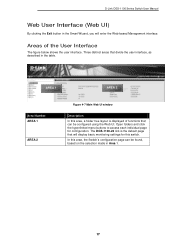
...Web UI window Description In this area, a folder tree layout is the default page that can be configured using the Web UI. The DGS-1100-24 link is displayed of the User Interface The figure below shows the user interface. In this switch. Open folders and click the hyperlinked menu ... configuration page can be found, based on the selection made in the Smart Wizard, you will display basic monitoring settings for configuration. D-Link DGS-1100 Series Switch User Manual Web User Interface (Web UI) By clicking the Exit button in Area 1. 17 Three distinct areas that divide ...
...Web UI window Description In this area, a folder tree layout is the default page that can be configured using the Web UI. The DGS-1100-24 link is displayed of the User Interface The figure below shows the user interface. In this switch. Open folders and click the hyperlinked menu ... configuration page can be found, based on the selection made in the Smart Wizard, you will display basic monitoring settings for configuration. D-Link DGS-1100 Series Switch User Manual Web User Interface (Web UI) By clicking the Exit button in Area 1. 17 Three distinct areas that divide ...
Reference Guide
Page 24
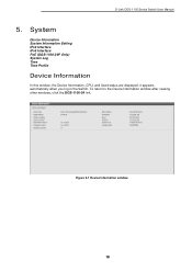
To return to the Device Information window after viewing other windows, click the DGS-1100-24 link. Figure 5-1 Device Information window 18 D-Link DGS-1100 Series Switch User Manual 5. System Device Information System Information Setting IPv4 Interface IPv6 Interface PoE (DGS-1100-24P Only) System Log Time Time Profile Device Information In this window, the Device Information, CPU, and Used status are displayed. It appears automatically when you log in the Switch.
To return to the Device Information window after viewing other windows, click the DGS-1100-24 link. Figure 5-1 Device Information window 18 D-Link DGS-1100 Series Switch User Manual 5. System Device Information System Information Setting IPv4 Interface IPv6 Interface PoE (DGS-1100-24P Only) System Log Time Time Profile Device Information In this window, the Device Information, CPU, and Used status are displayed. It appears automatically when you log in the Switch.
Reference Guide
Page 30
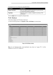
... will be configured are described below: Parameter Usage Threshold Trap State Description Enter the usage threshold to generate a log and send the corresponding standard notification. D-Link DGS-1100 Series Switch User Manual The fields that can be classified to non-AF PD or Legacy PD...
... will be configured are described below: Parameter Usage Threshold Trap State Description Enter the usage threshold to generate a log and send the corresponding standard notification. D-Link DGS-1100 Series Switch User Manual The fields that can be classified to non-AF PD or Legacy PD...

Reference Guide
Page 88
... IGMP Snooping VLAN 802.1Q VLAN standard Port-Based VLAN 82 D-Link DGS-1100 Series Switch User Manual 15. DGS-1100-18: 36Gbps - DGS-1100-24P : 48Gbps Max. DGS-1100-18: 26.79Mpps - DGS-1100-26 : 1.5Mbits - IEEE 802.3 compliance - IEEE 802.3u compliance - IEEE 802.3ab compliance - IEEE802.3at (Only DGS-1100-24 Port 1 ~ Port 12) -Supports Full/half-Duplex operations at 10/100Mbps...
... IGMP Snooping VLAN 802.1Q VLAN standard Port-Based VLAN 82 D-Link DGS-1100 Series Switch User Manual 15. DGS-1100-18: 36Gbps - DGS-1100-24P : 48Gbps Max. DGS-1100-18: 26.79Mpps - DGS-1100-26 : 1.5Mbits - IEEE 802.3 compliance - IEEE 802.3u compliance - IEEE 802.3ab compliance - IEEE802.3at (Only DGS-1100-24 Port 1 ~ Port 12) -Supports Full/half-Duplex operations at 10/100Mbps...


