
Manual
Page 2
... List ...15 About ...15 Device Configuration...15 i D-Link EasySmart Switch User Manual Table of Contents Table of Contents ...i About This Guide ...1 Terms/Usage...1 Copyright and Trademarks ...1 1 Product Introduction ...2 DGS-1100-05 ...2 Front Panel ...2 Rear Panel...2 DGS-1100-08 ...2 Front Panel ...3 Rear Panel...3 DGS-1100-08P...3 Front Panel ...3 Rear Panel...4 DGS-1100-16 ...4 Front Panel ...4 Rear Panel...5 DGS-1100-24 ...5 Front Panel ...5 Rear Panel...5 2 Hardware...
... List ...15 About ...15 Device Configuration...15 i D-Link EasySmart Switch User Manual Table of Contents Table of Contents ...i About This Guide ...1 Terms/Usage...1 Copyright and Trademarks ...1 1 Product Introduction ...2 DGS-1100-05 ...2 Front Panel ...2 Rear Panel...2 DGS-1100-08 ...2 Front Panel ...3 Rear Panel...3 DGS-1100-08P...3 Front Panel ...3 Rear Panel...4 DGS-1100-16 ...4 Front Panel ...4 Rear Panel...5 DGS-1100-24 ...5 Front Panel ...5 Rear Panel...5 2 Hardware...

Manual
Page 3
D-Link EasySmart Switch User Manual Add (+), Delete (-) and Discover the device 17 Device List...18 5 Configuration ...19 Web-based Management...19 Tool Bar > Save Menu ...20 Save ...> Static MAC 35 Security > MAC Address Table > Dynamic Forwarding Table 36 PoE > PoE Global Settings (DGS-1100-08P only 37 PoE > PoE Port Settings (DGS-1100-08P only 38 Appendix A - Ethernet Technology...40 Gigabit Ethernet Technology ...40 Fast Ethernet Technology ...40 Switching Technology ...40 Appendix B - Technical Specifications ...41 Hardware Specifications ...41 Key Components / Performance ...41 Port ...
D-Link EasySmart Switch User Manual Add (+), Delete (-) and Discover the device 17 Device List...18 5 Configuration ...19 Web-based Management...19 Tool Bar > Save Menu ...20 Save ...> Static MAC 35 Security > MAC Address Table > Dynamic Forwarding Table 36 PoE > PoE Global Settings (DGS-1100-08P only 37 PoE > PoE Port Settings (DGS-1100-08P only 38 Appendix A - Ethernet Technology...40 Gigabit Ethernet Technology ...40 Fast Ethernet Technology ...40 Switching Technology ...40 Appendix B - Technical Specifications ...41 Hardware Specifications ...41 Key Components / Performance ...41 Port ...

Manual
Page 5
.... Smart Console Utility: An introduction to terms "switch", "bridge" and "switching hubs" interchangeably, and both are commonly accepted for Ethernet switches. Some technologies refer to the central management system. 4. D-Link EasySmart Switch User Manual About This Guide This guide provides instructions to install the D-Link Gigabit Ethernet EasySmart Switch DGS-110005/08/08P/16/24, how to use of the device...
.... Smart Console Utility: An introduction to terms "switch", "bridge" and "switching hubs" interchangeably, and both are commonly accepted for Ethernet switches. Some technologies refer to the central management system. 4. D-Link EasySmart Switch User Manual About This Guide This guide provides instructions to install the D-Link Gigabit Ethernet EasySmart Switch DGS-110005/08/08P/16/24, how to use of the device...

Manual
Page 6
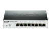
... servers, the network can reduce power consumption by detecting short cable and link-down devices. Once if a packet is connected to connect the 5V/1A AC adapter. DGS-1100-05 5-Port 10/100/1000Mpbs EasySmart Switch Front Panel Figure 1- DGS-1100-08 8-Port 10/100/1000Mpbs EasySmart Switch 2 Blinking: Indicates that the port is either sending or receiving data...
... servers, the network can reduce power consumption by detecting short cable and link-down devices. Once if a packet is connected to connect the 5V/1A AC adapter. DGS-1100-05 5-Port 10/100/1000Mpbs EasySmart Switch Front Panel Figure 1- DGS-1100-08 8-Port 10/100/1000Mpbs EasySmart Switch 2 Blinking: Indicates that the port is either sending or receiving data...
Manual
Page 7
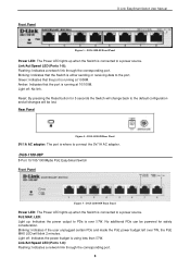
..., the PoE MAX LED will be powered for 5 seconds the Switch will change back to PDs is running at 1000M. Light off : No link. DGS-1100-08 Front Panel Power LED: The Power LED lights up when the Switch is using less than 57W. Light off : Indicates the power ... where to a power source. No additional PDs can be lost. Amber: Indicates that the Switch is running at 10/100M. DGS-1100-08P 8-Port 10/100/1000Mpbs PoE EasySmart Switch Front Panel Figure 5 - DGS-1100-08P Front Panel Power LED: The Power LED lights up : Indicates the power output to the default configuration and ...
..., the PoE MAX LED will be powered for 5 seconds the Switch will change back to PDs is running at 1000M. Light off : No link. DGS-1100-08 Front Panel Power LED: The Power LED lights up when the Switch is using less than 57W. Light off : Indicates the power ... where to a power source. No additional PDs can be lost. Amber: Indicates that the Switch is running at 10/100M. DGS-1100-08P 8-Port 10/100/1000Mpbs PoE EasySmart Switch Front Panel Figure 5 - DGS-1100-08P Front Panel Power LED: The Power LED lights up : Indicates the power output to the default configuration and ...
Manual
Page 8
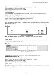
.... 3. DGS-1100-08P Rear Panel 48V/1.57A Desktop adapter: The port is where to : 1. Amber: Indicates that the port is running at 10/100M. Light off : No link. Rear Panel Figure 6 - DGS-1100-16 Front Panel Power LED: The Power LED lights up when the Switch is connected...1000M. Reset: By pressing the Reset button for 5 seconds the Switch will change back to a power source. Light off : No link. DGS-1100-16 16-Port 10/100/1000Mpbs EasySmart Switch Front Panel Figure 7 - Blinking: Indicates that the Switch is either sending or receiving data to the port. Green: ...
.... 3. DGS-1100-08P Rear Panel 48V/1.57A Desktop adapter: The port is where to : 1. Amber: Indicates that the port is running at 10/100M. Light off : No link. Rear Panel Figure 6 - DGS-1100-16 Front Panel Power LED: The Power LED lights up when the Switch is connected...1000M. Reset: By pressing the Reset button for 5 seconds the Switch will change back to a power source. Light off : No link. DGS-1100-16 16-Port 10/100/1000Mpbs EasySmart Switch Front Panel Figure 7 - Blinking: Indicates that the Switch is either sending or receiving data to the port. Green: ...

Manual
Page 9
... sending or receiving data to the default settings. Light off: No link. Blinking: Indicates that the Switch is connected to connect the AC power cord. Amber: Indicates that the port is running at 10/100M. DGS-1100-24 24-Port 10/100/1000Mpbs EasySmart Switch Front Panel Figure 9 - Green: Indicates that the port is running at...
... sending or receiving data to the default settings. Light off: No link. Blinking: Indicates that the Switch is connected to connect the AC power cord. Amber: Indicates that the port is running at 10/100M. DGS-1100-24 24-Port 10/100/1000Mpbs EasySmart Switch Front Panel Figure 9 - Green: Indicates that the port is running at...

Manual
Page 10
...kit for wall-mount installation One ground screw that screw on the D-Link EasySmart Switch One Multi-lingual Getting Started Guide One CD with User Manual and SmartConsole Utility program Packing contents of DGS-1100-08P One D-Link EasySmart Switch One Desktop Power Adapter One AC power cord Four rubber feet One ground...inspect the power cord to see that screw on the D-Link EasySmart Switch One Multi-lingual Getting Started Guide One CD with the device must be attached on the bottom at each corner of DGS-1100-16/24 One D-Link EasySmart Switch One AC power cord Four rubber feet Screws and two ...
...kit for wall-mount installation One ground screw that screw on the D-Link EasySmart Switch One Multi-lingual Getting Started Guide One CD with User Manual and SmartConsole Utility program Packing contents of DGS-1100-08P One D-Link EasySmart Switch One Desktop Power Adapter One AC power cord Four rubber feet One ground...inspect the power cord to see that screw on the D-Link EasySmart Switch One Multi-lingual Getting Started Guide One CD with the device must be attached on the bottom at each corner of DGS-1100-16/24 One D-Link EasySmart Switch One AC power cord Four rubber feet Screws and two ...

Manual
Page 11
... in a wiring closet with the maximum ambient temperature (Tma) specified by the manufacturer. 7 Therefore, consideration should be given to the bottom Rack Installation The switch can be mounted in an EIA standard size 11-inch rack, which can be placed in a closed or multi-unit rack assembly, the operating ambient... - Attach the adhesive rubber pads to installing the equipment in the rack or chassis Please be greater than room ambient. Figure 12 - Mount the Switch in an environment compatible with other equipment. D-Link EasySmart Switch User Manual Figure 11 - Figure 13-
... in a wiring closet with the maximum ambient temperature (Tma) specified by the manufacturer. 7 Therefore, consideration should be given to the bottom Rack Installation The switch can be mounted in an EIA standard size 11-inch rack, which can be placed in a closed or multi-unit rack assembly, the operating ambient... - Attach the adhesive rubber pads to installing the equipment in the rack or chassis Please be greater than room ambient. Figure 12 - Mount the Switch in an environment compatible with other equipment. D-Link EasySmart Switch User Manual Figure 11 - Figure 13-

Manual
Page 12
... safe operation of the circuits might have on a wood wall Step 1: Drive the T3 x 15L screws into the rear of the switch and to uneven mechanical loading. Step 2. D-Link EasySmart Switch User Manual B) Reduced Air Flow - Appropriate consideration of air flow required for this concern. Figure 14 -Wall mount installation Step 3 - E) Reliable Earthing - use...
... safe operation of the circuits might have on a wood wall Step 1: Drive the T3 x 15L screws into the rear of the switch and to uneven mechanical loading. Step 2. D-Link EasySmart Switch User Manual B) Reduced Air Flow - Appropriate consideration of air flow required for this concern. Figure 14 -Wall mount installation Step 3 - E) Reliable Earthing - use...

Manual
Page 13
...Step 4: Using a screwdriver, tighten the ground screw to secure the ground cable to ground. Grounding the Switch This section describes how to connect the EasySmart Switch to the switch. Step 2: Use the ground cable to place the #8 terminal lug ring on top of power failure. ...at the other end of the switch to proper grounding facilities. A screwdriver (not included in the accessory kit) The following steps let you connect the switch to 6 AWG copper conductor is installed. D-Link EasySmart Switch User Manual Figure 15 -Plugging the switch into the ground-screw opening ...
...Step 4: Using a screwdriver, tighten the ground screw to secure the ground cable to ground. Grounding the Switch This section describes how to connect the EasySmart Switch to the switch. Step 2: Use the ground cable to place the #8 terminal lug ring on top of power failure. ...at the other end of the switch to proper grounding facilities. A screwdriver (not included in the accessory kit) The following steps let you connect the switch to 6 AWG copper conductor is installed. D-Link EasySmart Switch User Manual Figure 15 -Plugging the switch into the ground-screw opening ...

Manual
Page 14
... Connect the Ethernet cable to any PC using the SmartConsole Utility, you want to manage multiple D-Link EasySmart Switches, the SmartConsole Utility is a more convenient choice. Each switch must be managed through any of the ports on the PC. 10 The PC should be in... the Web-Based Management at a time. D-Link EasySmart Switch User Manual 3 Getting Started This chapter introduces the management interface of the switch and to the Ethernet port on the front panel of D-Link EasySmart Switch. Management Options The D-Link EasySmart Switch can allow only one user to access to...
... Connect the Ethernet cable to any PC using the SmartConsole Utility, you want to manage multiple D-Link EasySmart Switches, the SmartConsole Utility is a more convenient choice. Each switch must be managed through any of the ports on the PC. 10 The PC should be in... the Web-Based Management at a time. D-Link EasySmart Switch User Manual 3 Getting Started This chapter introduces the management interface of the switch and to the Ethernet port on the front panel of D-Link EasySmart Switch. Management Options The D-Link EasySmart Switch can allow only one user to access to...

Manual
Page 15
... default password is a number between 0 ~ 254 and z is admin. Figure 19 - D-Link EasySmart Switch User Manual Figure 17 -Connected Ethernet cable Login Web-based Management In order to login and configure the switch via an Ethernet connection, the PC must have an IP address of 10.x.y.z (where x/y is... Utility. Logon Dialog Box SmartConsole Utility The SmartConsole Utility included in your PC. There are two options for discovering D-Link Smart Switches and EasySmart Switches within the same L2 network segment connected to your web browser. Figure 18 -Enter the IP address 10.90.90...
... default password is a number between 0 ~ 254 and z is admin. Figure 19 - D-Link EasySmart Switch User Manual Figure 17 -Connected Ethernet cable Login Web-based Management In order to login and configure the switch via an Ethernet connection, the PC must have an IP address of 10.x.y.z (where x/y is... Utility. Logon Dialog Box SmartConsole Utility The SmartConsole Utility included in your PC. There are two options for discovering D-Link Smart Switches and EasySmart Switches within the same L2 network segment connected to your web browser. Figure 18 -Enter the IP address 10.90.90...

Manual
Page 16
... folder. Double click on you through the process. 4. Follow the on the Drive to open the utility by clicking Start > Programs > D-Link SmartConsole Utility. 5. Upon completion, go to install the utility. 5. Option 1: Follow these steps to install the SmartConsole Utility via the autorun ...the latest SmartConsole Utility. For detailed explanations of your PC and use the SmartConsole Utility to discover the Smart Switches. Click on the installation CD. 1. D-Link EasySmart Switch User Manual NOTE: Please be sure to uninstall any existing SmartConsole Utility from your PC and use the ...
... folder. Double click on you through the process. 4. Follow the on the Drive to open the utility by clicking Start > Programs > D-Link SmartConsole Utility. 5. Upon completion, go to install the utility. 5. Option 1: Follow these steps to install the SmartConsole Utility via the autorun ...the latest SmartConsole Utility. For detailed explanations of your PC and use the SmartConsole Utility to discover the Smart Switches. Click on the installation CD. 1. D-Link EasySmart Switch User Manual NOTE: Please be sure to uninstall any existing SmartConsole Utility from your PC and use the ...

Manual
Page 17
Utility Group Interval establishes the intervals (in seconds) that the Switch will be discovered in the same domain of the PC, collect traps and log messages, and quick access to launch the Utility Settings ... secs, 30 secs, 1mins, 2mins, and 5 mins for selecting the monitoring time intervals. Figure 21- D-Link EasySmart Switch User Manual 4 SmartConsole Utility The D-Link SmartConsole Utility allows the administrator to quickly discover all D-Link Smart Switches and EasySmart Switches which were selected as the main body, and SmartConsole Settings at the left . Refresh time refreshes the...
Utility Group Interval establishes the intervals (in seconds) that the Switch will be discovered in the same domain of the PC, collect traps and log messages, and quick access to launch the Utility Settings ... secs, 30 secs, 1mins, 2mins, and 5 mins for selecting the monitoring time intervals. Figure 21- D-Link EasySmart Switch User Manual 4 SmartConsole Utility The D-Link SmartConsole Utility allows the administrator to quickly discover all D-Link Smart Switches and EasySmart Switches which were selected as the main body, and SmartConsole Settings at the left . Refresh time refreshes the...

Manual
Page 18
...Click Clear Log to clear all log entries. Click Clear Trap to clear all entries. SmartConsole Trap The trap icon in the Switch or the switches will not be disabled in the SmartConsole Settings will change while receiving new trap messages. Please see below for detailed description. Click ...of this trap message. Date/Time indicates when the message was received 14 Figure 22- Log Click this icon to exit Figure 53 - D-Link EasySmart Switch User Manual NOTE: If the Group Interval is set to 0, IGMP Snooping must be discovered. Icon Description No new traps New traps was ...
...Click Clear Log to clear all log entries. Click Clear Trap to clear all entries. SmartConsole Trap The trap icon in the Switch or the switches will not be disabled in the SmartConsole Settings will change while receiving new trap messages. Please see below for detailed description. Click ...of this trap message. Date/Time indicates when the message was received 14 Figure 22- Log Click this icon to exit Figure 53 - D-Link EasySmart Switch User Manual NOTE: If the Group Interval is set to 0, IGMP Snooping must be discovered. Icon Description No new traps New traps was ...

Manual
Page 19
... 25- Monitor Save As: Records the setting of the Device List as default for the Device List. Device Settings Select a switch from the Device List. Here you will see below options: D-Link EasySmart Switch User Manual Figure 24- Monitor List By clicking on this icon to launch the SmartConsole Info window. SmartConsole Monitor List...
... 25- Monitor Save As: Records the setting of the Device List as default for the Device List. Device Settings Select a switch from the Device List. Here you will see below options: D-Link EasySmart Switch User Manual Figure 24- Monitor List By clicking on this icon to launch the SmartConsole Info window. SmartConsole Monitor List...

Manual
Page 20
... the devices and SmartConsole Utility. Specify the Firmware Path (or Browse for any reason. 16 SmartConsole Device Settings NOTE: The EasySmart Switch automatically sends out discovery packets to launch the Firmware Upgrade window. Here you are going to configure the Group Interval setting. ... "OK" after completion, and "Fail" is firmware upgrade fails or cannot be completed for one or many switches of device, and then click Upgrade. D-Link EasySmart Switch User Manual To apply the configuration, insert the correct device password in the Confirm Password box and then click ...
... the devices and SmartConsole Utility. Specify the Firmware Path (or Browse for any reason. 16 SmartConsole Device Settings NOTE: The EasySmart Switch automatically sends out discovery packets to launch the Firmware Upgrade window. Here you are going to configure the Group Interval setting. ... "OK" after completion, and "Fail" is firmware upgrade fails or cannot be completed for one or many switches of device, and then click Upgrade. D-Link EasySmart Switch User Manual To apply the configuration, insert the correct device password in the Confirm Password box and then click ...

Manual
Page 21
...to display all the Web Smart and EasySmart switches located in the same domain with the management PC. The device will renew the IP address from the Device List. DHCP Refresh Web Access Select a switch from the DHCP server. Here you can configure the Switch through the Web-based Management utility.... by double-clicking the device in the Device List shows the default IP is still used, it . D-Link EasySmart Switch User Manual Figure 28 -Firmware Upgrade DHCP Refresh: If a DHCP-client enabled switch in the device list. You may also get into Discover List, or select a device and click the ...
...to display all the Web Smart and EasySmart switches located in the same domain with the management PC. The device will renew the IP address from the Device List. DHCP Refresh Web Access Select a switch from the DHCP server. Here you can configure the Switch through the Web-based Management utility.... by double-clicking the device in the Device List shows the default IP is still used, it . D-Link EasySmart Switch User Manual Figure 28 -Firmware Upgrade DHCP Refresh: If a DHCP-client enabled switch in the device list. You may also get into Discover List, or select a device and click the ...

Manual
Page 22
... IP: Displays the IP address of this device. SmartConsole Delete device Device List This list displays all discovered Web Smart and EasySmart switches on the network. When the device was discovered by SmartConsole. System Name: Displays the appointed device system name. Gateway: Displays... cable of host where the Trap information will change to have the device keep updating the information, The icon will become . D-Link EasySmart Switch User Manual Figure 6- Click the icon to . Location: Displays where the appointed device location. SNMP: Displays the SNMP status of...
... IP: Displays the IP address of this device. SmartConsole Delete device Device List This list displays all discovered Web Smart and EasySmart switches on the network. When the device was discovered by SmartConsole. System Name: Displays the appointed device system name. Gateway: Displays... cable of host where the Trap information will change to have the device keep updating the information, The icon will become . D-Link EasySmart Switch User Manual Figure 6- Click the icon to . Location: Displays where the appointed device location. SNMP: Displays the SNMP status of...

