Product Manual
Page 2
... TECHNOLOGY...1 GIGABIT ETHERNET TECHNOLOGY ...1 SWITCHING TECHNOLOGY ...2 FEATURES ...2 Chassis ...2 Modules...3 CPU Module ...3 10BASE-T/100BASE-TX Module...3 100BASE-FX (MT-RJ) Module...4 1000BASE-T (RJ-45) Module ...4 1000BASE-SX (SC) Module ...4 1000BASE-LX (SC) Module ...4 Power Supply Modules ...4 UNPACKING AND SETUP...6 UNPACKING...SC) Gigabit Module...14 1000BASE-LX (SC) Gigabit Module ...14 Power Supply Modules ...15 LED INDICATORS ...15 CONNECTING THE SWITCH ...16 SWITCH TO END NODE ...16 SWITCH TO HUB OR SWITCH ...16 10BASE-T Device ...17 100BASE-TX Device ...17 1000BASE-T Device...
... TECHNOLOGY...1 GIGABIT ETHERNET TECHNOLOGY ...1 SWITCHING TECHNOLOGY ...2 FEATURES ...2 Chassis ...2 Modules...3 CPU Module ...3 10BASE-T/100BASE-TX Module...3 100BASE-FX (MT-RJ) Module...4 1000BASE-T (RJ-45) Module ...4 1000BASE-SX (SC) Module ...4 1000BASE-LX (SC) Module ...4 Power Supply Modules ...4 UNPACKING AND SETUP...6 UNPACKING...SC) Gigabit Module...14 1000BASE-LX (SC) Gigabit Module ...14 Power Supply Modules ...15 LED INDICATORS ...15 CONNECTING THE SWITCH ...16 SWITCH TO END NODE ...16 SWITCH TO HUB OR SWITCH ...16 10BASE-T Device ...17 100BASE-TX Device ...17 1000BASE-T Device...
Product Manual
Page 7
... development pushing the limits of Ethernet technology is automatically forwarded by higher latencies. Traffic that modules and power supplies are an ideal solution to most kinds of local area network congestion problems. Features The DES-6000 Modular switch is designed for the next generation of increasing the total network capacity available to another (from one...
... development pushing the limits of Ethernet technology is automatically forwarded by higher latencies. Traffic that modules and power supplies are an ideal solution to most kinds of local area network congestion problems. Features The DES-6000 Modular switch is designed for the next generation of increasing the total network capacity available to another (from one...
Product Manual
Page 9
...duplex ♦ Per port packet buffer: 0.5 Mbytes 1000BASE-T (RJ-45) Module ♦ 2-port, front-panel module ♦ Store and forward packet switching ♦ Connects to 1000BASE-T devices only at full-duplex and auto-negotiating. ♦ 2 1000BASE-T (RJ-45) Gigabit Ethernet ports ♦ Fully ...Support Full-duplex operation only ♦ IEEE 802.3x-compliant Flow Control support ♦ Per port packet buffer: 2 Mbytes Power Supply Modules ♦ Dual power modules design ♦ Current sharing design ♦ Full redundant feature design to ensure continuous operation ♦ If one...
...duplex ♦ Per port packet buffer: 0.5 Mbytes 1000BASE-T (RJ-45) Module ♦ 2-port, front-panel module ♦ Store and forward packet switching ♦ Connects to 1000BASE-T devices only at full-duplex and auto-negotiating. ♦ 2 1000BASE-T (RJ-45) Gigabit Ethernet ports ♦ Fully ...Support Full-duplex operation only ♦ IEEE 802.3x-compliant Flow Control support ♦ Per port packet buffer: 2 Mbytes Power Supply Modules ♦ Dual power modules design ♦ Current sharing design ♦ Full redundant feature design to ensure continuous operation ♦ If one...
Product Manual
Page 11
... contain the following steps: ♦ The surface must support at least 5 kg. ♦ The power outlet should be performed using the following items: ♦ One switch chassis ♦ One management module (pre-installed in uppermost slot) ♦ One power supply module (pre-installed) ♦ One mounting kit: four mounting brackets and screws ♦ Four...
... contain the following steps: ♦ The surface must support at least 5 kg. ♦ The power outlet should be performed using the following items: ♦ One switch chassis ♦ One management module (pre-installed in uppermost slot) ♦ One power supply module (pre-installed) ♦ One mounting kit: four mounting brackets and screws ♦ Four...
Product Manual
Page 13
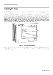
.... After warmswapping a networking module, the switch will automatically be installed into any free slot, except the CPU module which can be rebooted. Further, make sure you have unplugged the power cord from the removable power supply module before warm-swapping modules. Removing or... inserting the CPU module while the power is on may be installed in place. 8 Unpacking and Setup Modular Ethernet Switch User's Guide Installing Modules The DES-6000 supports up to 9...
.... After warmswapping a networking module, the switch will automatically be installed into any free slot, except the CPU module which can be rebooted. Further, make sure you have unplugged the power cord from the removable power supply module before warm-swapping modules. Removing or... inserting the CPU module while the power is on may be installed in place. 8 Unpacking and Setup Modular Ethernet Switch User's Guide Installing Modules The DES-6000 supports up to 9...
Product Manual
Page 14
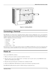
... is operating correctly. Observe the DES-6000's LED indicators to make sure the Switch is properly installed in the device. 2. Power on the DES-6000's front panel of the redundant power supply. 3. Plug the outlet end of the supplied power cord firmly into a suitable AC outlet. 4. The DES-6000's LED indicators operate as follows during a normal power-up the DES-6000 as follows: ♦ Baud...
... is operating correctly. Observe the DES-6000's LED indicators to make sure the Switch is properly installed in the device. 2. Power on the DES-6000's front panel of the redundant power supply. 3. Plug the outlet end of the supplied power cord firmly into a suitable AC outlet. 4. The DES-6000's LED indicators operate as follows during a normal power-up the DES-6000 as follows: ♦ Baud...

Product Manual
Page 16
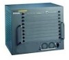
...module slots installing networking modules and the CPU module. ♦ Two slide-in module slots for power supply modules, an RS-232 communication port, and LED indicators. Modular Ethernet Switch User's Guide 3 IDENTIFYING EXTERNAL COMPONENTS This chapter describes the front panel, side panels, optional ... for networking modules, two slide-in module slots for installing power supply modules. Front panel view of the Switch ♦ Comprehensive LED indicators display the conditions of the Switch and status of the Switch contains four system fans. Be reminded that without proper heat ...
...module slots installing networking modules and the CPU module. ♦ Two slide-in module slots for power supply modules, an RS-232 communication port, and LED indicators. Modular Ethernet Switch User's Guide 3 IDENTIFYING EXTERNAL COMPONENTS This chapter describes the front panel, side panels, optional ... for networking modules, two slide-in module slots for installing power supply modules. Front panel view of the Switch ♦ Comprehensive LED indicators display the conditions of the Switch and status of the Switch contains four system fans. Be reminded that without proper heat ...
Product Manual
Page 20
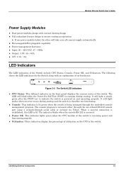
... utilization on and operating properly. The console program is being managed through serial cable or in the switch. Identifying External Components 15 Modular Ethernet Switch User's Guide Power Supply Modules ♦ Dual power modules design with an explanation of the Switch include CPU Status, Console, Power OK, and Utilization. The following shows the LED indicators for the...
... utilization on and operating properly. The console program is being managed through serial cable or in the switch. Identifying External Components 15 Modular Ethernet Switch User's Guide Power Supply Modules ♦ Dual power modules design with an explanation of the Switch include CPU Status, Console, Power OK, and Utilization. The following shows the LED indicators for the...
Product Manual
Page 26
... a redundant power supply module is installed in the switch. ♦ Power Supply Module Removed This trap is sent whenever a redundant power supply module is removed in the switch. ♦ Bad Power This trap is sent whenever a redundant power supply is receiving AC power but not supplying DC power to browse or modify MIBs, you use a third-party vendors' SNMP software to link up to link down...
... a redundant power supply module is installed in the switch. ♦ Power Supply Module Removed This trap is sent whenever a redundant power supply module is removed in the switch. ♦ Bad Power This trap is sent whenever a redundant power supply is receiving AC power but not supplying DC power to browse or modify MIBs, you use a third-party vendors' SNMP software to link up to link down...
Product Manual
Page 44
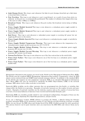
... Management System or to be assigned on the System Configuration menu. Should be of the form xxx.xxx.xxx.xxx, where each xxx is powered up. These fields should be a unique address on . The same IP address is shared by both the SLIP and Ethernet network interfaces....used on your network. ♦ IP Address Determines the IP address used by the Switch. See the next chapter for receiving SNMP and Telnet communications. Choose Configure IP Address to access the Switch using the supplied settings. BootP - The BOOTP protocol allows IP addresses, network masks, and default ...
... Management System or to be assigned on the System Configuration menu. Should be of the form xxx.xxx.xxx.xxx, where each xxx is powered up. These fields should be a unique address on . The same IP address is shared by both the SLIP and Ethernet network interfaces....used on your network. ♦ IP Address Determines the IP address used by the Switch. See the next chapter for receiving SNMP and Telnet communications. Choose Configure IP Address to access the Switch using the supplied settings. BootP - The BOOTP protocol allows IP addresses, network masks, and default ...
Product Manual
Page 80
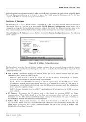
Modular Ethernet Switch User's Guide Figure 6-62. Figure 6-63. From this screen you to view the following table: Using the Console Interface 75 Device Status screen Browse GVRP Status Selecting Browse GVRP Status allows you can activate or deactivate the buzzer. Device Status Selecting Device Status will display power supply and fan status. Switch History screen The switch history entries are listed chronologically from the last time the Switch was rebooted.
Modular Ethernet Switch User's Guide Figure 6-62. Figure 6-63. From this screen you to view the following table: Using the Console Interface 75 Device Status screen Browse GVRP Status Selecting Browse GVRP Status allows you can activate or deactivate the buzzer. Device Status Selecting Device Status will display power supply and fan status. Switch History screen The switch history entries are listed chronologically from the last time the Switch was rebooted.
Product Manual
Page 120
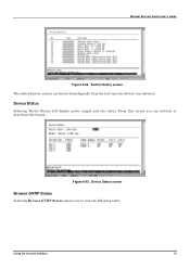
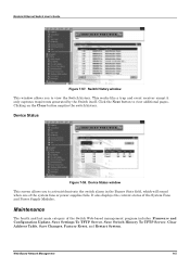
...trap/events generated by the Switch itself. Device Status Figure 7-58. Device Status window This screen allows you to activate/deacivate the switch alarm in the Buzzer State field, which will sound when one of the system fans or power supplies fails. Switch History window This window ...allows you to view the Switch history. Click the Next button to view additional pages....
...trap/events generated by the Switch itself. Device Status Figure 7-58. Device Status window This screen allows you to activate/deacivate the switch alarm in the Buzzer State field, which will sound when one of the system fans or power supplies fails. Switch History window This window ...allows you to view the Switch history. Click the Next button to view additional pages....
Product Manual
Page 126
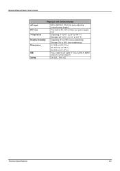
Modular Ethernet Switch User's Guide Physical and Environmental AC Input DC Fans Temperature Relative Humidity Dimensions EMI Safety 90 to 264 VAC, 47-63 Hz (auto-adjusting internal power supply) Two built-in 60 x 60 mm fans per power supply unit Operating: 0° to 40° C (32° to 104° F) Storage: -25° to 55...
Modular Ethernet Switch User's Guide Physical and Environmental AC Input DC Fans Temperature Relative Humidity Dimensions EMI Safety 90 to 264 VAC, 47-63 Hz (auto-adjusting internal power supply) Two built-in 60 x 60 mm fans per power supply unit Operating: 0° to 40° C (32° to 104° F) Storage: -25° to 55...

Product Manual
Page 137
... (1) year • Power supplies and fans: One (1) year • Spare parts and spare kits: Ninety (90) days The customer's sole and exclusive remedy and the entire liability of D-Link and its authorized reseller or distributor, and • Only for any manuals or accessories in which a refund is first returned to D-Link of the product...
... (1) year • Power supplies and fans: One (1) year • Spare parts and spare kits: Ninety (90) days The customer's sole and exclusive remedy and the entire liability of D-Link and its authorized reseller or distributor, and • Only for any manuals or accessories in which a refund is first returned to D-Link of the product...


