User Manual
Page 2
... websites develop and change. D-Link DCS-6513 User Manual 2 All other company or product names mentioned herein are trademarks or registered trademarks of D-Link Corporation or its subsidiaries in the United States or other countries. Preface D-Link reserves the right to revise ... hereof without prior expressed written permission from D-Link Corporation. All rights reserved. Revision 1.0 Manual Revisions Date 03/07/2013 Description DCS‑6513 Revision A1 with firmware version 1.00 Trademarks D-Link and the D-Link logo are trademarks or registered trademarks of such...
... websites develop and change. D-Link DCS-6513 User Manual 2 All other company or product names mentioned herein are trademarks or registered trademarks of D-Link Corporation or its subsidiaries in the United States or other countries. Preface D-Link reserves the right to revise ... hereof without prior expressed written permission from D-Link Corporation. All rights reserved. Revision 1.0 Manual Revisions Date 03/07/2013 Description DCS‑6513 Revision A1 with firmware version 1.00 Trademarks D-Link and the D-Link logo are trademarks or registered trademarks of such...

User Manual
Page 3
... 66 Device Management 66 System 67 Firmware Upgrade 68 Status 69 Device Info 69 Logs 70 Help 71 DI/DO Specifications 72 Technical Specifications 73 D-Link DCS-6513 User Manual 3
... 66 Device Management 66 System 67 Firmware Upgrade 68 Status 69 Device Info 69 Logs 70 Help 71 DI/DO Specifications 72 Technical Specifications 73 D-Link DCS-6513 User Manual 3

User Manual
Page 4
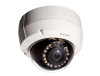
D-Link DCS-6513 User Manual 4 Section 1: Product Overview Product Overview Package Contents DCS‑6513 Full HD WDR Day & Night Outdoor Dome Network Camera Weather Shield Power adapter 37mm Screws for Weather Shield CD-ROM with your reseller. Note: Using a power supply with a different voltage than the one included with User Manual and software Cable Cover Extension Adapter Rubber Plug Security Wrench Quick Installation Guide If any of the above items are missing, please contact your product will cause damage and void the warranty for this product.
D-Link DCS-6513 User Manual 4 Section 1: Product Overview Product Overview Package Contents DCS‑6513 Full HD WDR Day & Night Outdoor Dome Network Camera Weather Shield Power adapter 37mm Screws for Weather Shield CD-ROM with your reseller. Note: Using a power supply with a different voltage than the one included with User Manual and software Cable Cover Extension Adapter Rubber Plug Security Wrench Quick Installation Guide If any of the above items are missing, please contact your product will cause damage and void the warranty for this product.

User Manual
Page 5
...lens that controls the iris with WDR enhancement, users can identify image details in removable IR-cut filter and IR LEDs gives the DCS-6513 the capability to view up to 20M at all times, resulting in a variety of IP67 housing, IR-Cut Filter, IR LEDs ...of field, and image quality. The DCS-6513 also incorporates Power over Ethernet (PoE), allowing it to onboard storage. SDHC Class 6 or above ; The built-in stepping motor maintains the iris opening at an optimal level at night. The DCS-6513 is recommended. • Broadband Internet connection D-Link DCS-6513 User Manual 5
...lens that controls the iris with WDR enhancement, users can identify image details in removable IR-cut filter and IR LEDs gives the DCS-6513 the capability to view up to 20M at all times, resulting in a variety of IP67 housing, IR-Cut Filter, IR LEDs ...of field, and image quality. The DCS-6513 also incorporates Power over Ethernet (PoE), allowing it to onboard storage. SDHC Class 6 or above ; The built-in stepping motor maintains the iris opening at an optimal level at night. The DCS-6513 is recommended. • Broadband Internet connection D-Link DCS-6513 User Manual 5

User Manual
Page 6
... at the camera position and allowing the user to make final adjustments to ensure that it needs from a remote site via Intranet or Internet. D-Link DCS-6513 User Manual 6 PoE (Power over Ethernet) for a separate power installation. Remote Monitoring Utility The D-ViewCam application adds enhanced features and functionality for the Network Camera and allows...
... at the camera position and allowing the user to make final adjustments to ensure that it needs from a remote site via Intranet or Internet. D-Link DCS-6513 User Manual 6 PoE (Power over Ethernet) for a separate power installation. Remote Monitoring Utility The D-ViewCam application adds enhanced features and functionality for the Network Camera and allows...

User Manual
Page 7
... camera's field of view at night 4 Power/Status LED Indicates the camera's current status 5 Protective Casing The camera is also IK-10 certified vandal-resistant. D-Link DCS-6513 User Manual 7
... camera's field of view at night 4 Power/Status LED Indicates the camera's current status 5 Protective Casing The camera is also IK-10 certified vandal-resistant. D-Link DCS-6513 User Manual 7

User Manual
Page 8
D-Link DCS-6513 User Manual 8 Section 1: Product Overview Cable Harness 43 7 6 5 21 1 BNC Connector The BNC connector is recommended for use with handheld monitors to check the Field of View during installation. 2 Power Connector Power connector for the provided 12V DC power adapter. 3 Audio In (A.In) Connects... to a microphone. 4 Audio Out (A.Out) Connects to a speaker. 5 DI/DO Connector I/O connectors for external devices. 12V DC output. 6 Reset Button Press and hold ...
D-Link DCS-6513 User Manual 8 Section 1: Product Overview Cable Harness 43 7 6 5 21 1 BNC Connector The BNC connector is recommended for use with handheld monitors to check the Field of View during installation. 2 Power Connector Power connector for the provided 12V DC power adapter. 3 Audio In (A.In) Connects... to a microphone. 4 Audio Out (A.Out) Connects to a speaker. 5 DI/DO Connector I/O connectors for external devices. 12V DC output. 6 Reset Button Press and hold ...

User Manual
Page 9
Section 1: Product Overview Internal 1 Disassemble the Camera Open the camera enclosure by loosen the 4 screws. Install the Micro SD Card Push the Micro SD card into the slot. 1 Micro SD Card Slot Insert an Micro SD card for local storage of the camera. To eject the Micro SD card, push the Micro SD card into the camera with the gold contacts oriented towards the base of recorded image and video D-Link DCS-6513 User Manual 9 Lift the dome off the base of the camera.
Section 1: Product Overview Internal 1 Disassemble the Camera Open the camera enclosure by loosen the 4 screws. Install the Micro SD Card Push the Micro SD card into the slot. 1 Micro SD Card Slot Insert an Micro SD card for local storage of the camera. To eject the Micro SD card, push the Micro SD card into the camera with the gold contacts oriented towards the base of recorded image and video D-Link DCS-6513 User Manual 9 Lift the dome off the base of the camera.

User Manual
Page 10
... page 9). 2. Use the mounting template to the holes in the ceiling for installation. 5. Attach the surface bracket to the ceiling using the screws provided D-Link DCS-6513 User Manual 10 Thread the cables through the waterproof plugs at the bottom of the base of the camera. Section 2: Assembly and Installation Assembly and Installation Standard...
... page 9). 2. Use the mounting template to the holes in the ceiling for installation. 5. Attach the surface bracket to the ceiling using the screws provided D-Link DCS-6513 User Manual 10 Thread the cables through the waterproof plugs at the bottom of the base of the camera. Section 2: Assembly and Installation Assembly and Installation Standard...

User Manual
Page 11
Push the dome body up over the base of the camera using the three long screws and the provided security screw. Connect the Ethernet cable and the power cable, threading them through the hole in the ceiling. 2. D-Link DCS-6513 User Manual 11 Attach the dome to the base of the camera. 3. Section 2: Assembly and Installation 1.
Push the dome body up over the base of the camera using the three long screws and the provided security screw. Connect the Ethernet cable and the power cable, threading them through the hole in the ceiling. 2. D-Link DCS-6513 User Manual 11 Attach the dome to the base of the camera. 3. Section 2: Assembly and Installation 1.

User Manual
Page 12
Remove the small screw to release the faceplate on the side of the base of the camera D-Link DCS-6513 User Manual 12 Section 2: Assembly and Installation Exposed Cable Installation ƒƒ Height: 23 mm (0.9 inches) ƒƒ Diameter: 183 mm (7.2 inches) ƒƒ Weight: 400 g (0.9 lbs) 1. Disassemble the camera enclosure (see page 9). 2.
Remove the small screw to release the faceplate on the side of the base of the camera D-Link DCS-6513 User Manual 12 Section 2: Assembly and Installation Exposed Cable Installation ƒƒ Height: 23 mm (0.9 inches) ƒƒ Diameter: 183 mm (7.2 inches) ƒƒ Weight: 400 g (0.9 lbs) 1. Disassemble the camera enclosure (see page 9). 2.

User Manual
Page 13
Section 2: Assembly and Installation 1. Attach the dual-holed plate to the corresponding cable connectors. 3. Place the plastic cable cover onto the dual-holed plate and attach it using the screw. Thread the cables through the waterproof plugs on the side of the base of the camera 2. Attach the cables to the base of the camera. D-Link DCS-6513 User Manual 13
Section 2: Assembly and Installation 1. Attach the dual-holed plate to the corresponding cable connectors. 3. Place the plastic cable cover onto the dual-holed plate and attach it using the screw. Thread the cables through the waterproof plugs on the side of the base of the camera 2. Attach the cables to the base of the camera. D-Link DCS-6513 User Manual 13

User Manual
Page 14
... and insert the plastic anchors into these holes. 4. Attach the surface bracket to the ceiling using the three long screws and the provided security screw. D-Link DCS-6513 User Manual 14 Place the dome body onto the base of the camera using the screws provided. 5. Section 2: Assembly and Installation 1.
... and insert the plastic anchors into these holes. 4. Attach the surface bracket to the ceiling using the three long screws and the provided security screw. D-Link DCS-6513 User Manual 14 Place the dome body onto the base of the camera using the screws provided. 5. Section 2: Assembly and Installation 1.

User Manual
Page 15
... it into these holes. 5. Attach the bracket cap to the bottom of the bracket cap to the holes in marking the mounting hole. 3. Mounting Plate D-Link DCS-6513 User Manual Bracket Cap Rubber Seal Pendant Bracket Bracket Cap 15 A template is included to be cut. Locate a suitable position on the ceiling for a 34mm (+2 / -0 mm...
... it into these holes. 5. Attach the bracket cap to the bottom of the bracket cap to the holes in marking the mounting hole. 3. Mounting Plate D-Link DCS-6513 User Manual Bracket Cap Rubber Seal Pendant Bracket Bracket Cap 15 A template is included to be cut. Locate a suitable position on the ceiling for a 34mm (+2 / -0 mm...

User Manual
Page 16
D-Link DCS-6513 User Manual 16 Place the dome body onto the base of the camera. Connect the Ethernet cable and the power cable, then thread them through the pendant bracket. 2. Section 2: Assembly and Installation 1.
D-Link DCS-6513 User Manual 16 Place the dome body onto the base of the camera. Connect the Ethernet cable and the power cable, then thread them through the pendant bracket. 2. Section 2: Assembly and Installation 1.

User Manual
Page 17
Section 2: Assembly and Installation 1. D-Link DCS-6513 User Manual 17 Attach the dome to the base of the camera using the three long screws and the provided security screw.
Section 2: Assembly and Installation 1. D-Link DCS-6513 User Manual 17 Attach the dome to the base of the camera using the three long screws and the provided security screw.

User Manual
Page 18
.... Attach the bracket cap to the bottom of the bracket cap to the bracket cap using the screws provided. 7. Mounting Plate Bent Bracket Bracket Cap D-Link DCS-6513 User Manual Bracket Cap 18 Section 2: Assembly and Installation Bent Mount (Optional) ƒƒ Height: 253 mm (9.96 inches) ƒƒ Diameter: 150 mm (5.9 inches) ƒ...
.... Attach the bracket cap to the bottom of the bracket cap to the bracket cap using the screws provided. 7. Mounting Plate Bent Bracket Bracket Cap D-Link DCS-6513 User Manual Bracket Cap 18 Section 2: Assembly and Installation Bent Mount (Optional) ƒƒ Height: 253 mm (9.96 inches) ƒƒ Diameter: 150 mm (5.9 inches) ƒ...

User Manual
Page 19
Bent Bracket Dome Camera D-Link DCS-6513 User Manual 19 Section 2: Assembly and Installation 1. Place the dome body onto the base of the camera.
Bent Bracket Dome Camera D-Link DCS-6513 User Manual 19 Section 2: Assembly and Installation 1. Place the dome body onto the base of the camera.

User Manual
Page 20
D-Link DCS-6513 User Manual 20 Attach the dome to the base of the camera using the three long screws and the provided security screw. Section 2: Assembly and Installation 1.
D-Link DCS-6513 User Manual 20 Attach the dome to the base of the camera using the three long screws and the provided security screw. Section 2: Assembly and Installation 1.

User Manual
Page 21
... a location where it is recommended that they hold the weather shield in place Install 37mm Screws Weather Shield Remove Existing Screws D-Link DCS-6513 User Manual 21 Step 1: Using a screwdriver, remove the existing two screws which were included in the product package. The weather shield should be exposed to protect your ...
... a location where it is recommended that they hold the weather shield in place Install 37mm Screws Weather Shield Remove Existing Screws D-Link DCS-6513 User Manual 21 Step 1: Using a screwdriver, remove the existing two screws which were included in the product package. The weather shield should be exposed to protect your ...