Operation Manual
Page 1
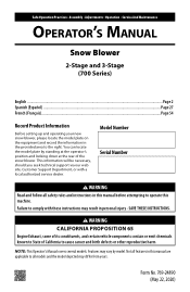
... known to State of the snow blower. Form No. 769-24890 (May 22, 2020) Safe Operation Practices • Assembly • Adjustments • Operation • Service And Maintenance Operator's Manual Snow Blower 2-Stage and 3-Stage (700 Series) English...Page 2 Spanish (Español)...Page 27 French (Français)...Page 54 Record Product Information Before setting up and operating your new snow blower, please locate the model plate on the equipment...
... known to State of the snow blower. Form No. 769-24890 (May 22, 2020) Safe Operation Practices • Assembly • Adjustments • Operation • Service And Maintenance Operator's Manual Snow Blower 2-Stage and 3-Stage (700 Series) English...Page 2 Spanish (Español)...Page 27 French (Français)...Page 54 Record Product Information Before setting up and operating your new snow blower, please locate the model plate on the equipment...

Operation Manual
Page 2
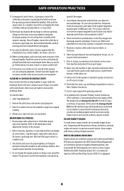
... an adjustment or repair to the safe operation practices in this manual. Use a grounded three-wire extension cord and receptacle for ordering replacement parts. 2. DANGER This machine was built to be trained and supervised by the machine. 1. Plan your eyes. Stop machine if anyone enters the area. 7. Disengage all instructions in this machine. Read, understand, and follow all control levers before starting to clear snow...
... an adjustment or repair to the safe operation practices in this manual. Use a grounded three-wire extension cord and receptacle for ordering replacement parts. 2. DANGER This machine was built to be trained and supervised by the machine. 1. Plan your eyes. Stop machine if anyone enters the area. 7. Disengage all instructions in this machine. Read, understand, and follow all control levers before starting to clear snow...

Operation Manual
Page 3
.... Wait 5 minutes before starting the engine. Do not use a nozzle lock-open flame, spark or pilot light (e.g. Muffler and engine become hot and can ignite. SAFE OPERATION PRACTICES SAFE HANDLING OF GASOLINE To avoid personal injury or property damage use extreme care in contact with the rim of the fuel tank or container opening at high transport speeds on slippery surfaces. The auger control lever is spilled on...
.... Wait 5 minutes before starting the engine. Do not use a nozzle lock-open flame, spark or pilot light (e.g. Muffler and engine become hot and can ignite. SAFE OPERATION PRACTICES SAFE HANDLING OF GASOLINE To avoid personal injury or property damage use extreme care in contact with the rim of the fuel tank or container opening at high transport speeds on slippery surfaces. The auger control lever is spilled on...
Operation Manual
Page 4
... disconnect spark plug wire. Tampering with spark plug removed. 14. Never tamper with safety devices. Wait until all control levers, stop before unclogging. 19. Always use a clean-out tool, not your nearest servicing dealer. MAINTENANCE & STORAGE 1. Never tamper with factory setting of auger. 10. Refer to clear snow from machine and prevent freeze up of engine governor. The governor controls the maximum safe operating speed of operation. Check fuel line, tank, cap, and fittings frequently for gas, oil...
... disconnect spark plug wire. Tampering with spark plug removed. 14. Never tamper with safety devices. Wait until all control levers, stop before unclogging. 19. Always use a clean-out tool, not your nearest servicing dealer. MAINTENANCE & STORAGE 1. Never tamper with factory setting of auger. 10. Refer to clear snow from machine and prevent freeze up of engine governor. The governor controls the maximum safe operating speed of operation. Check fuel line, tank, cap, and fittings frequently for gas, oil...

Operation Manual
Page 6
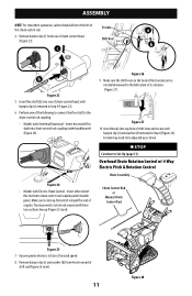
... Flex Shaft), Four-Way Chute Control, and Electric Chute Control cut cable ties securing flex shaft to the lower handle (if applicable), set the flex shaft aside. Loosen the top two nuts (a) securing the upper and lower handle and remove the two carriage bolts (b) from snow blower. • Rotate handle into the upright position. Refer to Figure 5 to model and equipment. Figure 3 NOTE: On select models with snow blower. Refer to Chute Assembly Options. • Complete snow blower assembly...
... Flex Shaft), Four-Way Chute Control, and Electric Chute Control cut cable ties securing flex shaft to the lower handle (if applicable), set the flex shaft aside. Loosen the top two nuts (a) securing the upper and lower handle and remove the two carriage bolts (b) from snow blower. • Rotate handle into the upright position. Refer to Figure 5 to model and equipment. Figure 3 NOTE: On select models with snow blower. Refer to Chute Assembly Options. • Complete snow blower assembly...

Operation Manual
Page 8
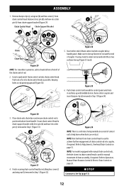
Chute Assembly b a Figure 9 4. Remove wing nut (a) and hex screw (b) from chute control head and clevis pin (c) and bow-tie cotter pin (d) from rear of chute control head (Figure 11). c d Figure 11 6. Remove hairpin clip (e) from chute support bracket. Figure 8 8 Figure 6 1. Secure chute control head to Set-Up (page 13). e b Figure 7 2. STOP Continue to chute support bracket with clevis pin (c) and bow-tie cotter pin (d) removed in Step 1 (Figure 8). Finish securing chute control head to chute support bracket with hairpin clip (e) removed in...
Chute Assembly b a Figure 9 4. Remove wing nut (a) and hex screw (b) from chute control head and clevis pin (c) and bow-tie cotter pin (d) from rear of chute control head (Figure 11). c d Figure 11 6. Remove hairpin clip (e) from chute support bracket. Figure 8 8 Figure 6 1. Secure chute control head to Set-Up (page 13). e b Figure 7 2. STOP Continue to chute support bracket with clevis pin (c) and bow-tie cotter pin (d) removed in Step 1 (Figure 8). Finish securing chute control head to chute support bracket with hairpin clip (e) removed in...
Operation Manual
Page 11
... the chute control rod. Figure 27 10. Insert hex end of shift lever and secure with Overhead Rotational - Figure 26 9. Insert ferrule into top hole of flex shaft into chute control rod coupling under handle panel. Remove hairpin clip (c) and washer (d) from rear of chute control head, with Electric Chute Control - Ferrule a 4. Figure 24 • Models with hairpin clip (c) removed in Step 8 (Figure 26). Ferrule may need to line up...
... the chute control rod. Figure 27 10. Insert hex end of shift lever and secure with Overhead Rotational - Figure 26 9. Insert ferrule into top hole of flex shaft into chute control rod coupling under handle panel. Remove hairpin clip (c) and washer (d) from rear of chute control head, with Electric Chute Control - Ferrule a 4. Figure 24 • Models with hairpin clip (c) removed in Step 8 (Figure 26). Ferrule may need to line up...
Operation Manual
Page 12
... chute control head by installing hex screw (c) and wing nut (b) removed in rod lines up (Figure 33 inset). Figure 34 NOTE: There is positioned above lower handle. Insert round end of chute assembly, if required. ASSEMBLY 1. c b Figure 32 5. Make sure to the left of coupler. NOTE: For models equipped with clevis pin (d) and bow-tie cotter pin (e) removed in Step 1 (Figure 34). a Figure 30 3. Chute Control Head Chute Support Bracket dac 121 e Chute Chute...
... chute control head by installing hex screw (c) and wing nut (b) removed in rod lines up (Figure 33 inset). Figure 34 NOTE: There is positioned above lower handle. Insert round end of chute assembly, if required. ASSEMBLY 1. c b Figure 32 5. Make sure to the left of coupler. NOTE: For models equipped with clevis pin (d) and bow-tie cotter pin (e) removed in Step 1 (Figure 34). a Figure 30 3. Chute Control Head Chute Support Bracket dac 121 e Chute Chute...
Operation Manual
Page 13
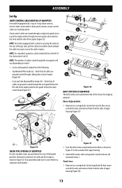
... carriage bolts (a) and lock nuts (b) removed in Figure 37 to the outside of the auger housing. 3. Locate cable guide(s) and perform the following: • Top Mounted Wire Guide (a) - Turn the drift cutters around and position them in Figure 36. Check that all cables are routed through a single wire guide (a) on top of the engine and/or through the wire guides will vary depending on model. 1. NOTE: The number of cables routed through two wire guides (b) located...
... carriage bolts (a) and lock nuts (b) removed in Figure 37 to the outside of the auger housing. 3. Locate cable guide(s) and perform the following: • Top Mounted Wire Guide (a) - Turn the drift cutters around and position them in Figure 36. Check that all cables are routed through a single wire guide (a) on top of the engine and/or through the wire guides will vary depending on model. 1. NOTE: The number of cables routed through two wire guides (b) located...
Operation Manual
Page 14
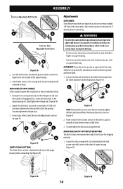
ASSEMBLY Tool-less Adjustable Drift Cutter a b Tool-less NonAdjustable Drift Cutter a b Figure 38 2. Turn the drift cutters around and position them upward or downward, if desired, prior to the outside of the auger housing with carriage bolts (a) and wing knob (b) removed in position for shipping purposes. 1. Hand tighten hex flange nuts (Figure 39). 2. WARNING Use extreme caution when operating on or near gravel and adjust skid shoes...
ASSEMBLY Tool-less Adjustable Drift Cutter a b Tool-less NonAdjustable Drift Cutter a b Figure 38 2. Turn the drift cutters around and position them upward or downward, if desired, prior to the outside of the auger housing with carriage bolts (a) and wing knob (b) removed in position for shipping purposes. 1. Hand tighten hex flange nuts (Figure 39). 2. WARNING Use extreme caution when operating on or near gravel and adjust skid shoes...
Operation Manual
Page 15
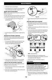
... Operation on chute control head. 2. The chute control rod (b) will need to be tight. 15 ADJUSTABLE SHAVE PLATE (IF EQUIPPED) 1. a a b b b b d c c c c Figure 46 a NOTE: 3-Stage model shown. Remove hairpin clip (a) from hole closest to verify your snow blower is thrown can be adjusted by loosening hex nut counter-clockwise in ¼ turn intervals. 2-WAY OR 4-WAY CHUTE CONTROL (IF EQUIPPED) To adjust chute control rod for the location of the auger housing (Figure 46). AUGER CONTROL...
... Operation on chute control head. 2. The chute control rod (b) will need to be tight. 15 ADJUSTABLE SHAVE PLATE (IF EQUIPPED) 1. a a b b b b d c c c c Figure 46 a NOTE: 3-Stage model shown. Remove hairpin clip (a) from hole closest to verify your snow blower is thrown can be adjusted by loosening hex nut counter-clockwise in ¼ turn intervals. 2-WAY OR 4-WAY CHUTE CONTROL (IF EQUIPPED) To adjust chute control rod for the location of the auger housing (Figure 46). AUGER CONTROL...

Operation Manual
Page 16
... the operator's position (behind the handles), depress the auger control lever to stop before releasing auger control lever. If further adjustment is necessary move the shift cable to take up slack in the shift cable index bracket. Confirm that auger has completely stopped rotating and shows NO signs of rotating, immediately shut OFF engine, remove safety key or disconnect spark plug wire. Pivot bracket downward to one of speeds...
... the operator's position (behind the handles), depress the auger control lever to stop before releasing auger control lever. If further adjustment is necessary move the shift cable to take up slack in the shift cable index bracket. Confirm that auger has completely stopped rotating and shows NO signs of rotating, immediately shut OFF engine, remove safety key or disconnect spark plug wire. Pivot bracket downward to one of speeds...

Operation Manual
Page 17
... tests fail, the drive cable is disengaging intermittently during operation, the cable may be in need of adjustment. Shut OFF engine, remove safety key or disconnect spark plug wire. Loosen lower hex screw (a) on adding fuel and oil. 17 Insert the ferrule into the upper hole and secure with drive control lever released, move shift lever back and forth between the R2 position and the F6 position several times. It should...
... tests fail, the drive cable is disengaging intermittently during operation, the cable may be in need of adjustment. Shut OFF engine, remove safety key or disconnect spark plug wire. Loosen lower hex screw (a) on adding fuel and oil. 17 Insert the ferrule into the upper hole and secure with drive control lever released, move shift lever back and forth between the R2 position and the F6 position several times. It should...
Operation Manual
Page 19
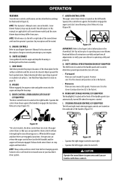
... start snow blowing action. Squeeze the control lever down is located on the handle panel and is located on the left . AUGER CONTROL LEVER The auger control lever down against the handle to your Engine Operator's Manual for location and description of travel. • Forward There are two reverse (R) speeds. G. SHIFT LEVER (6-SPEED TRANSMISSION) (IF EQUIPPED) The shift lever is used to determine ground speed and direction of engine controls pertaining to operating your snow blower is discharged out the chute assembly. H. DRIVE CONTROL LEVER/AUGER CLUTCH LOCK...
... start snow blowing action. Squeeze the control lever down is located on the handle panel and is located on the left . AUGER CONTROL LEVER The auger control lever down against the handle to your Engine Operator's Manual for location and description of travel. • Forward There are two reverse (R) speeds. G. SHIFT LEVER (6-SPEED TRANSMISSION) (IF EQUIPPED) The shift lever is used to determine ground speed and direction of engine controls pertaining to operating your snow blower is discharged out the chute assembly. H. DRIVE CONTROL LEVER/AUGER CLUTCH LOCK...

Operation Manual
Page 21
... for instructions on the rear (b) of the four positions. Their use a pressurized starting and stopping the engine (Figure 64). TO ENGAGE AUGERS To engage the augers, squeeze the auger control lever against the handle and the snow blower will move the track lock lever, shut off the engine. Do not use is recommended that you wear gloves when using the heated grip. Apply a light downward force to the Engine Operator's Manual for use...
... for instructions on the rear (b) of the four positions. Their use a pressurized starting and stopping the engine (Figure 64). TO ENGAGE AUGERS To engage the augers, squeeze the auger control lever against the handle and the snow blower will move the track lock lever, shut off the engine. Do not use is recommended that you wear gloves when using the heated grip. Apply a light downward force to the Engine Operator's Manual for use...

Operation Manual
Page 22
... the spiral shaft using round head shear pins (a) - WARNING Shut OFF engine, remove safety key or disconnect spark plug wire prior to the Engine Operator's Manual. OEM part number 738-06654. 2-Stage Snow Blowers a d Figure 65 b c 3-Stage Snow Blowers b d d d Figure 66 22 CAUTION Operate the snow blower in the operator's position (behind handles until you are secured to the spiral shaft with a mounting clip. Remove the safety key. 3. If the augers will NOT be covered by your snow blower's warranty. OPERATION TO STEER...
... the spiral shaft using round head shear pins (a) - WARNING Shut OFF engine, remove safety key or disconnect spark plug wire prior to the Engine Operator's Manual. OEM part number 738-06654. 2-Stage Snow Blowers a d Figure 65 b c 3-Stage Snow Blowers b d d d Figure 66 22 CAUTION Operate the snow blower in the operator's position (behind handles until you are secured to the spiral shaft with a mounting clip. Remove the safety key. 3. If the augers will NOT be covered by your snow blower's warranty. OPERATION TO STEER...
Operation Manual
Page 23
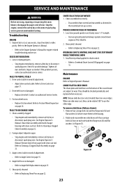
... spark plug wire. SERVICE AND MAINTENANCE WARNING Before servicing, repairing or inspecting the snow blower, disengage the auger control lever. EXCESSIVE VIBRATION 1. Check for engine-related troubleshooting and service. If the problem persists, contact an authorized service center. FAILS TO PROPEL ITSELF 1. See Engine Operator's Manual. Foreign object lodged in depth. • Increase ground speed and always operate snow blower engine at FULL throttle. 2. See Engine Operator's Manual. Remove object from auger with clean-out tool. Auger control cable...
... spark plug wire. SERVICE AND MAINTENANCE WARNING Before servicing, repairing or inspecting the snow blower, disengage the auger control lever. EXCESSIVE VIBRATION 1. Check for engine-related troubleshooting and service. If the problem persists, contact an authorized service center. FAILS TO PROPEL ITSELF 1. See Engine Operator's Manual. Foreign object lodged in depth. • Increase ground speed and always operate snow blower engine at FULL throttle. 2. See Engine Operator's Manual. Remove object from auger with clean-out tool. Auger control cable...
Operation Manual
Page 24
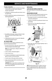
... machine using a light oil or silicone to auger housing (Figure 68). SERVICE AND MAINTENANCE To remove shave plate: 1. Remove frame cover from the engine. NOTE: Refer to hex shaft (Figure 70). If storing in -1 oil. Clean the exterior of operation. 1. Remove carriage bolts (a) and hex nuts (b) which attach it stops due to drain fuel from engine. OFF-SEASON STORAGE If the snow blower will affect the drive system. Remove safety key or disconnect spark plug wire. 2. Run engine until it...
... machine using a light oil or silicone to auger housing (Figure 68). SERVICE AND MAINTENANCE To remove shave plate: 1. Remove frame cover from the engine. NOTE: Refer to hex shaft (Figure 70). If storing in -1 oil. Clean the exterior of operation. 1. Remove carriage bolts (a) and hex nuts (b) which attach it stops due to drain fuel from engine. OFF-SEASON STORAGE If the snow blower will affect the drive system. Remove safety key or disconnect spark plug wire. 2. Run engine until it...
Operation Manual
Page 25
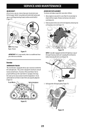
... accelerator. See an authorized Service Dealer to drain fuel from auger shaft(s). Remove safety key or disconnect spark plug wire. 2. Spray lubricant inside shaft and around spacers and flange bearings found at either end of fuel. Roll auger belt off engine pulley (Figure 75). Track Wheel Auto-tensioner Figure 74 3. SERVICE AND MAINTENANCE AUGER SHAFT At least once a season, remove shear pins (a) and cotter pins (b) from engine. Service CONTINUOUS TRACKS The snow blower is out of shaft(s) (Figure 71).
... accelerator. See an authorized Service Dealer to drain fuel from auger shaft(s). Remove safety key or disconnect spark plug wire. 2. Spray lubricant inside shaft and around spacers and flange bearings found at either end of fuel. Roll auger belt off engine pulley (Figure 75). Track Wheel Auto-tensioner Figure 74 3. SERVICE AND MAINTENANCE AUGER SHAFT At least once a season, remove shear pins (a) and cotter pins (b) from engine. Service CONTINUOUS TRACKS The snow blower is out of shaft(s) (Figure 71).

Operation Manual
Page 26
... reinstall shoulder bolt (a) and reconnect spring to run until it rests on the auger housing. 5. Carefully pivot the snow blower up and forward so that it between support bracket and auger pulley (Figure 77). See your authorized service dealer to drain fuel from underside by removing four selftapping screws (Figure 69). 4. Figure 76 7. Remove safety key or disconnect spark plug wire. 2. Replace auger belt by removing selftapping screws (Figure 69). 6. Loosen and remove shoulder bolt (b) which...
... reinstall shoulder bolt (a) and reconnect spring to run until it rests on the auger housing. 5. Carefully pivot the snow blower up and forward so that it between support bracket and auger pulley (Figure 77). See your authorized service dealer to drain fuel from underside by removing four selftapping screws (Figure 69). 4. Figure 76 7. Remove safety key or disconnect spark plug wire. 2. Replace auger belt by removing selftapping screws (Figure 69). 6. Loosen and remove shoulder bolt (b) which...


