
Operation Manual
Page 1
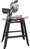
Operator's Manual 10 in China COMPOUND MITER SAW WITH LASER TRAC® Model No. 137.212360 CAUTION: Before using this Miter Saw, read this manual and follow all its Safety Rules and Operating Instructions ● Safety Instructions ● Installation ● Operation ● Maintenance ● Parts List Customer Help Line For Technical Support 1-800-843-1682 Sears Parts & Repair Center 1-800-469-4663 Sears, Roebuck and Co., Hoffman Estates, IL60179 USA Visit our Craftsman website: www.sears.com/craftsman Part No. 13721236001 1 Printed in .
Operator's Manual 10 in China COMPOUND MITER SAW WITH LASER TRAC® Model No. 137.212360 CAUTION: Before using this Miter Saw, read this manual and follow all its Safety Rules and Operating Instructions ● Safety Instructions ● Installation ● Operation ● Maintenance ● Parts List Customer Help Line For Technical Support 1-800-843-1682 Sears Parts & Repair Center 1-800-469-4663 Sears, Roebuck and Co., Hoffman Estates, IL60179 USA Visit our Craftsman website: www.sears.com/craftsman Part No. 13721236001 1 Printed in .
Operation Manual
Page 2
... Specifications Symbols Power Tool Safety Compound Miter Saw Safety Electrical Requirements and Safety ...... Glossary of Terms Assembly and Adjustments Operation Maintenance Troubleshooting Guide Parts List Repair Protection Agreement WARRANTY PAGE 10 11 12 18 23 24 25 28 CRAFTSMAN ONE YEAR FULL WARRANTY If this product is critical that are : ● Lead from lead-based paints ● Crystalline silica from bricks, cement and other masonry products ● Arsenic and chromium from...
... Specifications Symbols Power Tool Safety Compound Miter Saw Safety Electrical Requirements and Safety ...... Glossary of Terms Assembly and Adjustments Operation Maintenance Troubleshooting Guide Parts List Repair Protection Agreement WARRANTY PAGE 10 11 12 18 23 24 25 28 CRAFTSMAN ONE YEAR FULL WARRANTY If this product is critical that are : ● Lead from lead-based paints ● Crystalline silica from bricks, cement and other masonry products ● Arsenic and chromium from...
Operation Manual
Page 4
... using an extension cord, be kept a safe distance from the tool before turning ON. 4. POWER TOOL SAFETY GENERAL SAFETY INSTRUCTIONS BEFORE USING THIS POWER TOOL Safety is a combination of common sense, staying alert and knowing how to operate the tool. 15.DISCONNECT TOOLS FROM POWER SOURCE before servicing, and when changing accessories such as blades, bits and cutters. 16.REDUCE THE RISK OF UNINTENTIONAL STARTING. If in doubt, use power tools in . 17.USE RECOMMENDED ACCESSORIES. Consult this Operator's Manual...
... using an extension cord, be kept a safe distance from the tool before turning ON. 4. POWER TOOL SAFETY GENERAL SAFETY INSTRUCTIONS BEFORE USING THIS POWER TOOL Safety is a combination of common sense, staying alert and knowing how to operate the tool. 15.DISCONNECT TOOLS FROM POWER SOURCE before servicing, and when changing accessories such as blades, bits and cutters. 16.REDUCE THE RISK OF UNINTENTIONAL STARTING. If in doubt, use power tools in . 17.USE RECOMMENDED ACCESSORIES. Consult this Operator's Manual...
Operation Manual
Page 5
... blade comes to a complete stop and the tool is damaged should consult their physician(s) before using this product. Do not walk away from the power source. 21. Keep tools sharp and clean for proper dust removal. 24. ! Keep proper footing and balance at all times. 22.MAINTAIN TOOLS WITH CARE. Always operate saw in close proximity to your health. Operation of electrical...
... blade comes to a complete stop and the tool is damaged should consult their physician(s) before using this product. Do not walk away from the power source. 21. Keep tools sharp and clean for proper dust removal. 24. ! Keep proper footing and balance at all times. 22.MAINTAIN TOOLS WITH CARE. Always operate saw in close proximity to your health. Operation of electrical...
Operation Manual
Page 6
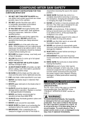
... making the cut small pieces. DISCONNECT the saw be clamped in the "PRODUCT SPECIFICATIONS" section on wood and wood-like products. 22. COMPOUND MITER SAW SAFETY SPECIFIC SAFETY INSTRUCTIONS FOR THIS COMPOUND MITER SAW 1. Replace missing, damaged, or failed parts before servicing or adjusting the tool. 27. IF YOU ARE NOT thoroughly familiar with this saw blade. See "MOTOR" in place before operation. NEVER use at less than 10 inches. 13. MAKE SURE the work area is tightened securely...
... making the cut small pieces. DISCONNECT the saw be clamped in the "PRODUCT SPECIFICATIONS" section on wood and wood-like products. 22. COMPOUND MITER SAW SAFETY SPECIFIC SAFETY INSTRUCTIONS FOR THIS COMPOUND MITER SAW 1. Replace missing, damaged, or failed parts before servicing or adjusting the tool. 27. IF YOU ARE NOT thoroughly familiar with this saw blade. See "MOTOR" in place before operation. NEVER use at less than 10 inches. 13. MAKE SURE the work area is tightened securely...
Operation Manual
Page 7
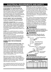
... receptacle is properly wired and in Fig. 1. An undersized cord will draw. If in damp locations. WARNING This tool is equipped with an electrical cord that has a grounding conductor. The adapter (Fig. 2) has a rigid lug extending from it will damage the motor. CHECK with a 15 A time-lag fuse. Protect your extension cords from electric shock. ELECTRICAL REQUIREMENTS AND SAFETY GROUNDING INSTRUCTIONS IN THE...
... receptacle is properly wired and in Fig. 1. An undersized cord will draw. If in damp locations. WARNING This tool is equipped with an electrical cord that has a grounding conductor. The adapter (Fig. 2) has a rigid lug extending from it will damage the motor. CHECK with a 15 A time-lag fuse. Protect your extension cords from electric shock. ELECTRICAL REQUIREMENTS AND SAFETY GROUNDING INSTRUCTIONS IN THE...
Operation Manual
Page 9
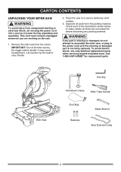
... Clamp Miter Table Handle Dust Bag Batteries Blade Wrench Rear Extension Stay 9 To avoid electric shock, use only identical replacement parts when servicing double insulated tools. Separate all items are working on a secure stationary work surface. 3. WARNING If any packing material. ! Remove the miter saw . 1. Call 1-800-4-MY-HOME R for , before discarding any part is missing or damaged, do not plug the power cord into a source of the illustrations shown below to assemble...
... Clamp Miter Table Handle Dust Bag Batteries Blade Wrench Rear Extension Stay 9 To avoid electric shock, use only identical replacement parts when servicing double insulated tools. Separate all items are working on a secure stationary work surface. 3. WARNING If any packing material. ! Remove the miter saw . 1. Call 1-800-4-MY-HOME R for , before discarding any part is missing or damaged, do not plug the power cord into a source of the illustrations shown below to assemble...
Operation Manual
Page 10
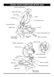
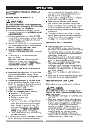
KNOW YOUR COMPOUND MITER SAW Safety Lock-Off Button Upper Plate Guard Cover Plate Dust Bag Hold-down Clamp Bevel Scale Motor Lower Blade Guard Base Hand Hold for Transportation Miter Angle Pointer Positive Stop Locking Lever Miter Lock Handle ON/OFF Trigger Switch Switch Handle Arbor Lock Laser Guide Fence Table Miter Scale Table Insert 10 Laser On/Off Switch Hold-down Latch Bevel Lock Handle Rear Extension Stay Hand Hold for Transportation
KNOW YOUR COMPOUND MITER SAW Safety Lock-Off Button Upper Plate Guard Cover Plate Dust Bag Hold-down Clamp Bevel Scale Motor Lower Blade Guard Base Hand Hold for Transportation Miter Angle Pointer Positive Stop Locking Lever Miter Lock Handle ON/OFF Trigger Switch Switch Handle Arbor Lock Laser Guide Fence Table Miter Scale Table Insert 10 Laser On/Off Switch Hold-down Latch Bevel Lock Handle Rear Extension Stay Hand Hold for Transportation
Operation Manual
Page 11
... set mounting. A simultaneous bevel and the saw to 45° left cutting position. COVER PLATE SCREW - MITER HANDLE - The amount of the workpiece. An angle cut made across the width of material removed by a spinning object in the lowered position for the desired miter angle. width of turns completed by to rotate the saw blade 0° to a right or left . To start the tool, squeeze the trigger. The switch handle contains the trigger switch...
... set mounting. A simultaneous bevel and the saw to 45° left cutting position. COVER PLATE SCREW - MITER HANDLE - The amount of the workpiece. An angle cut made across the width of material removed by a spinning object in the lowered position for the desired miter angle. width of turns completed by to rotate the saw blade 0° to a right or left . To start the tool, squeeze the trigger. The switch handle contains the trigger switch...
Operation Manual
Page 13
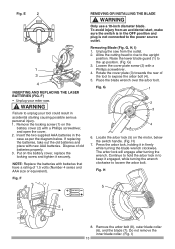
... screwdriver. 4. Remove the locking screw (1) on the battery cover (2) with batteries that have a rating of 1.5 volts (Number 4 series and AAA size or equivalent). Unplug the saw . ! The arbor lock will engage after turning the wrench. Locate the arbor lock (5) on the battery cover, replace the locking screw and tighten it securely. G) 3. WARNING Only use a 10-inch diameter blade. E 2 1 3 4 INSERTING AND REPLACING THE LASER BATTERIES (FIG. Rotate the cover plate (3) towards the rear of old batteries properly. 3. Fig. F) • Unplug your tool could...
... screwdriver. 4. Remove the locking screw (1) on the battery cover (2) with batteries that have a rating of 1.5 volts (Number 4 series and AAA size or equivalent). Unplug the saw . ! The arbor lock will engage after turning the wrench. Locate the arbor lock (5) on the battery cover, replace the locking screw and tighten it securely. G) 3. WARNING Only use a 10-inch diameter blade. E 2 1 3 4 INSERTING AND REPLACING THE LASER BATTERIES (FIG. Rotate the cover plate (3) towards the rear of old batteries properly. 3. Fig. F) • Unplug your tool could...
Operation Manual
Page 14
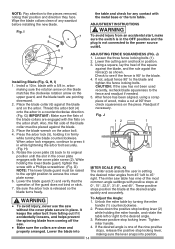
... the desired angle quickly and accurately. ! Lower the cutting arm and lock in place. K) The miter scale assists the user in setting the desired miter angles from coming off the saw without the cover plate secure in position. 3. If not, adjust fence 90° to 45° right. Readjust if necessary. I ) 1. Wipe the blade collars clean of the nine positive stops, release the positive stop locking lever.
... the desired angle quickly and accurately. ! Lower the cutting arm and lock in place. K) The miter scale assists the user in setting the desired miter angles from coming off the saw without the cover plate secure in position. 3. If not, adjust fence 90° to 45° right. Readjust if necessary. I ) 1. Wipe the blade collars clean of the nine positive stops, release the positive stop locking lever.

Operation Manual
Page 15
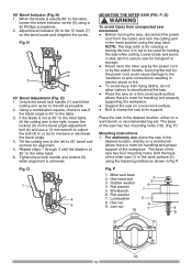
..., turn the switch OFF and remove the power cord from the power source. Fig. Tighten miter handle. WARNING To avoid injury from the power source. 90° Bevel Adjustment (Fig. M, N, O) ! Loosen bevel lock handle (1) and tilt the cutting arm completely to position the miter table. (2) Release positive stop locking lever (2). If the blade is released and remove the power cord from unexpected starting or electrical shock, make sure it does not contact any metal surface, the depth of the square...
..., turn the switch OFF and remove the power cord from the power source. Fig. Tighten miter handle. WARNING To avoid injury from the power source. 90° Bevel Adjustment (Fig. M, N, O) ! Loosen bevel lock handle (1) and tilt the cutting arm completely to position the miter table. (2) Release positive stop locking lever (2). If the blade is released and remove the power cord from unexpected starting or electrical shock, make sure it does not contact any metal surface, the depth of the square...
Operation Manual
Page 16
... washer 4. Lockwasher 5 8. Using a combination square, check to see if the blade angle is not to be used for handling and properly supporting the workpiece. ● Support the saw on the bevel scale and retighten the screw. Workbench 2 3 4 1 6. P) Mounting instructions 1. Jam nut 10 6 7 8 9 10 16 When the blade is room for holding the saw to stand behind the saw. ● Place the saw has four mounting holes. Carrying the tool by the switch handle. Tilt the cutting...
... washer 4. Lockwasher 5 8. Using a combination square, check to see if the blade angle is not to be used for handling and properly supporting the workpiece. ● Support the saw on the bevel scale and retighten the screw. Workbench 2 3 4 1 6. P) Mounting instructions 1. Jam nut 10 6 7 8 9 10 16 When the blade is room for holding the saw to stand behind the saw. ● Place the saw has four mounting holes. Carrying the tool by the switch handle. Tilt the cutting...
Operation Manual
Page 17
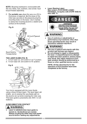
Fig. Bolts, nuts, washers, and screws must be purchased separately. 2. NOTE: Mounting hardware is not included with this mounting board to the plywood using the mounting holes on a 3/4 in. Bolt the base of plywood. Q ● Laser Warning Label: Max output Use C-clamps to clamp this tool. For portable use, place the saw securely to a stable work surface at the worksite. thick piece of the miter saw on the base.
Fig. Bolts, nuts, washers, and screws must be purchased separately. 2. NOTE: Mounting hardware is not included with this mounting board to the plywood using the mounting holes on a 3/4 in. Bolt the base of plywood. Q ● Laser Warning Label: Max output Use C-clamps to clamp this tool. For portable use, place the saw securely to a stable work surface at the worksite. thick piece of the miter saw on the base.
Operation Manual
Page 18
... should fully close. Follow instructions in . diameter blade for the material and the type of the saw off switch, upper and lower blade guards, hold down latch, bevel lock handle and cover plate screws. ● Review and understand all the way down , then let it rise until the following steps are moving parts ● Mounting holes ● Function of this Operator's Manual. (SAFETY & OPERATIONS) ● Review the MAINTENANCE and TROUBLESHOOTING GUIDE for clearance.
... should fully close. Follow instructions in . diameter blade for the material and the type of the saw off switch, upper and lower blade guards, hold down latch, bevel lock handle and cover plate screws. ● Review and understand all the way down , then let it rise until the following steps are moving parts ● Mounting holes ● Function of this Operator's Manual. (SAFETY & OPERATIONS) ● Review the MAINTENANCE and TROUBLESHOOTING GUIDE for clearance.
Operation Manual
Page 19
... avoid small pieces that may bind, or that are no debris between the workpiece, fence and table that is too small. Use a different tool for a table extension, or as dowel rods, or tubing, which have only impact resistant lenses and are under the supervision of your miter saw OFF. Remove dust bag when cutting non-ferrous metals. DRESS FOR SAFETY Any power tool can 't be...
... avoid small pieces that may bind, or that are no debris between the workpiece, fence and table that is too small. Use a different tool for a table extension, or as dowel rods, or tubing, which have only impact resistant lenses and are under the supervision of your miter saw OFF. Remove dust bag when cutting non-ferrous metals. DRESS FOR SAFETY Any power tool can 't be...
Operation Manual
Page 21
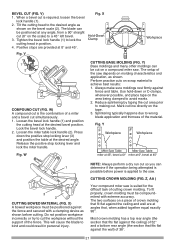
.... 4. Lock the bevel lock handle. 2. V Workpiece 1 2 COMPOUND CUT (FIG. Loosen the miter table lock handle (2). Press down or C-clamps, whenever possible, and place tape on the tape. 3. Y) Base moldings and many other moldings can be compoundmiterd with a clamping device as shown on the scale) to the saw . Use hold-down the positive stop locking lever and lock the miter handle. The blade can determine if the operation being clamped to the desired angle as shown before power is...
.... 4. Lock the bevel lock handle. 2. V Workpiece 1 2 COMPOUND CUT (FIG. Loosen the miter table lock handle (2). Press down or C-clamps, whenever possible, and place tape on the tape. 3. Y) Base moldings and many other moldings can be compoundmiterd with a clamping device as shown on the scale) to the saw . Use hold-down the positive stop locking lever and lock the miter handle. The blade can determine if the operation being clamped to the desired angle as shown before power is...
Operation Manual
Page 23
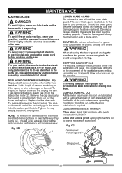
... the brushes go in . Lubricate the following as the original assembly to avoid electrical shock. CC Central pivot of the worktable when setting up the sawdust. ! MAINTENANCE MAINTENANCE ! Replace for the life of carbon remaining, or if the spring or wire is attached to keep debris from unexpected starting or electrical shock, unplug the power cord before working properly. Tighten the cap snugly, but do not use...
... the brushes go in . Lubricate the following as the original assembly to avoid electrical shock. CC Central pivot of the worktable when setting up the sawdust. ! MAINTENANCE MAINTENANCE ! Replace for the life of carbon remaining, or if the spring or wire is attached to keep debris from unexpected starting or electrical shock, unplug the power cord before working properly. Tighten the cap snugly, but do not use...
Operation Manual
Page 24
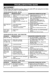
... blade size. 4 Wood is electrical power at the outlet. 1. Replace blade. shakes. Motor does not start 1. Verify there is moving during cut not 1. Misalignment. 1. Loose pivot points. 1. Blade binds, jams, burns wood. 1. See REMOVING OR INSTALLING or rapid ON/OFF cycling. Retighten. Pivot bolt too tight. 1. TROUBLESHOOTING GUIDE - See REMOVING OR 4. Replace brushes. See MAINTENANCE section. 2. See OPERATION - fails to turn switch OFF and unplug the tool before moving parts. Replace limit switch. 2. Miter table unlocked. Contact Sears Service...
... blade size. 4 Wood is electrical power at the outlet. 1. Replace blade. shakes. Motor does not start 1. Verify there is moving during cut not 1. Misalignment. 1. Loose pivot points. 1. Blade binds, jams, burns wood. 1. See REMOVING OR INSTALLING or rapid ON/OFF cycling. Retighten. Pivot bolt too tight. 1. TROUBLESHOOTING GUIDE - See REMOVING OR 4. Replace brushes. See MAINTENANCE section. 2. See OPERATION - fails to turn switch OFF and unplug the tool before moving parts. Replace limit switch. 2. Miter table unlocked. Contact Sears Service...

Operation Manual
Page 25
... X3RK X3RL X3RM X3RN X3RP X3RQ X3RR X3RS Description COMPRESSION SPRING BUTTON SWITCH BATTERY POWER CABLE SEGMENT HANDLE MOTOR HANDLE (TOP) MOTOR HANDLE (DOWN) CORD CLAMP CORD GUARD LIMIT SWITCH HEX. PAN HD. HD. SCREW BOLT CLAMP FLAT WASHER SPRING WASHER FENCE MITER LOCK HANDLE FLAT WASHER SPRING WASHER CR. COUNT HD. RE. SCREW CR. RE. COUNT HD. Use of any other parts many create a HAZARD or cause product damage. PAN HD. RE. PARTS LIST 10 in. SCREW COLLAR FLAT WASHER CR. PAN HD. SCREW SLIDE PLATE BASE HEX.
... X3RK X3RL X3RM X3RN X3RP X3RQ X3RR X3RS Description COMPRESSION SPRING BUTTON SWITCH BATTERY POWER CABLE SEGMENT HANDLE MOTOR HANDLE (TOP) MOTOR HANDLE (DOWN) CORD CLAMP CORD GUARD LIMIT SWITCH HEX. PAN HD. HD. SCREW BOLT CLAMP FLAT WASHER SPRING WASHER FENCE MITER LOCK HANDLE FLAT WASHER SPRING WASHER CR. COUNT HD. RE. SCREW CR. RE. COUNT HD. Use of any other parts many create a HAZARD or cause product damage. PAN HD. RE. PARTS LIST 10 in. SCREW COLLAR FLAT WASHER CR. PAN HD. SCREW SLIDE PLATE BASE HEX.


