
Operation Manual
Page 4
... TOOL IF SWITCH DOES NOT TURN IT ON AND OFF. Always use a clean cloth when clean- Failure to the saw blade. ROW STOCK, A push stick is 10 in this manual or addendums, Use of accessories that are not listed may cause the risk of personal injuw, Instructions for... non-through the blade instead of blade pinching and kickback, always support ]argo panels. • REMOVE ALL FENCES AND AUXILIARY TABLES before connecting to the saw blade. •...
... TOOL IF SWITCH DOES NOT TURN IT ON AND OFF. Always use a clean cloth when clean- Failure to the saw blade. ROW STOCK, A push stick is 10 in this manual or addendums, Use of accessories that are not listed may cause the risk of personal injuw, Instructions for... non-through the blade instead of blade pinching and kickback, always support ]argo panels. • REMOVE ALL FENCES AND AUXILIARY TABLES before connecting to the saw blade. •...

Operation Manual
Page 11
... for a cross cut , with capacitor start and V-belt drive, is provided with the locking handle. BLADE - This saw is housed in the grooves on the saw table surface on the anti-kickback pawls point away from the switch. MITER GAUGE GROOVBS - A sturdy metal... keep the blade guard down over the saw table, these table extension gives the operator additional support when cutting wide workpieoes. The blade is secured with a 36-tooth, 10 in persona] iniury, BLADE GUARD - RIP FENCE - SPREADER - This table extension at 90 ° and 45 _. KNOW YOUR TABLE SAW See Figure ...
... for a cross cut , with capacitor start and V-belt drive, is provided with the locking handle. BLADE - This saw is housed in the grooves on the saw table surface on the anti-kickback pawls point away from the switch. MITER GAUGE GROOVBS - A sturdy metal... keep the blade guard down over the saw table, these table extension gives the operator additional support when cutting wide workpieoes. The blade is secured with a 36-tooth, 10 in persona] iniury, BLADE GUARD - RIP FENCE - SPREADER - This table extension at 90 ° and 45 _. KNOW YOUR TABLE SAW See Figure ...

Operation Manual
Page 14
The following items are included with Spreader and Anti-Kickback Pawls 1 B. Blade Guard with your table saw: It E M P L Fig. 1 A. Indicator (left 1 J. Miter Gauge 1 C. Screw (M4 x 10 ram 2 G. Bevel Handle Assembly 1 14 Spider Leg Stand 1 I. Extension Table (left 1 L, Indicator (right 1 M, Eng Plug (right 1 E. Hex Key 1 Ft Screw (M4 x 25 mm 2 H. Rip Fence 1 D. Blade Wrench 2 O. Dust Bag 1 N, End Plug (left 1 F. Extension Table (right 1 K.
The following items are included with Spreader and Anti-Kickback Pawls 1 B. Blade Guard with your table saw: It E M P L Fig. 1 A. Indicator (left 1 J. Miter Gauge 1 C. Screw (M4 x 10 ram 2 G. Bevel Handle Assembly 1 14 Spider Leg Stand 1 I. Extension Table (left 1 L, Indicator (right 1 M, Eng Plug (right 1 E. Hex Key 1 Ft Screw (M4 x 25 mm 2 H. Rip Fence 1 D. Blade Wrench 2 O. Dust Bag 1 N, End Plug (left 1 F. Extension Table (right 1 K.

Operation Manual
Page 16
...; To roinstaUthe throat plato, align the holes in the saw base to the leg stand_ • Repeat with the holes in the throat plate with the other three locking knobs. Bolts should be bolted securely using a flat blade screwdriver. • Hold the nylon nut securely and turn the ... to overtighten, which can occur during use. HEIGHT/BEVEL ADJUSTINGHANDWHEEL HEXNUT BEVEL HANDLE SCREW WASHER ._;DCAP F_.10 Fig. 9 MOUNTING HOLES The table saw must be of sufficient length to accommodate the saw base with the slots in the top of the leg stand. • InserLthe tab on the locking ...
...; To roinstaUthe throat plato, align the holes in the saw base to the leg stand_ • Repeat with the holes in the throat plate with the other three locking knobs. Bolts should be bolted securely using a flat blade screwdriver. • Hold the nylon nut securely and turn the ... to overtighten, which can occur during use. HEIGHT/BEVEL ADJUSTINGHANDWHEEL HEXNUT BEVEL HANDLE SCREW WASHER ._;DCAP F_.10 Fig. 9 MOUNTING HOLES The table saw must be of sufficient length to accommodate the saw base with the slots in the top of the leg stand. • InserLthe tab on the locking ...

Operation Manual
Page 22
...workpiece just forward of the blade. Miter one end of the workpiece to help control the workpiece by guiding it can resist kickback. _, WARNING: Place the featherboard against the table or fence. hole atthe 8 in., 10 in., and 12 in . Prepare the saw blade area, Adjust the featherboard to... apply resistance to 45" (see page 28 for your saw kerf. Set the rip fence tO allow approxfmately 1/4 in. ...
...workpiece just forward of the blade. Miter one end of the workpiece to help control the workpiece by guiding it can resist kickback. _, WARNING: Place the featherboard against the table or fence. hole atthe 8 in., 10 in., and 12 in . Prepare the saw blade area, Adjust the featherboard to... apply resistance to 45" (see page 28 for your saw kerf. Set the rip fence tO allow approxfmately 1/4 in. ...

Operation Manual
Page 40
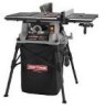
...Center, Contact your table saw requires safety testing to the double insulation system possibly causing eleetricar shock or electrocution. To avoid the possibility of a double insulated product can result in damages to be found on the data plate attached 1o the cabinet. CRAFTSMAN 10 in 2 Screw,...Screw (M6 x 16 mm 1 Block ...1 "Screw (M4 × 25 ram 2 End Plug, Extension Table Rod (left 1 End Plug, Extension Table Rod (right 1 Blade Guard Assembly 1 Screw w/Washer (1/4-20 x 1/2 in . J KEY PART NO. 1 2 3 4 5 6 7 8 9 10 11 12 13 14 15 16 17 18 19 20 21 22 23 24 25 26 27...
...Center, Contact your table saw requires safety testing to the double insulation system possibly causing eleetricar shock or electrocution. To avoid the possibility of a double insulated product can result in damages to be found on the data plate attached 1o the cabinet. CRAFTSMAN 10 in 2 Screw,...Screw (M6 x 16 mm 1 Block ...1 "Screw (M4 × 25 ram 2 End Plug, Extension Table Rod (left 1 End Plug, Extension Table Rod (right 1 Blade Guard Assembly 1 Screw w/Washer (1/4-20 x 1/2 in . J KEY PART NO. 1 2 3 4 5 6 7 8 9 10 11 12 13 14 15 16 17 18 19 20 21 22 23 24 25 26 27...
Operation Manual
Page 42
TABLE SAW - PART NUMBER DESCRIPTION QTY. 0121010919 0134010224 410138743 0121O10906...(MIO) ...1 "C" Ring (56)...1 Special Nut (3/8-16 x 4 2 Bevel indicator ...1 " Screw (M4 x 10 ram 1 Screw (8-16 x 3/4 in 2 Clamping Pad, Power Cord 1 Switch Box ...1 * Carriage Bolt (5/16-18 x 1/2 in 1 Cabinet ...1 Knob ...1 Blade Wrench ...1 Blade Wrench ...1 Knob Ring ...1 power Cord ...1 Switch With Key 1 • Screw (M4 x 20 mm 4 ...42 43 44 45 46 47 48 49 50 51 52 53 54 55 56 57 CRAFTSMAN 10 in .)...4 Knob ...4 Locking Pad ...4 Cabinet Pad ...4 " Screw, Hex. Hd. (M6 x 20 mm 4 Duet ...
TABLE SAW - PART NUMBER DESCRIPTION QTY. 0121010919 0134010224 410138743 0121O10906...(MIO) ...1 "C" Ring (56)...1 Special Nut (3/8-16 x 4 2 Bevel indicator ...1 " Screw (M4 x 10 ram 1 Screw (8-16 x 3/4 in 2 Clamping Pad, Power Cord 1 Switch Box ...1 * Carriage Bolt (5/16-18 x 1/2 in 1 Cabinet ...1 Knob ...1 Blade Wrench ...1 Blade Wrench ...1 Knob Ring ...1 power Cord ...1 Switch With Key 1 • Screw (M4 x 20 mm 4 ...42 43 44 45 46 47 48 49 50 51 52 53 54 55 56 57 CRAFTSMAN 10 in .)...4 Knob ...4 Locking Pad ...4 Cabinet Pad ...4 " Screw, Hex. Hd. (M6 x 20 mm 4 Duet ...


