
Operation Manual
Page 1
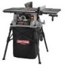
Customer Help Line: 1-800-932-3188 Sears, Roebuck and Co., 3333 Beverly Rd., Hoffman Estates, IL 60179 USA Visit the Craftsman web page: www,sears.com/craftsman 983000-695 8-23-05 Save this product. TABLE SAW Model No. 315.21 8050 _lJ WARNING: To reduce the risk of injury, the user must reed end understand the operator's manual before using this manual for future reference OPERATOR'S MANUAL 10 in.
Customer Help Line: 1-800-932-3188 Sears, Roebuck and Co., 3333 Beverly Rd., Hoffman Estates, IL 60179 USA Visit the Craftsman web page: www,sears.com/craftsman 983000-695 8-23-05 Save this product. TABLE SAW Model No. 315.21 8050 _lJ WARNING: To reduce the risk of injury, the user must reed end understand the operator's manual before using this manual for future reference OPERATOR'S MANUAL 10 in.

Operation Manual
Page 4
... the blade instead of using your hands. Size and shape can pull your saw blade. To minimize risk of blade pinching and kickback, always support ]argo panels. • REMOVE ALL FENCES AND AUXILIARY TABLES before cutting, • NEVER TOUCH BLADE or other parts may cause the... guard down, the antikickback pawls down, and the rivingknife/spreader/ splitter properly aligned to the saw is 10 in ripping or crosscutting. The maximum blade capacity of accessories are included with saw or workplace before connecting to whether the tool iS propedy grounded. • USE ONLY CORRECT ...
... the blade instead of using your hands. Size and shape can pull your saw blade. To minimize risk of blade pinching and kickback, always support ]argo panels. • REMOVE ALL FENCES AND AUXILIARY TABLES before cutting, • NEVER TOUCH BLADE or other parts may cause the... guard down, the antikickback pawls down, and the rivingknife/spreader/ splitter properly aligned to the saw is 10 in ripping or crosscutting. The maximum blade capacity of accessories are included with saw or workplace before connecting to whether the tool iS propedy grounded. • USE ONLY CORRECT ...

Operation Manual
Page 5
...your body in this manual or addendums. Use of accessories that are included with safe operation BEFORE performing any work using the table saw blade guard and dying knife/spreader/ splitter for every operation for overhead guarding. • DO NOT REMOVE JAMMED CUTOFF PIECES until...instructionsalso. _, WARNING" Some dust created by : a) Keeping blade sharp. d) Use a push stickwhen required. b) Use saw . • ALWAYS TURN OFF SAW before it is attached to the saw table for any reason. • MOVE THE RIP FENCE out of these exposures varies, depending on how often you loan someone...
...your body in this manual or addendums. Use of accessories that are included with safe operation BEFORE performing any work using the table saw blade guard and dying knife/spreader/ splitter for every operation for overhead guarding. • DO NOT REMOVE JAMMED CUTOFF PIECES until...instructionsalso. _, WARNING" Some dust created by : a) Keeping blade sharp. d) Use a push stickwhen required. b) Use saw . • ALWAYS TURN OFF SAW before it is attached to the saw table for any reason. • MOVE THE RIP FENCE out of these exposures varies, depending on how often you loan someone...

Operation Manual
Page 9
...{al cut made at any ripping operation. Miter Cut A cutting operation made with both a miter and a bevel ang[s. Riving Knife/Spreader/Splitter (table saws) A metal piece= slightly thinner than the blade, which produces a square-sided notch or trough in a non-through cut orthe slot produced by ... make thinner pieces, Resin A sticky, sap-based substance that the tip of the saw during any angle other than at 90 °, Compound Cut A cross cut . Anti-Kickback Pawls (radial arm and table saws) A device which the operation is being done, Worktable Surface where the warkpieee rests ...
...{al cut made at any ripping operation. Miter Cut A cutting operation made with both a miter and a bevel ang[s. Riving Knife/Spreader/Splitter (table saws) A metal piece= slightly thinner than the blade, which produces a square-sided notch or trough in a non-through cut orthe slot produced by ... make thinner pieces, Resin A sticky, sap-based substance that the tip of the saw during any angle other than at 90 °, Compound Cut A cross cut . Anti-Kickback Pawls (radial arm and table saws) A device which the operation is being done, Worktable Surface where the warkpieee rests ...

Operation Manual
Page 11
...that is inaccessible to children and others not qualified to -read indicator shows the exact angle for a miter cut . This saw table. This lever, placed just under the saw table surface on each side of the rip fence for height adjustments or blade replacement. MITER GAUGE GROOVBS - The powerful industion motor... LOCKING LEVER - Located on the front of the cabinet, use this product, familiarize yourself with a 36-tooth, 10 in which helps keep the blade guard down over the saw blade, which the workpiece is a hazard in . The miter gauge rides in the grooves on the front rail,...
...that is inaccessible to children and others not qualified to -read indicator shows the exact angle for a miter cut . This saw table. This lever, placed just under the saw table surface on each side of the rip fence for height adjustments or blade replacement. MITER GAUGE GROOVBS - The powerful industion motor... LOCKING LEVER - Located on the front of the cabinet, use this product, familiarize yourself with a 36-tooth, 10 in which helps keep the blade guard down over the saw blade, which the workpiece is a hazard in . The miter gauge rides in the grooves on the front rail,...

Operation Manual
Page 14
Dust Bag 1 N, End Plug (left 1 L, Indicator (right 1 M, Eng Plug (right 1 E. Bevel Handle Assembly 1 14 The following items are included with Spreader and Anti-Kickback Pawls 1 B. Blade Guard with your table saw: It E M P L Fig. 1 A. Blade Wrench 2 O. Miter Gauge 1 C. Extension Table (right 1 K. Indicator (left 1 F. Hex Key 1 Ft Screw (M4 x 25 mm 2 H. Screw (M4 x 10 ram 2 G. Rip Fence 1 D. Extension Table (left 1 J. Spider Leg Stand 1 I.
Dust Bag 1 N, End Plug (left 1 L, Indicator (right 1 M, Eng Plug (right 1 E. Bevel Handle Assembly 1 14 The following items are included with Spreader and Anti-Kickback Pawls 1 B. Blade Guard with your table saw: It E M P L Fig. 1 A. Blade Wrench 2 O. Miter Gauge 1 C. Extension Table (right 1 K. Indicator (left 1 F. Hex Key 1 Ft Screw (M4 x 25 mm 2 H. Screw (M4 x 10 ram 2 G. Rip Fence 1 D. Extension Table (left 1 J. Spider Leg Stand 1 I.

Operation Manual
Page 15
... during shipping_ • Do not discard the packing material until you have carefully inspected and satisfactorily operated the tool. • The saw by separating the hook and loop straps. • Place the leg stand on the aide with this tool until assembly iScompTete. Ignoring... these precautions can result in serious personal injury. _k WARNING: To avoid serious personal injury, always make sure the table saw without help when needed. • Inspect the tool carefully to a workbench or an approved leg stand. Failure to heed this warning can...
... during shipping_ • Do not discard the packing material until you have carefully inspected and satisfactorily operated the tool. • The saw by separating the hook and loop straps. • Place the leg stand on the aide with this tool until assembly iScompTete. Ignoring... these precautions can result in serious personal injury. _k WARNING: To avoid serious personal injury, always make sure the table saw without help when needed. • Inspect the tool carefully to a workbench or an approved leg stand. Failure to heed this warning can...

Operation Manual
Page 16
... of the handle. MOUNTING THE TABLE SAW BASE TO THE SPIDER LEG STAND See Figure 9. • Place the table saw base on the back of the workbench, Tighten all four bolts securely. SLOT LOCKING KNOB I I TO INSTALL BEVEL HANDLE ASSEMBLY See Figure 10. • Lift the end ...Lower the bJade by turning the height/bevel adjusting handwheel counterclockwise. HEIGHT/BEVEL ADJUSTINGHANDWHEEL HEXNUT BEVEL HANDLE SCREW WASHER ._;DCAP F_.10 Fig. 9 MOUNTING HOLES The table saw must be bolted securely using a flat blade screwdriver. • Hold the nylon nut securely and turn the screw clockwise ...
... of the handle. MOUNTING THE TABLE SAW BASE TO THE SPIDER LEG STAND See Figure 9. • Place the table saw base on the back of the workbench, Tighten all four bolts securely. SLOT LOCKING KNOB I I TO INSTALL BEVEL HANDLE ASSEMBLY See Figure 10. • Lift the end ...Lower the bJade by turning the height/bevel adjusting handwheel counterclockwise. HEIGHT/BEVEL ADJUSTINGHANDWHEEL HEXNUT BEVEL HANDLE SCREW WASHER ._;DCAP F_.10 Fig. 9 MOUNTING HOLES The table saw must be bolted securely using a flat blade screwdriver. • Hold the nylon nut securely and turn the screw clockwise ...

Operation Manual
Page 17
...14 - 15. Tighten securely. SLOTS To tighten the blade: • Using the smaller blade wrench, place the flat open end on the flats on the table saw. • Lower the blade, • Remove the wing screw and washer from beneath the mount(ng bracket in place ue(ng the washer and wing... nut is half full This will be adjusted for different blade widths. Failure to do so could cause damage to the saw blade, the saw, or the workpiese. • Lower the saw blade pdor to the left. NOTE: Blade alignment with the wing screw ho]e underneath the mounting bracket. • Secure the ...
...14 - 15. Tighten securely. SLOTS To tighten the blade: • Using the smaller blade wrench, place the flat open end on the flats on the table saw. • Lower the blade, • Remove the wing screw and washer from beneath the mount(ng bracket in place ue(ng the washer and wing... nut is half full This will be adjusted for different blade widths. Failure to do so could cause damage to the saw blade, the saw, or the workpiese. • Lower the saw blade pdor to the left. NOTE: Blade alignment with the wing screw ho]e underneath the mounting bracket. • Secure the ...

Operation Manual
Page 20
...; Twistingthe wood while making a cut • Failing to support work properly before beginning a cut . • When making and woodworking NOTE=This table saw • Failing to all local codes and ordinances, Improper connection of the equipment can result in . This helps prevent twisting the wood in the wood... for knots or nails before beginning a cut . Never make cuts with a 90° notch in a specific project. BASIC OPERATION OF THE TABLE SAW The 3-prong plug must be made , CUTI"ING AIDS See Figure 18, Push sticks •are recessed to use in one end and shaping...
...; Twistingthe wood while making a cut • Failing to support work properly before beginning a cut . • When making and woodworking NOTE=This table saw • Failing to all local codes and ordinances, Improper connection of the equipment can result in . This helps prevent twisting the wood in the wood... for knots or nails before beginning a cut . Never make cuts with a 90° notch in a specific project. BASIC OPERATION OF THE TABLE SAW The 3-prong plug must be made , CUTI"ING AIDS See Figure 18, Push sticks •are recessed to use in one end and shaping...

Operation Manual
Page 25
... See Figure 28. relock the front and back locking levers by pushing the lever back towards the saw in place or unlock the extensions for use. • Pullthe front table locking lever toward you to the desired width. This product has two: one on the left and one ... LEVER OUTFEEO SUPPORT Fig. 29 TABLE EXTENSION Fig, 28 25 There are set to give the operator additional support for supporting wider workpieces. The outfeed Support slides to the desired width. Repeat with additional table width for cutting long workpieces. • With the table saw base. TO USE THE OUTFEED ...
... See Figure 28. relock the front and back locking levers by pushing the lever back towards the saw in place or unlock the extensions for use. • Pullthe front table locking lever toward you to the desired width. This product has two: one on the left and one ... LEVER OUTFEEO SUPPORT Fig. 29 TABLE EXTENSION Fig, 28 25 There are set to give the operator additional support for supporting wider workpieces. The outfeed Support slides to the desired width. Repeat with additional table width for cutting long workpieces. • With the table saw base. TO USE THE OUTFEED ...
Operation Manual
Page 33
...8226; Make sure the bevel locking lever is to work properly). • Place the blade washer and the blade nut over the hex nut. The table saw blade to the front of alignment during shipping. However, some of the components might have checked with a flaming square and make practice cuts (n scrap wood... sure it turns freely. • Lower the sew blade and reinstall the throat plate. See To Set the Scale to bow up above the table surface. Holding both wrenches firmly, pull the larger wrench foP,yard to (ts full height by hand to the side of time, readjustment will be...
...8226; Make sure the bevel locking lever is to work properly). • Place the blade washer and the blade nut over the hex nut. The table saw blade to the front of alignment during shipping. However, some of the components might have checked with a flaming square and make practice cuts (n scrap wood... sure it turns freely. • Lower the sew blade and reinstall the throat plate. See To Set the Scale to bow up above the table surface. Holding both wrenches firmly, pull the larger wrench foP,yard to (ts full height by hand to the side of time, readjustment will be...

Operation Manual
Page 39
k CRAFTSMAN 10 in damage to the drive system possibly causing electrical shock or electrocution, Any repairs requiring disassembly of the table saw can resu]t in . TABLE SAW - MODEL NUMBER 315.218050 36 45 co I 34 C B D 2O SEE_OTE"A" _IL WARNING: Lmproperelectrical repair of your tool require safety testing aad should only be performed by a Sears Service Center.
k CRAFTSMAN 10 in damage to the drive system possibly causing electrical shock or electrocution, Any repairs requiring disassembly of the table saw can resu]t in . TABLE SAW - MODEL NUMBER 315.218050 36 45 co I 34 C B D 2O SEE_OTE"A" _IL WARNING: Lmproperelectrical repair of your tool require safety testing aad should only be performed by a Sears Service Center.

Operation Manual
Page 40
... i 1 Glider ...1 " Screw (M6 x 15 ram 3 " Nut (5/8-18NF-2B 1 Flange ...1 Blade ...1 Blade Washer ...1 Spacer ...1 * Washer (1/4 in 2 Screw, Pan Hd. (M4 × 10 ram 2 *Standard Hardwere Item - CRAFTSMAN 10 in all correspondence regarding your table saw requires safety testing to the system, service should be performed by your nearest Sears Repair Center, Contact your nearest Sears Retail...
... i 1 Glider ...1 " Screw (M6 x 15 ram 3 " Nut (5/8-18NF-2B 1 Flange ...1 Blade ...1 Blade Washer ...1 Spacer ...1 * Washer (1/4 in 2 Screw, Pan Hd. (M4 × 10 ram 2 *Standard Hardwere Item - CRAFTSMAN 10 in all correspondence regarding your table saw requires safety testing to the system, service should be performed by your nearest Sears Repair Center, Contact your nearest Sears Retail...

Operation Manual
Page 41
Any repairs requiringdisassembly of the table saw can result in . • CRAFTSMAN 10 in damage to the dnve system possibly causing electrical shock or electrocution. Improper electrical repair of your 1ool require safety testing and should only be performed by a Sears Service Center. 41 TABLE SAW - MODEL NO. 315.218050 21 53 56 22 23 24 8 4 2 46" [J 42 43 51 31 36 \ 54 -37 G ,_L WARNING.
Any repairs requiringdisassembly of the table saw can result in . • CRAFTSMAN 10 in damage to the dnve system possibly causing electrical shock or electrocution. Improper electrical repair of your 1ool require safety testing and should only be performed by a Sears Service Center. 41 TABLE SAW - MODEL NO. 315.218050 21 53 56 22 23 24 8 4 2 46" [J 42 43 51 31 36 \ 54 -37 G ,_L WARNING.
Operation Manual
Page 42
TABLE SAW - May Be Purchased Locally 42 KEY NO. 1 2 3 4 5 6 7 8 9 10 11 12 13 14 15 16 17 ...39 40 41 42 43 44 45 46 47 48 49 50 51 52 53 54 55 56 57 CRAFTSMAN 10 in .)...4 Knob ...4 Locking Pad ...4 Cabinet Pad ...4 " Screw, Hex. MODEL NO. 315.218050 .... Hd. (M6...Hex Wrench (M5 x 75 mm 1 Switch Key ...1 • Screw (M4 x 7 mm 4 Front Guard ...1 * Bolt (M5 x 10 ram 1 "Standard Hardware Item - PART NUMBER DESCRIPTION QTY. 0121010919 0134010224 410138743 0121O10906 0134010316 0121010220 0134011301 41201113 410181001 0121010219 410499O07 0121010316 0121010315 412042002 410134005 ...
TABLE SAW - May Be Purchased Locally 42 KEY NO. 1 2 3 4 5 6 7 8 9 10 11 12 13 14 15 16 17 ...39 40 41 42 43 44 45 46 47 48 49 50 51 52 53 54 55 56 57 CRAFTSMAN 10 in .)...4 Knob ...4 Locking Pad ...4 Cabinet Pad ...4 " Screw, Hex. MODEL NO. 315.218050 .... Hd. (M6...Hex Wrench (M5 x 75 mm 1 Switch Key ...1 • Screw (M4 x 7 mm 4 Front Guard ...1 * Bolt (M5 x 10 ram 1 "Standard Hardware Item - PART NUMBER DESCRIPTION QTY. 0121010919 0134010224 410138743 0121O10906 0134010316 0121010220 0134011301 41201113 410181001 0121010219 410499O07 0121010316 0121010315 412042002 410134005 ...
Operation Manual
Page 43
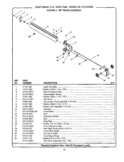
TABLE SAW - MODEL NO, 315,218050 . FIGURE A: RIP FENCE ASSEMBLY 2 6 17 21 16 KEY PART NO. Nylon Nut (M6) ...1 * Washer (M6.5 x 16 x 1.5"1 1 Roar Clamping Plato 1 Compression Spring 1 " Washer (M6,4 x 16 x 1.ST 1 Rip Fence ...1 Hex Screw, Truss Head (M5 x 15 ram 2 "Washer (M6.4 x 16 x 1,5 1 2 * Screw, Pan Head (M4 x 10...16 410431701 17 012101032O 18 410131727 19 0121010233 20 0121010209 21 012101234 22 412011115 A121010901 DESCRIPTION 14 15 QTY. CRAFTSMAN 10 in 2 Front Block Slider ...1 Rip Fence Slider ...2 Front Block Slider ...1 • Washer (D16 &#...
TABLE SAW - MODEL NO, 315,218050 . FIGURE A: RIP FENCE ASSEMBLY 2 6 17 21 16 KEY PART NO. Nylon Nut (M6) ...1 * Washer (M6.5 x 16 x 1.5"1 1 Roar Clamping Plato 1 Compression Spring 1 " Washer (M6,4 x 16 x 1.ST 1 Rip Fence ...1 Hex Screw, Truss Head (M5 x 15 ram 2 "Washer (M6.4 x 16 x 1,5 1 2 * Screw, Pan Head (M4 x 10...16 410431701 17 012101032O 18 410131727 19 0121010233 20 0121010209 21 012101234 22 412011115 A121010901 DESCRIPTION 14 15 QTY. CRAFTSMAN 10 in 2 Front Block Slider ...1 Rip Fence Slider ...2 Front Block Slider ...1 • Washer (D16 &#...
Operation Manual
Page 44
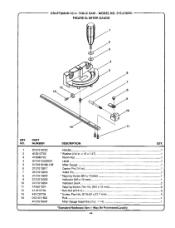
...16 x 1.5 1 NyTonNut ...1 Label ...1 Miter Gauge ...1 Center Pin (1/4 in 1 Index Pin ...1 * Tapping Screw (M4 x 10 ram 1 Indicator (M3 x 12 ram 1 Indicator Deck ...2 Tapping Screw, Pan Hd. (M4 x 12 mm 2 • Hex.... 1-14 1 *Standard Hardware Item - MODEL NO. 315,218050 '" FIGURE B" MITER GAUGE 1 2 3 12 13 14 KEY NO. 1 2 3 4 G 6 7 8 9 10 11 12 13 14 k, PART NUMBER 0121010222 412012705 412080702 9121015330302 0131010109-126 0101010917 0101010918 0121010803 0131O10329 0121010204 410561004 411012704 410132734 0121011802 A121010801 DESCRIPTION QTY. CRAFTSMAN 10 in. TABLE SAW -
...16 x 1.5 1 NyTonNut ...1 Label ...1 Miter Gauge ...1 Center Pin (1/4 in 1 Index Pin ...1 * Tapping Screw (M4 x 10 ram 1 Indicator (M3 x 12 ram 1 Indicator Deck ...2 Tapping Screw, Pan Hd. (M4 x 12 mm 2 • Hex.... 1-14 1 *Standard Hardware Item - MODEL NO. 315,218050 '" FIGURE B" MITER GAUGE 1 2 3 12 13 14 KEY NO. 1 2 3 4 G 6 7 8 9 10 11 12 13 14 k, PART NUMBER 0121010222 412012705 412080702 9121015330302 0131010109-126 0101010917 0101010918 0121010803 0131O10329 0121010204 410561004 411012704 410132734 0121011802 A121010801 DESCRIPTION QTY. CRAFTSMAN 10 in. TABLE SAW -

Operation Manual
Page 45
... Rod ...1 Scale Label ...1 Left Extension Table Assembly (Incl. 1-7 1 *Standard Hardware Item - CRAFTSMAN 10 IN. TABLE SAW - MODEL NO. 315.218050 __ FIGURE C : RIGHT EXTENSION TABLE ASSEMBLY 1 5 4 3 2 KEY NO. 1 2 3 4 5 PART NUMBER 0121010103-126 410171710 0121010909 0121010910 9131015331302 A121013102 DESCRIPTION QTY. May Be Purchased Locally 45 Left Auxiliary Table 1 Front Rod ...1 * Self-Taping Screw (10-24 x 1 in 4 Handle ...1 • Serf...
... Rod ...1 Scale Label ...1 Left Extension Table Assembly (Incl. 1-7 1 *Standard Hardware Item - CRAFTSMAN 10 IN. TABLE SAW - MODEL NO. 315.218050 __ FIGURE C : RIGHT EXTENSION TABLE ASSEMBLY 1 5 4 3 2 KEY NO. 1 2 3 4 5 PART NUMBER 0121010103-126 410171710 0121010909 0121010910 9131015331302 A121013102 DESCRIPTION QTY. May Be Purchased Locally 45 Left Auxiliary Table 1 Front Rod ...1 * Self-Taping Screw (10-24 x 1 in 4 Handle ...1 • Serf...

Operation Manual
Page 46
... NO. 315.218050 ' FIGURE E: OUTFEED SUPPORT ASSEMBLY 1 2 KEY NO. 1 2 3 4 PART NUMBER 410551701 0121010308-58 0121o10911 0121010217 A121013901 =m 3 4 DESCRIPTION QTY. May Be Purchased Locally 46 TABLE SAW - Screw w/Flat Washer. L CRAFTSMAN 10 in 2 Outfeed Support ...1 Rod ...2 PLug...2 Outfeed Support Assembly (Incl. 1-4 1 FIGURE F; Nylon Nut (1/4 in.) ...1 Height/Bevel AdjustingHandwheel 1 Washer (M6.5 x 13 x 1,5"1 1 Bevel Handle ...1 5 0101140203 Screw...
... NO. 315.218050 ' FIGURE E: OUTFEED SUPPORT ASSEMBLY 1 2 KEY NO. 1 2 3 4 PART NUMBER 410551701 0121010308-58 0121o10911 0121010217 A121013901 =m 3 4 DESCRIPTION QTY. May Be Purchased Locally 46 TABLE SAW - Screw w/Flat Washer. L CRAFTSMAN 10 in 2 Outfeed Support ...1 Rod ...2 PLug...2 Outfeed Support Assembly (Incl. 1-4 1 FIGURE F; Nylon Nut (1/4 in.) ...1 Height/Bevel AdjustingHandwheel 1 Washer (M6.5 x 13 x 1,5"1 1 Bevel Handle ...1 5 0101140203 Screw...


