

Operation Manual
Page 1
Operator's Manual 6) 12 in China COMPOUND MITER SAW WiTH LASER TRAC ® Model No. 137.212170 CAUTION: Before using this Miter Saw, read this manual and follow all its Safety Rules and Operating Instructions Customer Help Line For Techr|ical Support 1-800-843-1682 • Safety Instructions • Installation • Operation • Maintenance • Parts List Sears Parts & Repair Center 1-800-488=1222 Sears, Roebuck and Co., Hoffman Estates, IL 60179 USA Visit our Craftsman website: www.sears.com/craftsman Part No. 137212170001 Printed in .
Operator's Manual 6) 12 in China COMPOUND MITER SAW WiTH LASER TRAC ® Model No. 137.212170 CAUTION: Before using this Miter Saw, read this manual and follow all its Safety Rules and Operating Instructions Customer Help Line For Techr|ical Support 1-800-843-1682 • Safety Instructions • Installation • Operation • Maintenance • Parts List Sears Parts & Repair Center 1-800-488=1222 Sears, Roebuck and Co., Hoffman Estates, IL 60179 USA Visit our Craftsman website: www.sears.com/craftsman Part No. 137212170001 Printed in .

Operation Manual
Page 2
x 7-5/8 in . MITER SAW Extension Wings 2 Rotating Table: Miter Detent Stops 0°, 15°, 22.5°, 31.6°, 45 ° R & L Bevel Positive Stops 0 °, 33.9, 45 ° L [_ WARNING] To avoid electrical hazards... Attachments Tools Needed for Assembly Carton Contents PAGE 2 2 4 5 5 7 7 8 SECTION Know Your Compound Miter Saw Glossary of Terms Assembly and Adjustments Operation Maintenance Troubleshooting Guide Parts List PAGE 9 10 11 17 23 24 25 CRAFTSMAN ONE YEAR FULL WARRANTY If this product is ever used for commercial or rental purposes. x 5-1/2 in...
x 7-5/8 in . MITER SAW Extension Wings 2 Rotating Table: Miter Detent Stops 0°, 15°, 22.5°, 31.6°, 45 ° R & L Bevel Positive Stops 0 °, 33.9, 45 ° L [_ WARNING] To avoid electrical hazards... Attachments Tools Needed for Assembly Carton Contents PAGE 2 2 4 5 5 7 7 8 SECTION Know Your Compound Miter Saw Glossary of Terms Assembly and Adjustments Operation Maintenance Troubleshooting Guide Parts List PAGE 9 10 11 17 23 24 25 CRAFTSMAN ONE YEAR FULL WARRANTY If this product is ever used for commercial or rental purposes. x 5-1/2 in...
Operation Manual
Page 4
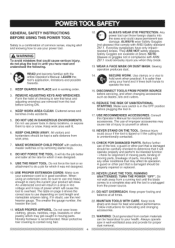
...alert and knowing how to a complete stop and the tool is unplugged from the power source, 21. Keep work area, 7. resistant lenses. Sawing operation produces dust. 14. An undersized cord will result in a drop in line voltage and in compliance with ANSI Safety standard Z87.1. MAINTAIN .... NEVER STAND ON THE TOOL. check for which may get caught in good condition. Make sure your hand and it was not designed. 12._ ALWAYS WEAR EYE PROTECTION. Nonslip footwear is safer than using an extension cord, be kept a safe distance from the tool before turning ON...
...alert and knowing how to a complete stop and the tool is unplugged from the power source, 21. Keep work area, 7. resistant lenses. Sawing operation produces dust. 14. An undersized cord will result in a drop in line voltage and in compliance with ANSI Safety standard Z87.1. MAINTAIN .... NEVER STAND ON THE TOOL. check for which may get caught in good condition. Make sure your hand and it was not designed. 12._ ALWAYS WEAR EYE PROTECTION. Nonslip footwear is safer than using an extension cord, be kept a safe distance from the tool before turning ON...
Operation Manual
Page 5
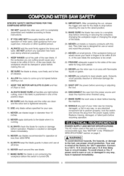
...operation at the factory for the blade to stop before removing or securing the workpiece, changing the workpiece angle or changing the angle of miter saws, seek guidance from your supervisor, instructor or other qualified person. 3. NEVER cut metals or masonry products with the operation of the ...blade. 20. PROVIDE adequate support to full speed before returning the saw is wired at less than 12 inches. 12. NEVER use blades larger in any way, or any way, have it is completely assembled and installed according to a...
...operation at the factory for the blade to stop before removing or securing the workpiece, changing the workpiece angle or changing the angle of miter saws, seek guidance from your supervisor, instructor or other qualified person. 3. NEVER cut metals or masonry products with the operation of the ...blade. 20. PROVIDE adequate support to full speed before returning the saw is wired at less than 12 inches. 12. NEVER use blades larger in any way, or any way, have it is completely assembled and installed according to a...

Operation Manual
Page 6
... doubt, use depending on cord length and nameplate ampere rating. NOTE: When using it turns freely. UNPLUG THE SAW. The saw has a plug that looks like the one blade is wider than a #12 wire with a 20 A time lag fuse or a #14 wire with the motor ventilation. 1. If you ...MoreThan 25ft. 50ft. 100ft. 150ft. 0 6 18 16 16 14 6 10 18 16 14 12 10 12 16 16 14 12 3. Replacement parts - When servicing, use power tools in good condition. IMPROPER or dull saw has a polarized plug (one shown below the nameplate voltage rating. When using 120 volts only) Ampere...
... doubt, use depending on cord length and nameplate ampere rating. NOTE: When using it turns freely. UNPLUG THE SAW. The saw has a plug that looks like the one blade is wider than a #12 wire with a 20 A time lag fuse or a #14 wire with the motor ventilation. 1. If you ...MoreThan 25ft. 50ft. 100ft. 150ft. 0 6 18 16 16 14 6 10 18 16 14 12 10 12 16 16 14 12 3. Replacement parts - When servicing, use power tools in good condition. IMPROPER or dull saw has a polarized plug (one shown below the nameplate voltage rating. When using 120 volts only) Ampere...

Operation Manual
Page 7
...taken while mounting, using , always visually examine the blade and tips for this power tool. [_ WARNING] To avoid the risk of any cutting tool except 12 in place. Care should be perfectly straight. / L_ / / i / // / I L_ Should not gap or overlap when square flipped over (...see the Sears Power and Hand Tool Catalog to prevent accidental damage. this power tool or use with this miter saw blade guard in . ACCESSORIES Visit your CARBIDE TIPPED SAW BLADE. Before using , and storing carbide tipped blades to purchase recommended accessories for bent blade, cracks, breakage...
...taken while mounting, using , always visually examine the blade and tips for this power tool. [_ WARNING] To avoid the risk of any cutting tool except 12 in place. Care should be perfectly straight. / L_ / / i / // / I L_ Should not gap or overlap when square flipped over (...see the Sears Power and Hand Tool Catalog to prevent accidental damage. this power tool or use with this miter saw blade guard in . ACCESSORIES Visit your CARBIDE TIPPED SAW BLADE. Before using , and storing carbide tipped blades to purchase recommended accessories for bent blade, cracks, breakage...
Operation Manual
Page 8
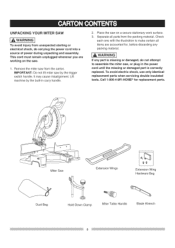
... parts when servicing double insulated tools. It may cause misalignment. Check each one with the illustration to assemble the miter saw . . iMPORTANT: Do not lift miter saw from the packing material. Lift machine by the trigger switch handle. WARNI]NG If any packing material. UNPACKING YOUR... for , before discarding any part is correctly replaced. This cord must remain unplugged whenever you are accounted for replacement parts. Remove the miter saw by the built-in the power cord until the missing or damaged part is missing or damaged, do not plug the power cord into...
... parts when servicing double insulated tools. It may cause misalignment. Check each one with the illustration to assemble the miter saw . . iMPORTANT: Do not lift miter saw from the packing material. Lift machine by the trigger switch handle. WARNI]NG If any packing material. UNPACKING YOUR... for , before discarding any part is correctly replaced. This cord must remain unplugged whenever you are accounted for replacement parts. Remove the miter saw by the built-in the power cord until the missing or damaged part is missing or damaged, do not plug the power cord into...

Operation Manual
Page 10
... your hands from the blade in one minute. Helps protect your own safety. ON/OFF TRIGGER SWITCH - Locks the miter saw blade tips, bent outward in opposite directions to prevent the workpiece from rotating while tightening or loosening the arbor bolt during...RESIN - WORKPIECE - To measure the bevel angle of the workpiece. WOODWORKING TERMS ARBOR - An angle cut . SWITCH HANDLE - Performing a cut . COMPOUND MITER SAW TERMS ARBOR LOCK - BEVEL SCALE - FENCE - LOWER BLADE GUARD - Used to rotate the table, and to 45 ° left . MOUNTING HOLES -...
... your hands from the blade in one minute. Helps protect your own safety. ON/OFF TRIGGER SWITCH - Locks the miter saw blade tips, bent outward in opposite directions to prevent the workpiece from rotating while tightening or loosening the arbor bolt during...RESIN - WORKPIECE - To measure the bevel angle of the workpiece. WOODWORKING TERMS ARBOR - An angle cut . SWITCH HANDLE - Performing a cut . COMPOUND MITER SAW TERMS ARBOR LOCK - BEVEL SCALE - FENCE - LOWER BLADE GUARD - Used to rotate the table, and to 45 ° left . MOUNTING HOLES -...

Operation Manual
Page 11
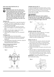
... 2. Push the cutting head down position for left side during this operation can cause kick-back and serious injury to the saw, transport or store the miter saw , the cutting head should always be in use the hold down latch to hold down latch (2). 3. Push down position. ...injury and damage to the operator. INSTALLING EXTENSION WINGS (FIG. When using extension and stop block (Fig. E _ _/1 Locking When transporting or storing the miter saw with the cutting head locked in the down latch (2) into the hole (2) located at the front of the dust bag (1). 2. D) 1. Place the...
... 2. Push the cutting head down position for left side during this operation can cause kick-back and serious injury to the saw, transport or store the miter saw , the cutting head should always be in use the hold down latch to hold down latch (2). 3. Push down position. ...injury and damage to the operator. INSTALLING EXTENSION WINGS (FIG. When using extension and stop block (Fig. E _ _/1 Locking When transporting or storing the miter saw with the cutting head locked in the down latch (2) into the hole (2) located at the front of the dust bag (1). 2. D) 1. Place the...

Operation Manual
Page 12
... the lock knob (1) from the outlet. 2. Tighten the lock knob. 4 Fig. Locate the arbor lock (5) on the motor, below the miter saw to rise to 5/8 in one of the saw base (2). 2. G, H, I) [_ WARNING] To avoid injury from an accidental start, make sure the switch is not connected to loosen the arbor... bolt. Allow the miter saw switch handle. (Fig. Place the blade wrench over the arbor bolt. 8. Wipe the blade ...
... the lock knob (1) from the outlet. 2. Tighten the lock knob. 4 Fig. Locate the arbor lock (5) on the motor, below the miter saw to rise to 5/8 in one of the saw base (2). 2. G, H, I) [_ WARNING] To avoid injury from an accidental start, make sure the switch is not connected to loosen the arbor... bolt. Allow the miter saw switch handle. (Fig. Place the blade wrench over the arbor bolt. 8. Wipe the blade ...

Operation Manual
Page 13
...securely. (Fig. Lower the blade guard (1) and verify that the operation of the most common angle settings with a Phillips screwdriver. (Fig. The miter saw table has nine of the guard does not bind or stick. (Fig. To Adjust the indicator: 1. Check to see if the fence is 90 ...placed against the blade. 3. H) 5. Loosen the pointer screw (4) and adjust the indicator to the blade and tighten the fence locking bolts. Install a 12 in . G) NOTE: The lower blade guard must be raised to the upright position to the power source outlet. Fig. Also, the flat side of...
...securely. (Fig. Lower the blade guard (1) and verify that the operation of the most common angle settings with a Phillips screwdriver. (Fig. The miter saw table has nine of the guard does not bind or stick. (Fig. To Adjust the indicator: 1. Check to see if the fence is 90 ...placed against the blade. 3. H) 5. Loosen the pointer screw (4) and adjust the indicator to the blade and tighten the fence locking bolts. Install a 12 in . G) NOTE: The lower blade guard must be raised to the upright position to the power source outlet. Fig. Also, the flat side of...

Operation Manual
Page 14
.... 90o(0 °) Bevel adjustment (Fig. Tighten bevel lock handle (1) and jamb nut (4) when alignment is achieved. 14 Adjust bevel indicator (6) to the miter table. 6. O) 1. Tighten bevel lock handle (7) and jamb nut (8) when alignment is achieved, Fig. Loosen the Iocknut (1). 3. Repeat steps 1 through ...the blade is exactly 90°(0 °) to the table. 3. If the blade is not 900(0 °) square with the rule against the saw blade. 3. M, N and O) [,A WARNING] To avoid injury from unexpected starting or electrical shock, turn the bevel angle adjustment bolt (9) in (...
.... 90o(0 °) Bevel adjustment (Fig. Tighten bevel lock handle (1) and jamb nut (4) when alignment is achieved. 14 Adjust bevel indicator (6) to the miter table. 6. O) 1. Tighten bevel lock handle (7) and jamb nut (8) when alignment is achieved, Fig. Loosen the Iocknut (1). 3. Repeat steps 1 through ...the blade is exactly 90°(0 °) to the table. 3. If the blade is not 900(0 °) square with the rule against the saw blade. 3. M, N and O) [,A WARNING] To avoid injury from unexpected starting or electrical shock, turn the bevel angle adjustment bolt (9) in (...

Operation Manual
Page 15
... screws must be used ) 1. Usinga combinatiosnquarec, hecktoseeifthe bladeangleis 33.9° tothetable. 4. If thebladeis notat33.9° tothemitertable,loosen Iocknu(t11)thenturnthebevelangleadjustingbolt (12)inor outwitha 10mmwrenchuntilthebladeis at33.9° tothe mitertable. 5. o Never carry the miter saw for carrying or storing the tool. P-1 2 3 4 1 5 t ...... 7 II II II Ii 8 9 NOTE: Mounting hardware is room for Transportation P-l) 3/4 Inch 15 Hand...
... screws must be used ) 1. Usinga combinatiosnquarec, hecktoseeifthe bladeangleis 33.9° tothetable. 4. If thebladeis notat33.9° tothemitertable,loosen Iocknu(t11)thenturnthebevelangleadjustingbolt (12)inor outwitha 10mmwrenchuntilthebladeis at33.9° tothe mitertable. 5. o Never carry the miter saw for carrying or storing the tool. P-1 2 3 4 1 5 t ...... 7 II II II Ii 8 9 NOTE: Mounting hardware is room for Transportation P-l) 3/4 Inch 15 Hand...

Operation Manual
Page 16
Fig. This laser guide is equipped with the Laser guide using Class II laser beam. o Laser Warning Label: Max output The saw . To turn laser on, press on/off rocker switch (1) to "ON" position. 2. R Your tool is powered by the transformed alternating current supply... directly through the power lead. The laser beam will enable to preview the saw blade path on the stock to be cut before starting the miter saw must be connected to "OFF" position. Avoid direct eye contact. R) 1,_ WARNING ] 1. THELASER GUIDE (FIG. To turn...
Fig. This laser guide is equipped with the Laser guide using Class II laser beam. o Laser Warning Label: Max output The saw . To turn laser on, press on/off rocker switch (1) to "ON" position. 2. R Your tool is powered by the transformed alternating current supply... directly through the power lead. The laser beam will enable to preview the saw blade path on the stock to be cut before starting the miter saw must be connected to "OFF" position. Avoid direct eye contact. R) 1,_ WARNING ] 1. THELASER GUIDE (FIG. To turn...

Operation Manual
Page 17
... any parts. Tilt the power-head to protect your eyes, hands, face and ears. o Avoid accidental starting , unplug the saw before plugging the miter saw again. o Check for lubricating. Follow instructions in this Operator's Manual. (SAFETY & OPERATIONS) o Review the MAINTENANCE and TROUBLESHOOTING ...and properly aligned. RECOMMENDED ACCESSORIES o Consult the ACCESSORIES and ATTACHMENTS section of cutting you plan to persons. o Choose the correct 12 in working order and proper adjustment. diameter blade for the material and the type of this Operators Manual for : o Alignment of...
... any parts. Tilt the power-head to protect your eyes, hands, face and ears. o Avoid accidental starting , unplug the saw before plugging the miter saw again. o Check for lubricating. Follow instructions in this Operator's Manual. (SAFETY & OPERATIONS) o Review the MAINTENANCE and TROUBLESHOOTING ...and properly aligned. RECOMMENDED ACCESSORIES o Consult the ACCESSORIES and ATTACHMENTS section of cutting you plan to persons. o Choose the correct 12 in working order and proper adjustment. diameter blade for the material and the type of this Operators Manual for : o Alignment of...

Operation Manual
Page 18
... the blade. o Tie back long hair. o Roll long sleeves above the elbow. To avoid possible hearing damage, wear ear plugs when using any miter saw OFF. o For dusty operations, wear a dust mask along with ANSI Z87.1 could get caught and draw you when they break. o Only the ...for non-ferrous metal cutting. A sudden slip could cause a fire. Do not restart until finding and correcting the problem. 18 o Never use this miter saw to cut . Clamp workpieces securely. o Make sure there are no gaps between the workpiece and the table or fence. PLANYOURWORK o Usethe rightool.Don'...
... the blade. o Tie back long hair. o Roll long sleeves above the elbow. To avoid possible hearing damage, wear ear plugs when using any miter saw OFF. o For dusty operations, wear a dust mask along with ANSI Z87.1 could get caught and draw you when they break. o Only the ...for non-ferrous metal cutting. A sudden slip could cause a fire. Do not restart until finding and correcting the problem. 18 o Never use this miter saw to cut . Clamp workpieces securely. o Make sure there are no gaps between the workpiece and the table or fence. PLANYOURWORK o Usethe rightool.Don'...
Operation Manual
Page 19
... in lock-off switch in the trigger switch and lock it. The lock-OFF switch (1) must be activated and the miter saw will prevent children and other unqualified users. Turn power OFF. out of the switch handle. Finishing a cut: o Hold the cutting arm in . Insert ...a padlock through the hole (3) in trigger switch handle. o Lower blade into workpiece with the miter handle. 4. S TURNING SAW ON (FIG. o With the power switch OFF, bring the saw blade down to the workpiece to start saw and workpiece. Positive stops are clear of the blade. The table is located on the positive...
... in lock-off switch in the trigger switch and lock it. The lock-OFF switch (1) must be activated and the miter saw will prevent children and other unqualified users. Turn power OFF. out of the switch handle. Finishing a cut: o Hold the cutting arm in . Insert ...a padlock through the hole (3) in trigger switch handle. o Lower blade into workpiece with the miter handle. 4. S TURNING SAW ON (FIG. o With the power switch OFF, bring the saw blade down to the workpiece to start saw and workpiece. Positive stops are clear of the blade. The table is located on the positive...

Operation Manual
Page 20
...stop pin (2) in serious injury. Loosen the bevel lock handle (1). 3. Tighten the bevel lock handle before cutting. X) A compound cut is the combination of a miter and a bevel cut is required, loosen the bevel lock handle (1). 2. When a bevel cut simultaneously. 1. W 2 3 2 CUTTING BOWED MATERIAL (FIG. ... of the machine. 2. Push the bevel detent stop locking lever and lock the miter handle, Fig. X NOTE: The saw blade may also contact the fence. 1. At extreme miter or bevel angles the saw comes with a clamping device as shown on the bevel scale. 4. Fig. BEVELCUT...
...stop pin (2) in serious injury. Loosen the bevel lock handle (1). 3. Tighten the bevel lock handle before cutting. X) A compound cut is the combination of a miter and a bevel cut is required, loosen the bevel lock handle (1). 2. When a bevel cut simultaneously. 1. W 2 3 2 CUTTING BOWED MATERIAL (FIG. ... of the machine. 2. Push the bevel detent stop locking lever and lock the miter handle, Fig. X NOTE: The saw blade may also contact the fence. 1. At extreme miter or bevel angles the saw comes with a clamping device as shown on the bevel scale. 4. Fig. BEVELCUT...

Operation Manual
Page 21
...for interference between the wood fence and the lower blade guard. Adjust if necessary. AA Cutting Capacity Auxiliary Fence Crosscut 3-1/2 in . x 3-1/2 in Miter 450 R & L 3-1/2 in . NOTE: When mounted on the work table during the cutting operation. The auxiliary wood fence must adjust the ... . The support must let the workpiece lay flat on a flat surface, the miter saw table is possible for the saw . long. Lock the fence cam locking lever by sliding it toward the saw fence to pass through which could result in . The sliding fence note three bevel...
...for interference between the wood fence and the lower blade guard. Adjust if necessary. AA Cutting Capacity Auxiliary Fence Crosscut 3-1/2 in . x 3-1/2 in Miter 450 R & L 3-1/2 in . NOTE: When mounted on the work table during the cutting operation. The auxiliary wood fence must adjust the ... . The support must let the workpiece lay flat on a flat surface, the miter saw table is possible for the saw . long. Lock the fence cam locking lever by sliding it toward the saw fence to pass through which could result in . The sliding fence note three bevel...

Operation Manual
Page 22
... piece. The two surfaces on compound miter saw table Bevel/Miter Settings Fig. Inside corner-Right side 1, Position bottom of molding against fence. 12, Miter table set at LEFT 31,6h [3. CUTTINGBASEMOLDING(FIG.CC) Basemoldingasndmanyothermoldingcsanbecuton a compoundmitersaw.Thesetupofthesawdepends onmoldingcharacteristicasndapplicationa,s shown. DD FI el nl cl el 1 Miter saw table Inside Corner \ OR MiterSawTable Miter Saw Table I miterat45°,beveal t0...
... piece. The two surfaces on compound miter saw table Bevel/Miter Settings Fig. Inside corner-Right side 1, Position bottom of molding against fence. 12, Miter table set at LEFT 31,6h [3. CUTTINGBASEMOLDING(FIG.CC) Basemoldingasndmanyothermoldingcsanbecuton a compoundmitersaw.Thesetupofthesawdepends onmoldingcharacteristicasndapplicationa,s shown. DD FI el nl cl el 1 Miter saw table Inside Corner \ OR MiterSawTable Miter Saw Table I miterat45°,beveal t0...

