
Operation Manual
Page 1
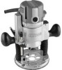
Visit our Craftsman webslta: www.craftsman.com • WARRANTY • SAFETY * UNPACKING * DESCRIPTION • ASSEMBLY • OPERATION = ADJUSTMENTS = MAINTENANCE 9/11/06 4pm Operator's Manual ItenFT- .nN°l 9.5 Amp 13/4 Peak HP Plunge Base Router Model No. 320.17540 DOUBLE tNSULATED Z_ CAUTION Read, understand and follow all Safety Rules and Operating Instructions In this Manual before using this product, Sears, Roebuck and Co_ Hoffman Estates, IL 60179 U°S°A.
Visit our Craftsman webslta: www.craftsman.com • WARRANTY • SAFETY * UNPACKING * DESCRIPTION • ASSEMBLY • OPERATION = ADJUSTMENTS = MAINTENANCE 9/11/06 4pm Operator's Manual ItenFT- .nN°l 9.5 Amp 13/4 Peak HP Plunge Base Router Model No. 320.17540 DOUBLE tNSULATED Z_ CAUTION Read, understand and follow all Safety Rules and Operating Instructions In this Manual before using this product, Sears, Roebuck and Co_ Hoffman Estates, IL 60179 U°S°A.
Operation Manual
Page 2
..., RETURN IT TO THE NEAREST SEARS STORE OR PARTS AND REPAIR CENTER OR OTHER CRAFTSMAN OUTLET INTHE UNITED STATES FOR FREE REPLACEMENT, Thiswarranty dose not Include expendable parts suchas lamps, batteries, bits or blades, If thisCraftsman productIs used for commercial or rental purposes,thiswarranty applies for only g0 days from the date of purchase, Thlswarranty gives you specific legaI dghts, and you...
..., RETURN IT TO THE NEAREST SEARS STORE OR PARTS AND REPAIR CENTER OR OTHER CRAFTSMAN OUTLET INTHE UNITED STATES FOR FREE REPLACEMENT, Thiswarranty dose not Include expendable parts suchas lamps, batteries, bits or blades, If thisCraftsman productIs used for commercial or rental purposes,thiswarranty applies for only g0 days from the date of purchase, Thlswarranty gives you specific legaI dghts, and you...
Operation Manual
Page 3
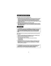
...power tool operation, ALWAYSwear safety goggles or safety glasses with side shletd, available at Sears Stores or other Craftsman Outlets, SYMBOL MEANING /_ SCAFUETTIOYN. The instructionsand warnings they give are no substitutes for use over eyeglasses or standard safety glasses with side shield and a full-face shield when needed. We recommend a Wlde Vision Safety...word"NOTE:" as "DANGER","WARNING" end"CAUTION", BEFORE using this router, Failure to follow the safety precautions to reduce the risk of fire, electric shock and personal Injury, DAMAGE PREVENTION AND INFORMATION MESSAGES ...
...power tool operation, ALWAYSwear safety goggles or safety glasses with side shletd, available at Sears Stores or other Craftsman Outlets, SYMBOL MEANING /_ SCAFUETTIOYN. The instructionsand warnings they give are no substitutes for use over eyeglasses or standard safety glasses with side shield and a full-face shield when needed. We recommend a Wlde Vision Safety...word"NOTE:" as "DANGER","WARNING" end"CAUTION", BEFORE using this router, Failure to follow the safety precautions to reduce the risk of fire, electric shock and personal Injury, DAMAGE PREVENTION AND INFORMATION MESSAGES ...
Operation Manual
Page 4
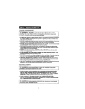
... frees both hands Io operate tool 9. A wrench that there are doing and use common sense when operating a powertool. 3 DO NOT use ° 5. KNOW your work and that ts tstt attached to read and understand etl Instruotlons In this operator'smanual carefully. lL'i_tir4;l--i,I lI r.-i-i;-ti 1-_ Z_ WARNING: BE SURE to a rotatingpart ofthe toolmay result In personal Injury. 7. Keep your power tool. REMOVE adjusting keys or blade wrenches...
... frees both hands Io operate tool 9. A wrench that there are doing and use common sense when operating a powertool. 3 DO NOT use ° 5. KNOW your work and that ts tstt attached to read and understand etl Instruotlons In this operator'smanual carefully. lL'i_tir4;l--i,I lI r.-i-i;-ti 1-_ Z_ WARNING: BE SURE to a rotatingpart ofthe toolmay result In personal Injury. 7. Keep your power tool. REMOVE adjusting keys or blade wrenches...
Operation Manual
Page 5
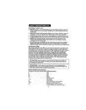
... _. CHECK for the three-wiregrounded power cord and grounded powersupp;y system, Applicable only to Class II (double-Insulated) tools.This router motor Is double Insulated, L_ WARNING: Double Insulation DOES NOT take the place of normal safety 1 precautions when operating this tool Accessories that cannot be suttablefor one tool may become hazardous when used on another tool ELECTRICAL SAFETY InLa_laWltlAnRgNoIrNGre:movDinognthoet ppelrumgiftrofimngtehres otouUtosut,ch...
... _. CHECK for the three-wiregrounded power cord and grounded powersupp;y system, Applicable only to Class II (double-Insulated) tools.This router motor Is double Insulated, L_ WARNING: Double Insulation DOES NOT take the place of normal safety 1 precautions when operating this tool Accessories that cannot be suttablefor one tool may become hazardous when used on another tool ELECTRICAL SAFETY InLa_laWltlAnRgNoIrNGre:movDinognthoet ppelrumgiftrofimngtehres otouUtosut,ch...
Operation Manual
Page 6
... current Direct current No-load speed ,Class11conslrucllonD. cords for an extension cord of at a Sear Service CentareB, E SURE to stay constantlyaware of electric shock If your tool rosy Include the following symbols. For thistool an AWG (American Wire Gauge) size of 50-fL FJdenstoncords 10IPIt. ouble Insulated Revolutionsor Strokesper min_ IndIcatesdanger, warningor caution t! Have damaged loci cords repaired at least 14-gauge is involved 6 Never use power tools...
... current Direct current No-load speed ,Class11conslrucllonD. cords for an extension cord of at a Sear Service CentareB, E SURE to stay constantlyaware of electric shock If your tool rosy Include the following symbols. For thistool an AWG (American Wire Gauge) size of 50-fL FJdenstoncords 10IPIt. ouble Insulated Revolutionsor Strokesper min_ IndIcatesdanger, warningor caution t! Have damaged loci cords repaired at least 14-gauge is involved 6 Never use power tools...
Operation Manual
Page 7
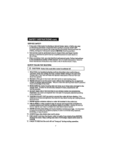
... torque 3_ NEVER attempt to loss of control 9, NEVER hold the workplace rigidly In position, Holdlngthe work by Insulated gripping surfaces (handles) when performing an operation where the cutting tool may creels a dak of elecldc shock or lnlury. ff motor ls not securely clamped fn bess, adjustments will not "hang up or down when damped In the plunge base. DO NOT HAND_HOLDTHE ROUTER...
... torque 3_ NEVER attempt to loss of control 9, NEVER hold the workplace rigidly In position, Holdlngthe work by Insulated gripping surfaces (handles) when performing an operation where the cutting tool may creels a dak of elecldc shock or lnlury. ff motor ls not securely clamped fn bess, adjustments will not "hang up or down when damped In the plunge base. DO NOT HAND_HOLDTHE ROUTER...
Operation Manual
Page 8
... router sub-base, Cutterbits that couldresuit In personatInjury, 24, Aftercompletinge cut,turn motor OFF and let it coma toa completestop BEFORE REMOVING muter from cutting could reeufl In serious personal injury 22,, BE SURE CUTTER BIT Is centered In template guide (sold separately) at Sears stores or otherCraltsman outlets 21. SAFETRYULEFSORROUTERcoSnL 13MAKSEURtEhecuttebritIsnotInoontsct with the workplace before the switch Is turned on this manual...
... router sub-base, Cutterbits that couldresuit In personatInjury, 24, Aftercompletinge cut,turn motor OFF and let it coma toa completestop BEFORE REMOVING muter from cutting could reeufl In serious personal injury 22,, BE SURE CUTTER BIT Is centered In template guide (sold separately) at Sears stores or otherCraltsman outlets 21. SAFETRYULEFSORROUTERcoSnL 13MAKSEURtEhecuttebritIsnotInoontsct with the workplace before the switch Is turned on this manual...
Operation Manual
Page 10
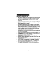
... when you are repfaced_Failure to base • 1/4-in. SAVE THESE INSTRUCTIONS. g. Refer to them frequently and use them to plug In the power cord or operate muter until the broken or missing parts are asssmb!lng parts, maldng adjustments, Installing or removing collate / nuts, cutter bits, cleaning or when It Is not In use thls tool. INSPECT and remove all of thetoo!, a guard or other pert that...
... when you are repfaced_Failure to base • 1/4-in. SAVE THESE INSTRUCTIONS. g. Refer to them frequently and use them to plug In the power cord or operate muter until the broken or missing parts are asssmb!lng parts, maldng adjustments, Installing or removing collate / nuts, cutter bits, cleaning or when It Is not In use thls tool. INSPECT and remove all of thetoo!, a guard or other pert that...
Operation Manual
Page 12
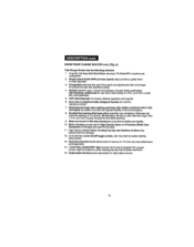
... saw ts p|uggad Intoa power source. Rap|seeable Brushes (soldseparately) fordependable service. 12 I /4-1n, and 1/2-In. Light fs locatedon motorhousing top cap next to provtdathe highestvlslbflltyof bit and workplecoo 8. High.Impact resistantMotor Houelng Top Cap and Handles on motor to powercord IntaL 15. self-releasing collate/nuts for predse set-ups and repetitivecutting, 4 Spindle Leek foreasy l-wrench bit changes.Includes 1/4-1n,end 1/2-1n. maximumcontrol. 7 Base features Isrge base...
... saw ts p|uggad Intoa power source. Rap|seeable Brushes (soldseparately) fordependable service. 12 I /4-1n, and 1/2-In. Light fs locatedon motorhousing top cap next to provtdathe highestvlslbflltyof bit and workplecoo 8. High.Impact resistantMotor Houelng Top Cap and Handles on motor to powercord IntaL 15. self-releasing collate/nuts for predse set-ups and repetitivecutting, 4 Spindle Leek foreasy l-wrench bit changes.Includes 1/4-1n,end 1/2-1n. maximumcontrol. 7 Base features Isrge base...
Operation Manual
Page 14
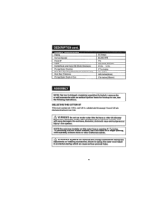
... No4oad Speed Peak HP Inpul Cogets!Nule and Culler BitShank Otamators Plunge Base Dtameler Su b Base Opening (Dtameler forculter b|t use) Sub Base Thickness , ,, PlungeBase Depth of t_14.lnches, To use cutting bits with a larger opening of Cut 9.5 Amps 2'5,000 RPM 1_I_ 12D-voile.6OHz.AC lt4-tn, l12-tn, 6_llE-Inches 1 t/_-|nches o,23-=,_hCes6rnm) 2 Ve-tnches(55ram) NOTE=This tool Is ehlpped completely assembled.To Install or remove bits...
... No4oad Speed Peak HP Inpul Cogets!Nule and Culler BitShank Otamators Plunge Base Dtameler Su b Base Opening (Dtameler forculter b|t use) Sub Base Thickness , ,, PlungeBase Depth of t_14.lnches, To use cutting bits with a larger opening of Cut 9.5 Amps 2'5,000 RPM 1_I_ 12D-voile.6OHz.AC lt4-tn, l12-tn, 6_llE-Inches 1 t/_-|nches o,23-=,_hCes6rnm) 2 Ve-tnches(55ram) NOTE=This tool Is ehlpped completely assembled.To Install or remove bits...
Operation Manual
Page 15
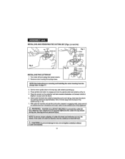
Remove motor housingfrom plunge base. Press spindlelock buttonto engage and lock the splndte shaft and caller!nut,(Fig. 3), 5. Set the molar upsidedown on page 17. 3. Insert cutter bit shank lnlo coflel/nutassembly as far ae It will go, then back the shank out untllthecuttersare approximately 1t8 to tool, do not tighten coltet/nut without a cutter bit Installed° 15 WARNING: TIGHTEN COLLETiNUT SECURELY to prevent the...
Remove motor housingfrom plunge base. Press spindlelock buttonto engage and lock the splndte shaft and caller!nut,(Fig. 3), 5. Set the molar upsidedown on page 17. 3. Insert cutter bit shank lnlo coflel/nutassembly as far ae It will go, then back the shank out untllthecuttersare approximately 1t8 to tool, do not tighten coltet/nut without a cutter bit Installed° 15 WARNING: TIGHTEN COLLETiNUT SECURELY to prevent the...
Operation Manual
Page 16
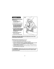
.../nut and router cutter b.ltyou are going to turn motor off and unplug router could result in accidental starting which can cause sedoua personal Injury+ 16 When sharpeningcutterbits, sharpen only the Inside of machine o11to spindle shaft If it te free from power source before Installing. REMOVING THE CUTTER BIT (Figs. 3 end 4 see page 15) 1+ Turnmotor off and unp|ugfrom power source 2 Remove motor from plunge base 3+ Set...
.../nut and router cutter b.ltyou are going to turn motor off and unplug router could result in accidental starting which can cause sedoua personal Injury+ 16 When sharpeningcutterbits, sharpen only the Inside of machine o11to spindle shaft If it te free from power source before Installing. REMOVING THE CUTTER BIT (Figs. 3 end 4 see page 15) 1+ Turnmotor off and unp|ugfrom power source 2 Remove motor from plunge base 3+ Set...
Operation Manual
Page 17
... the motor clamp securely. Leaving bits installed could result in plunge base 5 Set motor upside down . 4. Fig. 5 INSTALLING ROUTER MOTOR tN BASE (Rg, 5) 1, Turnmotoroffandunplug from "keyetrlp slot" (C) in an accident causing sertous personal lnjury_ I NshOoTuEld: Walhweanyms abledncglodsedpthseacdujrueslytm. Wtthmotor houslng'a kayatrlp (C) aligned with the plunge lock lever (B) locked down 4 Lift motor straight up , remove bit, and slore motor and base when not being used Z_ WARNING: ALWAYS remove culler bits lrom colleb'nut when the router ] Is...
... the motor clamp securely. Leaving bits installed could result in plunge base 5 Set motor upside down . 4. Fig. 5 INSTALLING ROUTER MOTOR tN BASE (Rg, 5) 1, Turnmotoroffandunplug from "keyetrlp slot" (C) in an accident causing sertous personal lnjury_ I NshOoTuEld: Walhweanyms abledncglodsedpthseacdujrueslytm. Wtthmotor houslng'a kayatrlp (C) aligned with the plunge lock lever (B) locked down 4 Lift motor straight up , remove bit, and slore motor and base when not being used Z_ WARNING: ALWAYS remove culler bits lrom colleb'nut when the router ] Is...

Operation Manual
Page 19
... plunging the router down unltt the depth-stop rod conlacts the selected step en the depth-stop rod until it contactsthe lowest step on the turret Slide the Clear Plastic Depth-tndlcstor (D) until the red line on , Lock the plunge depth locking lever (F}oThis position is ZERO - DEPTH-STROOPDANDDEPTH-STTOUPRRE(FTigs7,,andS) TheDepth-StRopodandtheDepth-StTouprreatreusedtocontrothl e cuttingdepthasfollows: t Turn motor off and unplug from power source 2 With the cutting bit already installed...
... plunging the router down unltt the depth-stop rod conlacts the selected step en the depth-stop rod until it contactsthe lowest step on the turret Slide the Clear Plastic Depth-tndlcstor (D) until the red line on , Lock the plunge depth locking lever (F}oThis position is ZERO - DEPTH-STROOPDANDDEPTH-STTOUPRRE(FTigs7,,andS) TheDepth-StRopodandtheDepth-StTouprreatreusedtocontrothl e cuttingdepthasfollows: t Turn motor off and unplug from power source 2 With the cutting bit already installed...
Operation Manual
Page 23
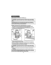
... finishedcut In workplace on the router base with BOTH HANDS at all times. EDGREOUTINOGRINTERNRAOL UTINcoGnt. /_ WARNING: Re=movingcutter bit from w+=rkplee+=, Z_ WARNING: Removing cutter bit free workplace while It I +=+=lmll+=tor your workpl+=ceI+= essential. Learning how the router'+=speed, depth-of *cut , unlockthe=plunge=lock leverand gentiylower the plunge acgon down evenly Into theworkpl+=c+(s=+=+R=g. 13a). INTERNAL ROUTING WITH PLUNGE BASE (Pigs. 13 end 13a...
... finishedcut In workplace on the router base with BOTH HANDS at all times. EDGREOUTINOGRINTERNRAOL UTINcoGnt. /_ WARNING: Re=movingcutter bit from w+=rkplee+=, Z_ WARNING: Removing cutter bit free workplace while It I +=+=lmll+=tor your workpl+=ceI+= essential. Learning how the router'+=speed, depth-of *cut , unlockthe=plunge=lock leverand gentiylower the plunge acgon down evenly Into theworkpl+=c+(s=+=+R=g. 13a). INTERNAL ROUTING WITH PLUNGE BASE (Pigs. 13 end 13a...
Operation Manual
Page 28
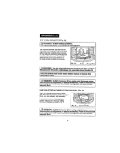
... by a screw To remove the shie}d Imm the plunge base, siroptyremove the screw and take the shield off eZn_d uWnpAlRuNgINroGu:ter cAoLuWldArYeSsutultmtnmacoctoidreonftfaalnsdtaurntipnlgugwhroicuhtercafnrocmaupsoewseerrsioouusrce. II ......... fety guard. Failure to turn motor off of the base Ax WARN!NG: The chip ehtald deflector helps keep dust and chips sway from the operator, It will not stop objects larger than woodchips thrown fmro the bit The chip...
... by a screw To remove the shie}d Imm the plunge base, siroptyremove the screw and take the shield off eZn_d uWnpAlRuNgINroGu:ter cAoLuWldArYeSsutultmtnmacoctoidreonftfaalnsdtaurntipnlgugwhroicuhtercafnrocmaupsoewseerrsioouusrce. II ......... fety guard. Failure to turn motor off of the base Ax WARN!NG: The chip ehtald deflector helps keep dust and chips sway from the operator, It will not stop objects larger than woodchips thrown fmro the bit The chip...

Operation Manual
Page 29
... power tool operations, or when blowing dust, tf operation Is dusty, also wear a dust mask, ROUTINE MAINTENANCE Z_ WARNING: DO NOT st any time let brake fluids, gasoline, petrotaum.basod i I products, penetrating oils, etc. l I/_ WARNING: To ensure safety and reliability, ell repairs should be sarvfced only be used to work has been completed, clean the tool to allowsmooth funclionlng of aHelectricalcables. 4 Keep the motor air...
... power tool operations, or when blowing dust, tf operation Is dusty, also wear a dust mask, ROUTINE MAINTENANCE Z_ WARNING: DO NOT st any time let brake fluids, gasoline, petrotaum.basod i I products, penetrating oils, etc. l I/_ WARNING: To ensure safety and reliability, ell repairs should be sarvfced only be used to work has been completed, clean the tool to allowsmooth funclionlng of aHelectricalcables. 4 Keep the motor air...

Operation Manual
Page 35
Hous(ng Screw Gear Rack "E" Ring Bush S p)nd,le, Lock Nut 3550721000 5630187000 2822039000 Celia( Celia( Nut lntemal Wire Qt 1 ........... 2 1 1 2 1 2 1 2 1 1 2 I 2 2 2 I 1 1 I 1 I 2 I 1 1 1 3 1 1 I 1 I 2 1 I 1 I 1 2 2 35 9.5 Amp/13/4 Peak HP - MODEL NUMBER 320,17540 The Model Number willbe found on the Nameplate, Always mention the Model Number En air correspondence regarding your tool. (tem No, 1 2 3 4 5 8 7 8. 9 10 11 ...........1..2.... 13 14 15 15 17 18 ...........1. 9 20 2I 22 23 24 25 26 27 28 29...
Hous(ng Screw Gear Rack "E" Ring Bush S p)nd,le, Lock Nut 3550721000 5630187000 2822039000 Celia( Celia( Nut lntemal Wire Qt 1 ........... 2 1 1 2 1 2 1 2 1 1 2 I 2 2 2 I 1 1 I 1 I 2 I 1 1 1 3 1 1 I 1 I 2 1 I 1 I 1 2 2 35 9.5 Amp/13/4 Peak HP - MODEL NUMBER 320,17540 The Model Number willbe found on the Nameplate, Always mention the Model Number En air correspondence regarding your tool. (tem No, 1 2 3 4 5 8 7 8. 9 10 11 ...........1..2.... 13 14 15 15 17 18 ...........1. 9 20 2I 22 23 24 25 26 27 28 29...

Operation Manual
Page 36
... 1 48 36500B4000 ,Deplh ,Stop Bar 1 47 35500B3000 .....A..d. tu,sting Pole I 46 5620024000 Screw 2 49 3121635000 50 3121639000 ........5 5670040000 Handle Cover Localed Pin 2 ..........I.. 1 52 3121634000 Depth Indicator 1 53 ..5.,.6,.7.0.0.3.6.000 Pin 1 54 5,63o015oo0Lock Nut 1 55 3420390000 Clamping Lever I 58 3550577000 Mille Look Boll 1 57 3,4_,0,368000 Plunge Frame 1 58 3400189000 Lock Boll 3 59 5620039000 Screw 1 60 3420396000 Plunge Lock Lever 1 61 3660254060 Torsion Spring t 62 5840045000 Bolt 1 ...........6..3 5690120000...
... 1 48 36500B4000 ,Deplh ,Stop Bar 1 47 35500B3000 .....A..d. tu,sting Pole I 46 5620024000 Screw 2 49 3121635000 50 3121639000 ........5 5670040000 Handle Cover Localed Pin 2 ..........I.. 1 52 3121634000 Depth Indicator 1 53 ..5.,.6,.7.0.0.3.6.000 Pin 1 54 5,63o015oo0Lock Nut 1 55 3420390000 Clamping Lever I 58 3550577000 Mille Look Boll 1 57 3,4_,0,368000 Plunge Frame 1 58 3400189000 Lock Boll 3 59 5620039000 Screw 1 60 3420396000 Plunge Lock Lever 1 61 3660254060 Torsion Spring t 62 5840045000 Bolt 1 ...........6..3 5690120000...


