
Maintenance and Service Guide
Page 3
... ...2-26 Removing the Floppy Drive...2-32 Removing the Infrared (I/R) PCA...2-36 Removing the Audio PCA ...2-38 Removing the Heat Sink (with Fan 2-40 Removing the CPU Module ...2-44 Removing the RJ11/1394 Connector Module 2-48 Removing the Motherboard ...2-50 Replacing Components on a Bottom Case 2-59 Repairing the BIOS IC...2-61 Removing...
... ...2-26 Removing the Floppy Drive...2-32 Removing the Infrared (I/R) PCA...2-36 Removing the Audio PCA ...2-38 Removing the Heat Sink (with Fan 2-40 Removing the CPU Module ...2-44 Removing the RJ11/1394 Connector Module 2-48 Removing the Motherboard ...2-50 Replacing Components on a Bottom Case 2-59 Repairing the BIOS IC...2-61 Removing...

Maintenance and Service Guide
Page 4
... 1-3. Front View...1-11 Figure 1-5. Removing an SDRAM Module 2-6 Figure 2-5. Removing the Heat Sink (with Fan 2-43 Figure 2-28. Resetting the Notebook ...1-17 Figure 1-8. Removing the Mini PCI Card 2-7 Figure 2-6. Removing the Mini PCI Card 2-8 Figure 2-7. Removing the Top Case...2-27 Figure 2-...Removing an SDRAM Module 2-5 Figure 2-4. Removing the Keyboard ...2-17 Figure 2-13. Removing the CD/DVD Drive 2-22 Figure 2-17. AMD CPU Module Release 2-47 Figure 2-30. Removing the RJ11/1394 Connector Module 2-49 Figure 2-34. Removing the Motherboard 2-51 Figure 2-35. ...
... 1-3. Front View...1-11 Figure 1-5. Removing an SDRAM Module 2-6 Figure 2-5. Removing the Heat Sink (with Fan 2-43 Figure 2-28. Resetting the Notebook ...1-17 Figure 1-8. Removing the Mini PCI Card 2-7 Figure 2-6. Removing the Mini PCI Card 2-8 Figure 2-7. Removing the Top Case...2-27 Figure 2-...Removing an SDRAM Module 2-5 Figure 2-4. Removing the Keyboard ...2-17 Figure 2-13. Removing the CD/DVD Drive 2-22 Figure 2-17. AMD CPU Module Release 2-47 Figure 2-30. Removing the RJ11/1394 Connector Module 2-49 Figure 2-34. Removing the Motherboard 2-51 Figure 2-35. ...
Maintenance and Service Guide
Page 29
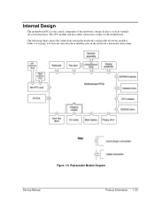
The following figure shows the connections among the notebook's replaceable electronic modules. Table 1-8 on page 1-25 lists the roles that these modules play in virtually all system functions. Internal Design The motherboard PCA is the central component of the notebook's design. Replaceable Module Diagram Service Manual Product Information 1-23 It plays a role in the notebook's functional subsystems. Figure 1-8. The CPU module and most other subsystems connect to the motherboard.
The following figure shows the connections among the notebook's replaceable electronic modules. Table 1-8 on page 1-25 lists the roles that these modules play in virtually all system functions. Internal Design The motherboard PCA is the central component of the notebook's design. Replaceable Module Diagram Service Manual Product Information 1-23 It plays a role in the notebook's functional subsystems. Figure 1-8. The CPU module and most other subsystems connect to the motherboard.
Maintenance and Service Guide
Page 30
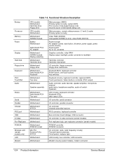
... Serial Parallel Infrared PS/2 port USB S-Video Port Replicator PCMCIA Wireless LAN (certain models only) LAN Modem Table 1-8. Functional Structure Description CPU module Motherboard Hard disk drive Floppy drive CPU module Motherboard Motherboard SDRAM module Battery Motherboard Switchboard PCA AC adapter Motherboard SDRAM module Display assembly Motherboard Hard disk drive Motherboard Floppy...
... Serial Parallel Infrared PS/2 port USB S-Video Port Replicator PCMCIA Wireless LAN (certain models only) LAN Modem Table 1-8. Functional Structure Description CPU module Motherboard Hard disk drive Floppy drive CPU module Motherboard Motherboard SDRAM module Battery Motherboard Switchboard PCA AC adapter Motherboard SDRAM module Display assembly Motherboard Hard disk drive Motherboard Floppy...
Maintenance and Service Guide
Page 31
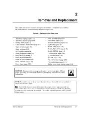
..., speaker (page 2-15) • Battery, main (page 2-4) • Card, wireless LAN Mini PCI (page 2-7) Case, bottom (page 2-59) Case, top (page 2-26) CPU module (page 2-44) • Cover, keyboard (page 2-16) • Door, Mini PCI (page 2-7) • Door, SDRAM (page 2-5) Doors, PCMCIA (page 2-60) Drive...CAUTION: Always provide proper grounding when performing repairs. NOTE: Reassembly steps are user-replaceable. Installing a wrong-size screw can damage the notebook and its components. The items marked by • in the following table are the reverse of screws before you how to show ...
..., speaker (page 2-15) • Battery, main (page 2-4) • Card, wireless LAN Mini PCI (page 2-7) Case, bottom (page 2-59) Case, top (page 2-26) CPU module (page 2-44) • Cover, keyboard (page 2-16) • Door, Mini PCI (page 2-7) • Door, SDRAM (page 2-5) Doors, PCMCIA (page 2-60) Drive...CAUTION: Always provide proper grounding when performing repairs. NOTE: Reassembly steps are user-replaceable. Installing a wrong-size screw can damage the notebook and its components. The items marked by • in the following table are the reverse of screws before you how to show ...

Maintenance and Service Guide
Page 71
... (page 2-26) • Heat sink (page 2-40) Service Manual Removal and Replacement 2-41 Removing the CPU Module (Authorized Service Providers Only) Required Equipment Small flat-blade (3mm) screwdriver NOTE: This section applies only to HP Pavilion 4x00, HP Compaq nx9005 and nx9000, Compaq Evo Notebook N1050v and N1010v, and Compaq Presario 2100 and 1100 models.
... (page 2-26) • Heat sink (page 2-40) Service Manual Removal and Replacement 2-41 Removing the CPU Module (Authorized Service Providers Only) Required Equipment Small flat-blade (3mm) screwdriver NOTE: This section applies only to HP Pavilion 4x00, HP Compaq nx9005 and nx9000, Compaq Evo Notebook N1050v and N1010v, and Compaq Presario 2100 and 1100 models.

Maintenance and Service Guide
Page 72
...way). To install, carefullu insert the CPU module into the motherboard (the CPU module is keyed for installation and can be installed. Intel CPU Module Removal HP Pavilion 4x00, HP Compaq nx9005 and nx9000, Compaq Evo Notebook N1050v and N1010v, and Compaq Presario 2100 and 1100 Models CAUTION:... Each time you install a new CPU module, you should here a light snap) to step 4. ...
...way). To install, carefullu insert the CPU module into the motherboard (the CPU module is keyed for installation and can be installed. Intel CPU Module Removal HP Pavilion 4x00, HP Compaq nx9005 and nx9000, Compaq Evo Notebook N1050v and N1010v, and Compaq Presario 2100 and 1100 Models CAUTION:... Each time you install a new CPU module, you should here a light snap) to step 4. ...

Maintenance and Service Guide
Page 73
... in the directon shown by the arrow until a Select is felt or heard. AMD CPU Module Removal HP Pavilion 4x00, HP Compaq nx9005 and nx9000, Compaq Evo Notebook N1050v and N1010v, and Compaq Presario 2100 and 1100 Models Service Manual Removal and Replacement 2-43 Place a flat-blade ...screwdriver (with the following substeps: a. Carefully grasp the CPU module bythe edges and lift the module...
... in the directon shown by the arrow until a Select is felt or heard. AMD CPU Module Removal HP Pavilion 4x00, HP Compaq nx9005 and nx9000, Compaq Evo Notebook N1050v and N1010v, and Compaq Presario 2100 and 1100 Models Service Manual Removal and Replacement 2-43 Place a flat-blade ...screwdriver (with the following substeps: a. Carefully grasp the CPU module bythe edges and lift the module...

Maintenance and Service Guide
Page 74
...the illustration below to secure the CPU module into the position shown in Figure 2-31 and move as indicated by the arrow in one way). AMD CPU Module Installation HP Pavilion 4x00, HP Compaq nx9005 and nx9000, Compaq Evo Notebook N1050v and N1010v, and Compaq Presario 2100 and 1100 Models CAUTION:... Each time you install a new CPU module, you must also replace the heat sink's thermal pad...
...the illustration below to secure the CPU module into the position shown in Figure 2-31 and move as indicated by the arrow in one way). AMD CPU Module Installation HP Pavilion 4x00, HP Compaq nx9005 and nx9000, Compaq Evo Notebook N1050v and N1010v, and Compaq Presario 2100 and 1100 Models CAUTION:... Each time you install a new CPU module, you must also replace the heat sink's thermal pad...

Maintenance and Service Guide
Page 76
... optimum heat transfer. Carefully lift the CPU module off of its socket on the heat sink, as described in the Caution above. 2-46 Removal and Replacement Service Manual Removing the CPU Module HP Pavilion ze5x00, HP nx9010 and HPnx9008, and Compaq Presario 2500 Models CAUTION: Each time ...you install a new CPU module, you must also replace the heat sink's thermal pad to carefully remove ...
... optimum heat transfer. Carefully lift the CPU module off of its socket on the heat sink, as described in the Caution above. 2-46 Removal and Replacement Service Manual Removing the CPU Module HP Pavilion ze5x00, HP nx9010 and HPnx9008, and Compaq Presario 2500 Models CAUTION: Each time ...you install a new CPU module, you must also replace the heat sink's thermal pad to carefully remove ...

Maintenance and Service Guide
Page 85
.... Wireless Models Only • Before installing the motherboard, make sure the round coaxial cables from the antenna PCAs are replacing the CPU module, you must use the Service Utilities floppy disk to display the boot menu, and then boot from the Partnership Web site ...AC adapter. 3. Service Manual Removal and Replacement 2-55 Insert the Service Utilities floppy disk in the package's Readme file. 2. Download the notebook Series service package from the floppy drive. 6. Reassembly Notes NOTE: After replacing the display assembly or motherboard, you must also replace the ...
.... Wireless Models Only • Before installing the motherboard, make sure the round coaxial cables from the antenna PCAs are replacing the CPU module, you must use the Service Utilities floppy disk to display the boot menu, and then boot from the Partnership Web site ...AC adapter. 3. Service Manual Removal and Replacement 2-55 Insert the Service Utilities floppy disk in the package's Readme file. 2. Download the notebook Series service package from the floppy drive. 6. Reassembly Notes NOTE: After replacing the display assembly or motherboard, you must also replace the ...

Maintenance and Service Guide
Page 86
... the BIOS IC A new BIOS IC contains only enough basic programming to enable the notebook to the next step. 5. Enter the serial number from the old motherboard, and then install onto the new motherboard: • CPU module • Wireless LAN Mini PCI card (if present) • SDRAM modules ... support center to store the system data and display information in an AC adapter. 2. Remove the following components from the bottom of the notebook-you did not store system data, type M for the automatic update. Plug in the EEPROM on the motherboard. Select the Serial Number...
... the BIOS IC A new BIOS IC contains only enough basic programming to enable the notebook to the next step. 5. Enter the serial number from the old motherboard, and then install onto the new motherboard: • CPU module • Wireless LAN Mini PCI card (if present) • SDRAM modules ... support center to store the system data and display information in an AC adapter. 2. Remove the following components from the bottom of the notebook-you did not store system data, type M for the automatic update. Plug in the EEPROM on the motherboard. Select the Serial Number...

Maintenance and Service Guide
Page 91
... listed in the Control Panel. See page 2-3 Service Manual Removal and Replacement 2-61 Removing Components Component Battery, CMOS Case, bottom Case, top CD/DVD drive CPU module Display assembly Doors, PCMCIA Floppy drive Removal Procedure Keyboard cover(page 2-13) Speaker (page 2-15) Keyboard (page 2-16) Switchboard PCA(page 2-19) CD/DVD...
... listed in the Control Panel. See page 2-3 Service Manual Removal and Replacement 2-61 Removing Components Component Battery, CMOS Case, bottom Case, top CD/DVD drive CPU module Display assembly Doors, PCMCIA Floppy drive Removal Procedure Keyboard cover(page 2-13) Speaker (page 2-15) Keyboard (page 2-16) Switchboard PCA(page 2-19) CD/DVD...

Maintenance and Service Guide
Page 100
..., and replace the top case, replace the motherboard. If the power status light does not turn notebook off , try again. If monitor shows successful boot, replace display assembly. Troubleshooting Suggestions Symptom Call...AC adapter, remove the battery and any other SDRAM module and try again. Reinsert any PC cards, press the reset button to turn on but does not boot Make sure at ...on . If monitor is installed. If OS starts from hard disk or floppy drive, replace CPU module, replace motherboard. If you cannot isolate the cause of a problem, determine which replaceable ...
..., and replace the top case, replace the motherboard. If the power status light does not turn notebook off , try again. If monitor shows successful boot, replace display assembly. Troubleshooting Suggestions Symptom Call...AC adapter, remove the battery and any other SDRAM module and try again. Reinsert any PC cards, press the reset button to turn on but does not boot Make sure at ...on . If monitor is installed. If OS starts from hard disk or floppy drive, replace CPU module, replace motherboard. If you cannot isolate the cause of a problem, determine which replaceable ...

Maintenance and Service Guide
Page 103
... power supply. Press Fn+F5 several times. Make sure CPU module is loading and checking hardware and network connections. Blinking cursor appears while system is installed properly, replace CPU module. If notebook is installed. Try external monitor. Service Manual Troubleshooting and ...to resume if network card is busy, it normally finishes current operation before entering (or allowing notebook to Never. Display cable connection SDRAM modules CPU module Display assembly Motherboard White display Adjust display brightness. Check display cable connections, replace display ...
... power supply. Press Fn+F5 several times. Make sure CPU module is loading and checking hardware and network connections. Blinking cursor appears while system is installed properly, replace CPU module. If notebook is installed. Try external monitor. Service Manual Troubleshooting and ...to resume if network card is busy, it normally finishes current operation before entering (or allowing notebook to Never. Display cable connection SDRAM modules CPU module Display assembly Motherboard White display Adjust display brightness. Check display cable connections, replace display ...

Maintenance and Service Guide
Page 111
...response time). Delete temporary and unneeded files. CMOS battery Motherboard Heat sink CPU module Motherboard Check notebook's power supply. Check heat sink for damage or proper fan operation. Games and other programs that drive CPU usage toward 100% can flow freely around and underneath it can take ...several seconds to charge CMOS battery. Press ctrl+alt+del to modify hard disk power settings. If notebook's hard drive frequently runs (as virus scanning...
...response time). Delete temporary and unneeded files. CMOS battery Motherboard Heat sink CPU module Motherboard Check notebook's power supply. Check heat sink for damage or proper fan operation. Games and other programs that drive CPU usage toward 100% can flow freely around and underneath it can take ...several seconds to charge CMOS battery. Press ctrl+alt+del to modify hard disk power settings. If notebook's hard drive frequently runs (as virus scanning...

Maintenance and Service Guide
Page 114
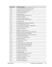
...a sequence of initialization routines and diagnostic tests called POST (Power-On Self-Test). The BIOS will not boot the notebook's operating system if the system memory, CPU, DMA, or interrupt controller fails the POST diagnostic tests. POST indicates progress by performing a "clean" boot, as...SDRAM modules, port replicator, PC cards, printer, external monitor, pointing device, and keyboard. 2. The beep code indicates the POST routine in the notebook-some messages are for option ROMs Verify Real Mode Disable Non-Maskable Interrupt (NMI) Get CPU type Initialize system hardware Disable...
...a sequence of initialization routines and diagnostic tests called POST (Power-On Self-Test). The BIOS will not boot the notebook's operating system if the system memory, CPU, DMA, or interrupt controller fails the POST diagnostic tests. POST indicates progress by performing a "clean" boot, as...SDRAM modules, port replicator, PC cards, printer, external monitor, pointing device, and keyboard. 2. The beep code indicates the POST routine in the notebook-some messages are for option ROMs Verify Real Mode Disable Non-Maskable Interrupt (NMI) Get CPU type Initialize system hardware Disable...
Maintenance and Service Guide
Page 115
...start shut down Shadow system BIOS ROM Auto size cache Advanced configuration of chipset registers Load alternate registers with initial POST values Restore CPU control word during warm boot Initialize PCI Bus Mastering devices Initialize keyboard controller BIOS ROM checksum Initialize cache before memory Auto size 8254...base RAM RAM failure on address line xxxx RAM failure on data bits xxxx of low byte of memory bus Test CPU bus-clock frequency Initialize Phoenix Dispatch Manager Warm start (optional) Shadow video BIOS ROM Display BIOS copyright notice Troubleshooting and Diagnostics 3-23
...start shut down Shadow system BIOS ROM Auto size cache Advanced configuration of chipset registers Load alternate registers with initial POST values Restore CPU control word during warm boot Initialize PCI Bus Mastering devices Initialize keyboard controller BIOS ROM checksum Initialize cache before memory Auto size 8254...base RAM RAM failure on address line xxxx RAM failure on data bits xxxx of low byte of memory bus Test CPU bus-clock frequency Initialize Phoenix Dispatch Manager Warm start (optional) Shadow video BIOS ROM Display BIOS copyright notice Troubleshooting and Diagnostics 3-23

Maintenance and Service Guide
Page 116
... extended memory Test extended memory address lines Jump to UserPatch1 Configure advanced cache registers Initialize Multi Processor APIC Enable external and CPU caches Set up System Management Mode (SMM) area Display external L2 cache size Load custom defaults (optional) Display shadow-...device initialization Detect and install external RS232 ports Configure non-MCD IDE controllers Detect and install external parallel ports Initialize PC-compatible PnP ISA devices Re-initialize onboard I/O ports Configure Motherboard Configurable Devices (optional) Initialize BIOS Data Area 3-24 Troubleshooting ...
... extended memory Test extended memory address lines Jump to UserPatch1 Configure advanced cache registers Initialize Multi Processor APIC Enable external and CPU caches Set up System Management Mode (SMM) area Display external L2 cache size Load custom defaults (optional) Display shadow-...device initialization Detect and install external RS232 ports Configure non-MCD IDE controllers Detect and install external parallel ports Initialize PC-compatible PnP ISA devices Re-initialize onboard I/O ports Configure Motherboard Configurable Devices (optional) Initialize BIOS Data Area 3-24 Troubleshooting ...

Maintenance and Service Guide
Page 118
... enable remote serial video Re-map I/O and memory for PCMCIA Initialize digitizer and display message Unknown interrupt Initialize the chipset Initialize the bridge Initialize the CPU Initialize system timer Initialize system I/O Check force recovery boot Checksum BIOS ROM Go to BIOS Set Huge Segment Initialize Multi Processor Initialize OEM special code...
... enable remote serial video Re-map I/O and memory for PCMCIA Initialize digitizer and display message Unknown interrupt Initialize the chipset Initialize the bridge Initialize the CPU Initialize system timer Initialize system I/O Check force recovery boot Checksum BIOS ROM Go to BIOS Set Huge Segment Initialize Multi Processor Initialize OEM special code...


