
Hardware Guide
Page 6
Contents 8 Hardware Upgrades Using Optional PC Cards 8-1 Inserting a PC Card 8-2 Removing a PC Card 8-3 Using Optional SD Cards 8-4 Inserting an SD Card 8-4 Removing an SD Card 8-5 Adding and Upgrading Memory Modules 8-6 Adding a Memory Expansion Module 8-6 Upgrading the Memory Module in the Primary Memory Slot 8-10 Effects of Increasing Memory 8-14 9 Specifications Operating Environment 9-1 Rated Input Power 9-2 Modem Specifications 9-2 Index vi Hardware Guide
Contents 8 Hardware Upgrades Using Optional PC Cards 8-1 Inserting a PC Card 8-2 Removing a PC Card 8-3 Using Optional SD Cards 8-4 Inserting an SD Card 8-4 Removing an SD Card 8-5 Adding and Upgrading Memory Modules 8-6 Adding a Memory Expansion Module 8-6 Upgrading the Memory Module in the Primary Memory Slot 8-10 Effects of Increasing Memory 8-14 9 Specifications Operating Environment 9-1 Rated Input Power 9-2 Modem Specifications 9-2 Index vi Hardware Guide
Hardware Guide
Page 80
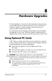
..., that may also be supplied by a PC Card manufacturer, you install all of the software or any of the Personal Computer Memory Card International Association (PCMCIA). ■ The notebook supports 32-bit (CardBus) and 16-bit PC Cards. ■ The notebook supports one Type I card or one Type... Install only the device drivers for your operating system. ■ Do not install other PC Cards. 8 Hardware Upgrades To order hardware or learn more about obtaining and installing software updates and upgrades, refer to the "Software Updates and Restorations" chapter in the Software Guide on the ...
..., that may also be supplied by a PC Card manufacturer, you install all of the software or any of the Personal Computer Memory Card International Association (PCMCIA). ■ The notebook supports 32-bit (CardBus) and 16-bit PC Cards. ■ The notebook supports one Type I card or one Type... Install only the device drivers for your operating system. ■ Do not install other PC Cards. 8 Hardware Upgrades To order hardware or learn more about obtaining and installing software updates and upgrades, refer to the "Software Updates and Restorations" chapter in the Software Guide on the ...

Hardware Guide
Page 85
... press the power button. Disconnect all applications, and shut down the notebook. 2. All other areas that you are discharged of the notebook. Hardware Upgrades Adding and Upgrading Memory Modules Å WARNING: The memory compartments are not sure whether the notebook is off or in the primary memory slot. Before beginning any procedure, ensure that require a tool to access...
... press the power button. Disconnect all applications, and shut down the notebook. 2. All other areas that you are discharged of the notebook. Hardware Upgrades Adding and Upgrading Memory Modules Å WARNING: The memory compartments are not sure whether the notebook is off or in the primary memory slot. Before beginning any procedure, ensure that require a tool to access...

Hardware Guide
Page 86
Hardware Upgrades 3. Remove any battery packs from the memory expansion slot cover. 7. Remove the screw 1 from the notebook. 6. Disconnect the power cord. 4. Removing the expansion slot cover 8. Turn the notebook upside down. 5. Hardware Guide 8-7 Tilt the expansion slot cover 2 away from the notebook. Remove the memory expansion slot cover.
Hardware Upgrades 3. Remove any battery packs from the memory expansion slot cover. 7. Remove the screw 1 from the notebook. 6. Disconnect the power cord. 4. Removing the expansion slot cover 8. Turn the notebook upside down. 5. Hardware Guide 8-7 Tilt the expansion slot cover 2 away from the notebook. Remove the memory expansion slot cover.

Hardware Guide
Page 87
b. Press the module into the slot from a 45-degree angle until it is seated, then push the board downward 2 until the retention clips snap into place. Insert the memory expansion module: a. Inserting a memory expansion module 8-8 Hardware Guide Align the keyed (notched) edge of the module 1 with the keyed area in the expansion slot. Hardware Upgrades 9.
b. Press the module into the slot from a 45-degree angle until it is seated, then push the board downward 2 until the retention clips snap into place. Insert the memory expansion module: a. Inserting a memory expansion module 8-8 Hardware Guide Align the keyed (notched) edge of the module 1 with the keyed area in the expansion slot. Hardware Upgrades 9.

Hardware Guide
Page 89
... connected to the keyboard screw. 6. Disconnect all applications, and then shut down the notebook. Remove the keyboard screw 1 from the notebook. 5. A keyboard icon is off or in the primary memory slot: 1. Remove the two Quick Launch button bezel screws 2. Save your work ,...any battery packs from the bottom of the notebook. Disconnect the power cord. 4. If you are not sure whether the notebook is located next to the notebook. 3. Hardware Upgrades Upgrading the Memory Module in the Primary Memory Slot To upgrade the memory module in Hibernation, briefly press the power...
... connected to the keyboard screw. 6. Disconnect all applications, and then shut down the notebook. Remove the keyboard screw 1 from the notebook. 5. A keyboard icon is off or in the primary memory slot: 1. Remove the two Quick Launch button bezel screws 2. Save your work ,...any battery packs from the bottom of the notebook. Disconnect the power cord. 4. If you are not sure whether the notebook is located next to the notebook. 3. Hardware Upgrades Upgrading the Memory Module in the Primary Memory Slot To upgrade the memory module in Hibernation, briefly press the power...

Hardware Guide
Page 91
Pull away the retention clips 1 on each side of the slot 2. Hardware Upgrades 9. Lift the edge of the memory expansion module, then gently pull it in a static-safe container. 8-12 Hardware Guide Remove the existing memory module: a. Removing the existing memory module ✎ To protect a memory module after it has been removed, place it out of the module. (The module tilts upward.) b.
Pull away the retention clips 1 on each side of the slot 2. Hardware Upgrades 9. Lift the edge of the memory expansion module, then gently pull it in a static-safe container. 8-12 Hardware Guide Remove the existing memory module: a. Removing the existing memory module ✎ To protect a memory module after it has been removed, place it out of the module. (The module tilts upward.) b.

Hardware Guide
Page 92
... button bezel screws located on the bottom of the module with the keyed area in the expansion slot. Insert the new memory module: a. b. Hardware Guide 8-13 Hardware Upgrades 10. Restart the notebook. Press the module 1 into the slot from a 45-degree angle until it is seated, then push the module 2 downward until the...
... button bezel screws located on the bottom of the module with the keyed area in the expansion slot. Insert the new memory module: a. b. Hardware Guide 8-13 Hardware Upgrades 10. Restart the notebook. Press the module 1 into the slot from a 45-degree angle until it is seated, then push the module 2 downward until the...

Hardware Guide
Page 93
Information about the space on the desktop, then select your hard drive. Hardware Upgrades Effects of memory in a status bar at the bottom of the window. ■ To display the amount of space required by the Hibernation file: ❏ In Windows XP, ... > Power Options icon > Hibernate tab. ❏ In Windows 2000, select Start > Settings > Control Panel > HP Power > Hibernation tab. If you experience problems with Hibernation after memory has been increased, verify that your hard drive has enough free space to accommodate a larger Hibernation file. ■ To display the amount of RAM in...
Information about the space on the desktop, then select your hard drive. Hardware Upgrades Effects of memory in a status bar at the bottom of the window. ■ To display the amount of space required by the Hibernation file: ❏ In Windows XP, ... > Power Options icon > Hibernate tab. ❏ In Windows 2000, select Start > Settings > Control Panel > HP Power > Hibernation tab. If you experience problems with Hibernation after memory has been increased, verify that your hard drive has enough free space to accommodate a larger Hibernation file. ■ To display the amount of RAM in...

Hardware Guide
Page 99
...1-10 low-battery conditions, identifying 3-16 M magnetic fields, protecting drives from 4-1 maximum altitude 9-1 memory adding memory expansion board 8-6 expansion compartment 8-6 primary slot 1-3, 8-6 upgrading primary board 8-10 memory expansion compartment 1-9 microphone input jack 1-4, 5-2 microphone, internal 1-6, 5-2 Mini PCI (Peripheral Component Interconnect),...from 2-5, 7-2 overhead projector (optional), external monitor connector 1-7 P PAL, PAL-M television formats 5-5 PC Card inserting 8-2 stopping 8-3 zoomed video 8-1 PC Card eject button 1-4 PC Card slot 1-4 Index-4 Hardware Guide
...1-10 low-battery conditions, identifying 3-16 M magnetic fields, protecting drives from 4-1 maximum altitude 9-1 memory adding memory expansion board 8-6 expansion compartment 8-6 primary slot 1-3, 8-6 upgrading primary board 8-10 memory expansion compartment 1-9 microphone input jack 1-4, 5-2 microphone, internal 1-6, 5-2 Mini PCI (Peripheral Component Interconnect),...from 2-5, 7-2 overhead projector (optional), external monitor connector 1-7 P PAL, PAL-M television formats 5-5 PC Card inserting 8-2 stopping 8-3 zoomed video 8-1 PC Card eject button 1-4 PC Card slot 1-4 Index-4 Hardware Guide


