

Reference Guide
Page 9
... CMOS...8-8 8.2.9 ACCESSING CMOS FEATURE BITS 8-8 8.2.10 SECURITY FUNCTIONS 8-10 8.3 MEMORY DETECTION AND CONFIGURATION 8-11 8.4 PNP SUPPORT ...8-12 8.4.1 SMBIOS...8-13 8.5 POWER MANAGEMENT FUNCTIONS 8-14 8.5.1 INDEPENDENT PM SUPPORT 8-14 8.5.2 ACPI SUPPORT...8-15 8.5.3 APM 1.2 SUPPORT ...8-15 8.6 USB LEGACY SUPPORT 8-17 8.7 BIOS UPGRADING...8-18 APPENDIX A ERROR MESSAGES AND CODES A.1 A.2 A.3 A.4 A.5 A.6 A.7 A.8 A.9 A.10 A.11 A.12 A.13 A.14 A.15 A.16 A.17 A.18 A.19 A.20 A.21 A.22 A.23 INTRODUCTION...A-1 POWER-ON MESSAGES...A-1 BEEP/KEYBOARD LED CODES A-1 POWER-ON SELF TEST...
... CMOS...8-8 8.2.9 ACCESSING CMOS FEATURE BITS 8-8 8.2.10 SECURITY FUNCTIONS 8-10 8.3 MEMORY DETECTION AND CONFIGURATION 8-11 8.4 PNP SUPPORT ...8-12 8.4.1 SMBIOS...8-13 8.5 POWER MANAGEMENT FUNCTIONS 8-14 8.5.1 INDEPENDENT PM SUPPORT 8-14 8.5.2 ACPI SUPPORT...8-15 8.5.3 APM 1.2 SUPPORT ...8-15 8.6 USB LEGACY SUPPORT 8-17 8.7 BIOS UPGRADING...8-18 APPENDIX A ERROR MESSAGES AND CODES A.1 A.2 A.3 A.4 A.5 A.6 A.7 A.8 A.9 A.10 A.11 A.12 A.13 A.14 A.15 A.16 A.17 A.18 A.19 A.20 A.21 A.22 A.23 INTRODUCTION...A-1 POWER-ON MESSAGES...A-1 BEEP/KEYBOARD LED CODES A-1 POWER-ON SELF TEST...

Reference Guide
Page 13
Technical Reference Guide LIST OF TABLES TABLE 1-1. ARCHITECTURAL COMPARISON 2-8 TABLE 2-3. SPD ADDRESS MAP (SDRAM DIMM 3-6 TABLE 3-4. MASKABLE INTERRUPT CONTROL REGISTERS 4-13 TABLE 4-7. CLOCK GENERATION AND DISTRIBUTION 4-16 TABLE 4-10. PARALLEL INTERFACE CONFIGURATION REGISTERS 5-10 TABLE 5-9. USB CONNECTOR PINOUT 5-25 TABLE 5-18. MULTIBAY 24X CD-ROM DRIVE SPECIFICATIONS 2-17 TABLE 2-10. HOST/PCI BRIDGE CONFIGURATION REGISTERS (GMCH, FUNCTION 0 3-8 TABLE 4-1. SYSTEM BOARD PCI DEVICE IDENTIFICATION 4-5 TABLE 4-3. SERIAL INTERFACE CONTROL REGISTERS...
Technical Reference Guide LIST OF TABLES TABLE 1-1. ARCHITECTURAL COMPARISON 2-8 TABLE 2-3. SPD ADDRESS MAP (SDRAM DIMM 3-6 TABLE 3-4. MASKABLE INTERRUPT CONTROL REGISTERS 4-13 TABLE 4-7. CLOCK GENERATION AND DISTRIBUTION 4-16 TABLE 4-10. PARALLEL INTERFACE CONFIGURATION REGISTERS 5-10 TABLE 5-9. USB CONNECTOR PINOUT 5-25 TABLE 5-18. MULTIBAY 24X CD-ROM DRIVE SPECIFICATIONS 2-17 TABLE 2-10. HOST/PCI BRIDGE CONFIGURATION REGISTERS (GMCH, FUNCTION 0 3-8 TABLE 4-1. SYSTEM BOARD PCI DEVICE IDENTIFICATION 4-5 TABLE 4-3. SERIAL INTERFACE CONTROL REGISTERS...

Reference Guide
Page 14
... 5-24. CMOS FEATURE BITS ...8-9 TABLE 8-3. POWER-ON SELF TEST (POST) MESSAGES A-2 TABLE A-4. HARD DRIVE ERROR MESSAGES A-8 TABLE A-14. AUDIO ERROR MESSAGES A-10 TABLE A-17. BEEP/KEYBOARD LED CODES A-1 TABLE A-3. SYSTEM STATUS ERROR MESSAGES A-8 TABLE A-13. AC'97 AUDIO CODEC CONTROL REGISTERS 5-30 TABLE 5-21. DB-15 MONITOR CONNECTOR PINOUT 6-6 TABLE 8-1. Technical Reference Guide TABLE 5-19. AC'97 AUDIO CONTROLLER PCI CONFIGURATION REGISTERS 5-30 TABLE 5-20. AOL EVENTS ...5-33 TABLE 5-23. PCI CONFIGURATION SPACE REGISTERS 6-5 TABLE 6-3. MONITOR POWER MANAGEMENT...
... 5-24. CMOS FEATURE BITS ...8-9 TABLE 8-3. POWER-ON SELF TEST (POST) MESSAGES A-2 TABLE A-4. HARD DRIVE ERROR MESSAGES A-8 TABLE A-14. AUDIO ERROR MESSAGES A-10 TABLE A-17. BEEP/KEYBOARD LED CODES A-1 TABLE A-3. SYSTEM STATUS ERROR MESSAGES A-8 TABLE A-13. AC'97 AUDIO CODEC CONTROL REGISTERS 5-30 TABLE 5-21. DB-15 MONITOR CONNECTOR PINOUT 6-6 TABLE 8-1. Technical Reference Guide TABLE 5-19. AC'97 AUDIO CONTROLLER PCI CONFIGURATION REGISTERS 5-30 TABLE 5-20. AOL EVENTS ...5-33 TABLE 5-23. PCI CONFIGURATION SPACE REGISTERS 6-5 TABLE 6-3. MONITOR POWER MANAGEMENT...

Reference Guide
Page 18
... disk system carry flag color graphics adapter channel centimeter cache/memory controller complimentary metal-oxide semiconductor (configuration memory) controller control compressor/decompressor Compaq central processing unit cathode ray tube Compaq system management / Compaq server management Configure to order direct access arrangement digital-to-analog converter direct current DOS compatibility hole Display Data Channel direction flag Continued Compaq iPAQ Family of Internet Devices 1-3 First Edition - Technical Reference Guide 1.4 COMMON ACRONYMS AND ABBREVIATIONS Table 1-1 lists...
... disk system carry flag color graphics adapter channel centimeter cache/memory controller complimentary metal-oxide semiconductor (configuration memory) controller control compressor/decompressor Compaq central processing unit cathode ray tube Compaq system management / Compaq server management Configure to order direct access arrangement digital-to-analog converter direct current DOS compatibility hole Display Data Channel direction flag Continued Compaq iPAQ Family of Internet Devices 1-3 First Edition - Technical Reference Guide 1.4 COMMON ACRONYMS AND ABBREVIATIONS Table 1-1 lists...

Reference Guide
Page 20
... pulse code modulation Internet Device Memory Card International Association parity flag personal identification number Programmed I/O power-on self test programmable read-only memory pointer random access memory row address strobe receiver resume flag red/green/blue (monitor input) Relative humidity RDRAM inline memory module root mean square read-only memory revolutions per minute real time clock read/write Continued Compaq iPAQ Family of Internet Devices 1-5 First Edition - Technical Reference Guide Table...
... pulse code modulation Internet Device Memory Card International Association parity flag personal identification number Programmed I/O power-on self test programmable read-only memory pointer random access memory row address strobe receiver resume flag red/green/blue (monitor input) Relative humidity RDRAM inline memory module root mean square read-only memory revolutions per minute real time clock read/write Continued Compaq iPAQ Family of Internet Devices 1-5 First Edition - Technical Reference Guide Table...
Reference Guide
Page 24
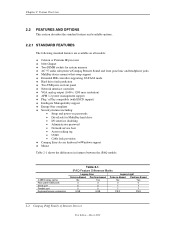
...MultiBay hard drive • I/O interface disabling • Administrator password • Network service boot • Asset tracking tag • UUID • Cable lock provision ♦ Compaq Easy-Access keyboard w/Windows support ♦ Mouse Table 2-1 shows the differences in features between the iPAQ models: Table 2-1. Feature Difference Matrix 4-MB Display cache Rear panel USB ports Serial port Parallel port Keyboard/mouse connection Table 2-1. March 2000 iPAQ Feature Difference Matrix Legacy-Free Celeron-Based Pentium-based No Yes 3 3 0 0 0 0 USB USB Legacy-Light...
...MultiBay hard drive • I/O interface disabling • Administrator password • Network service boot • Asset tracking tag • UUID • Cable lock provision ♦ Compaq Easy-Access keyboard w/Windows support ♦ Mouse Table 2-1 shows the differences in features between the iPAQ models: Table 2-1. Feature Difference Matrix 4-MB Display cache Rear panel USB ports Serial port Parallel port Keyboard/mouse connection Table 2-1. March 2000 iPAQ Feature Difference Matrix Legacy-Free Celeron-Based Pentium-based No Yes 3 3 0 0 0 0 USB USB Legacy-Light...

Reference Guide
Page 29
...3 BIOS ROM configuration jumper 4 Speaker connector 5 Audio microphone/headphone header 6 Audio line out jack 7 Audio line in jack 8 Network connector 9 VGA monitor connector 10 Parallel I/F connector 11 Serial I/F connector 12 USB ports 0, 1, 2 connectors 13 PS/2 mouse connector (top), PS/2 keyboard connector (bottom) 14 Serial I/F header 15 PGA370 processor socket 16 DIMM sockets 17 Processor (boxed) fan header 18 IDE (primary) 40-pin connector 19 IDE (secondary) 50-pin connector 20 Power button/LED indicator connector 21 CD audio header 22 Power supply...
...3 BIOS ROM configuration jumper 4 Speaker connector 5 Audio microphone/headphone header 6 Audio line out jack 7 Audio line in jack 8 Network connector 9 VGA monitor connector 10 Parallel I/F connector 11 Serial I/F connector 12 USB ports 0, 1, 2 connectors 13 PS/2 mouse connector (top), PS/2 keyboard connector (bottom) 14 Serial I/F header 15 PGA370 processor socket 16 DIMM sockets 17 Processor (boxed) fan header 18 IDE (primary) 40-pin connector 19 IDE (secondary) 50-pin connector 20 Power button/LED indicator connector 21 CD audio header 22 Power supply...

Reference Guide
Page 35
... Technical Reference Guide 2.4.3 SUPPORT COMPONENTS Input/output functions not provided by the chipset are provided and accessible through an access opening once the right side cover has been removed. Two DIMM sockets are handled by the support components. Support Component Functions Table 2-4. Support Component Functions Component Name LPC47B277 I/O Controller AD1881 Audio Codec 82559 Ethernet Controller [1] Function Keyboard and pointing device I/F Diskette I/F Serial I/F Parallel I/F AGP, PCI reset generation ISA serial IRQ converter Power button...
... Technical Reference Guide 2.4.3 SUPPORT COMPONENTS Input/output functions not provided by the chipset are provided and accessible through an access opening once the right side cover has been removed. Two DIMM sockets are handled by the support components. Support Component Functions Table 2-4. Support Component Functions Component Name LPC47B277 I/O Controller AD1881 Audio Codec 82559 Ethernet Controller [1] Function Keyboard and pointing device I/F Diskette I/F Serial I/F Parallel I/F AGP, PCI reset generation ISA serial IRQ converter Power button...

Reference Guide
Page 36
... be disabled through a DB-25 connector. Pentium III-based systems also include 4 megabytes of local display cache for higher 3D performance. 2-14 Compaq iPAQ Family of mass storage devices except for removeable hard drives. 2.4.6 SERIAL AND PARALLEL INTERFACES The legacy-light models include a serial port and a parallel port accessible at the rear of the 810e chipset. This system uses SMART drives for peripherals. The USB provides hot plugging/unplugging (Plug 'n Play) functionality. 2.4.8 GRAPHICS...
... be disabled through a DB-25 connector. Pentium III-based systems also include 4 megabytes of local display cache for higher 3D performance. 2-14 Compaq iPAQ Family of mass storage devices except for removeable hard drives. 2.4.6 SERIAL AND PARALLEL INTERFACES The legacy-light models include a serial port and a parallel port accessible at the rear of the 810e chipset. This system uses SMART drives for peripherals. The USB provides hot plugging/unplugging (Plug 'n Play) functionality. 2.4.8 GRAPHICS...

Reference Guide
Page 45
... each installed DIMM. The SPD format as part number and serial number. If ECC DIMMs are 2, 9, 10, 18, 23, and 24. The memory interface consists of a 64-bit data bus operating at 100 MHz regardless of time during POST by the system BIOS using non-ECC DIMMs only. Technical Reference Guide 3.3 MEMORY SUBSYSTEM The 810e chipset supports PC100 SDRAM for ECC benefits (error logging...
... each installed DIMM. The SPD format as part number and serial number. If ECC DIMMs are 2, 9, 10, 18, 23, and 24. The memory interface consists of a 64-bit data bus operating at 100 MHz regardless of time during POST by the system BIOS using non-ECC DIMMs only. Technical Reference Guide 3.3 MEMORY SUBSYSTEM The 810e chipset supports PC100 SDRAM for ECC benefits (error logging...

Reference Guide
Page 66
... memory tested 19h Hard drive 1, primary controller 32h Century 1Ah Hard drive 2, primary controller 33h Miscellaneous flags set by pressing and releasing the Power button, then pressing and holding the power button for clearing the contents of the 82802 FWH. Should the system hang during boot as the result of corrupted CMOS data, then a Power Button Override boot should detect the occurrence of Internet Devices First Edition - The system should be accessed using port...
... memory tested 19h Hard drive 1, primary controller 32h Century 1Ah Hard drive 2, primary controller 33h Miscellaneous flags set by pressing and releasing the Power button, then pressing and holding the power button for clearing the contents of the 82802 FWH. Should the system hang during boot as the result of corrupted CMOS data, then a Power Button Override boot should detect the occurrence of Internet Devices First Edition - The system should be accessed using port...

Reference Guide
Page 74
... 2 Error Detect 1 Row 1 Error Detect 0 Row 0 Error Detect 0 = No single bit error detected. 1 = Single bit error detected. Refer to Chapter 8 for more information on password. 4.7.3 CMOS FEATURE BITS Configuration memory above location 3Fh is used for storing special features that are accessed using BIOS function INT15, AX=E845h. Configuration Byte 37h-3Fh, Power-On Password These eight locations hold the power-on accessing the feature bits with BIOS. 4-26 Compaq iPAQ Family of Internet Devices...
... 2 Error Detect 1 Row 1 Error Detect 0 Row 0 Error Detect 0 = No single bit error detected. 1 = Single bit error detected. Refer to Chapter 8 for more information on password. 4.7.3 CMOS FEATURE BITS Configuration memory above location 3Fh is used for storing special features that are accessed using BIOS function INT15, AX=E845h. Configuration Byte 37h-3Fh, Power-On Password These eight locations hold the power-on accessing the feature bits with BIOS. 4-26 Compaq iPAQ Family of Internet Devices...
Reference Guide
Page 76
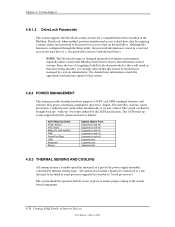
... hard drive installed in some processor upgrade kits (known as a part of the power supply assembly) controlled by a system administrator. Although this feature be included in the Multibay. The system should be brought back up ("wake-up events supported by user control. Chapter 4 System Support 4.8.1.2 DriveLock Passwords This system supports the DriveLock security feature for access to ensure proper cooling of the system board components. 4-28 Compaq iPAQ Family of Internet Devices...
... hard drive installed in some processor upgrade kits (known as a part of the power supply assembly) controlled by a system administrator. Although this feature be included in the Multibay. The system should be brought back up ("wake-up events supported by user control. Chapter 4 System Support 4.8.1.2 DriveLock Passwords This system supports the DriveLock security feature for access to ensure proper cooling of the system board components. 4-28 Compaq iPAQ Family of Internet Devices...
Reference Guide
Page 110
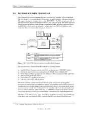
...: ♦ Intel 82559 Fast Ethernet controller with 32-bit architecture and 3-KB TX/RX buffers. ♦ Dual-mode support with auto-switching between 10BASE-T and 100BASE-TX. ♦ Power down . 5-32 Compaq iPAQ Family of Internet Devices First Edition - or full-duplex modes, and provides auto-negotiation of overrun while waiting for networks that can operate in the system (BIOS) ROM. March 2000 Transmit and receive...
...: ♦ Intel 82559 Fast Ethernet controller with 32-bit architecture and 3-KB TX/RX buffers. ♦ Dual-mode support with auto-switching between 10BASE-T and 100BASE-TX. ♦ Power down . 5-32 Compaq iPAQ Family of Internet Devices First Edition - or full-duplex modes, and provides auto-negotiation of overrun while waiting for networks that can operate in the system (BIOS) ROM. March 2000 Transmit and receive...
Reference Guide
Page 127
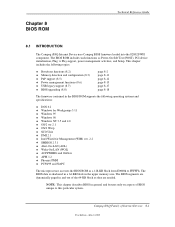
... BIOS ROM as Power-On Self Test (POST), PCI device initialization, Plug 'n Play support, power management activities, and Setup. The BIOS segments are dynamically paged in the BIOS ROM supports the following topics: ♦ Boot/reset functions (8.2) ♦ Memory detection and configuration (8.3) ♦ PnP support (8.5) ♦ Power management functions (8.6) ♦ USB legacy support (8.7) ♦ BIOS upgrading (8.8) page 8-2 page 8-11 page 8-12 page 8-15 page 8-17 page 8-18 The firmware contained in and out of Internet Devices 8-1 First Edition - Technical Reference Guide...
... BIOS ROM as Power-On Self Test (POST), PCI device initialization, Plug 'n Play support, power management activities, and Setup. The BIOS segments are dynamically paged in the BIOS ROM supports the following topics: ♦ Boot/reset functions (8.2) ♦ Memory detection and configuration (8.3) ♦ PnP support (8.5) ♦ Power management functions (8.6) ♦ USB legacy support (8.7) ♦ BIOS upgrading (8.8) page 8-2 page 8-11 page 8-12 page 8-15 page 8-17 page 8-18 The firmware contained in and out of Internet Devices 8-1 First Edition - Technical Reference Guide...

Reference Guide
Page 136
... diskette drive, power drive (SCSI and/or ATAPI), and floptical drive installed will be issued by a remote system (over a network). Client management software should check the following security features: ♦ QuickLock ♦ IDE controller disable ♦ Serial port disable (legacy-light only) ♦ Parallel port disable (legacy-light only) ♦ Change administrator password ♦ QuickLock on suspend ♦ Ownership tag ♦ USB disable (legacy-light only) The write-protect function that use removable read/write media...
... diskette drive, power drive (SCSI and/or ATAPI), and floptical drive installed will be issued by a remote system (over a network). Client management software should check the following security features: ♦ QuickLock ♦ IDE controller disable ♦ Serial port disable (legacy-light only) ♦ Parallel port disable (legacy-light only) ♦ Change administrator password ♦ QuickLock on suspend ♦ Ownership tag ♦ USB disable (legacy-light only) The write-protect function that use removable read/write media...

Reference Guide
Page 146
... Full PCI I/O Port Conflict PCI Memory Conflict Primary Boot Device Not Found Primary IDE Cntrl. BIOS cannot access drive B: Gate A20 of jumper. A-2 Compaq Personal Computers Changed - Keyboard controller failure. Parallel port has requested a resource already in use . A non-PnP ISA card has requested a resource already in use . Power-On Self Test (POST) Messages Error Message Bad PnP Serial ID Checksum Address Lines Short! Boot disk in master DMA controller. Diskette drive controller has requested a resource already in CMOS...
... Full PCI I/O Port Conflict PCI Memory Conflict Primary Boot Device Not Found Primary IDE Cntrl. BIOS cannot access drive B: Gate A20 of jumper. A-2 Compaq Personal Computers Changed - Keyboard controller failure. Parallel port has requested a resource already in use . A non-PnP ISA card has requested a resource already in use . Power-On Self Test (POST) Messages Error Message Bad PnP Serial ID Checksum Address Lines Short! Boot disk in master DMA controller. Diskette drive controller has requested a resource already in CMOS...

Reference Guide
Page 152
... to reset controller Fatal error while reading Fatal error while writing Failed compare of R/W buffers Failed to format a track Failed diskette sector wrap during read media in file write test Failed I /O compare test Failed drive/head register test Failed digital input register test Cylinder 1 error Failed controller RAM diagnostics Failed controller-to-drive diagnostics Failed to write sector buffer Failed to read Cntlr. controller failure 1793-xx = Sec. Hard Drive Error Messages...
... to reset controller Fatal error while reading Fatal error while writing Failed compare of R/W buffers Failed to format a track Failed diskette sector wrap during read media in file write test Failed I /O compare test Failed drive/head register test Failed digital input register test Cylinder 1 error Failed controller RAM diagnostics Failed controller-to-drive diagnostics Failed to write sector buffer Failed to read Cntlr. controller failure 1793-xx = Sec. Hard Drive Error Messages...
Reference Guide
Page 175
... CMOS, clearing, 4-18 codec, audio, 5-29 Configuration Cycle, 4-4 configuration cycle (PCI), 4-4 configuration memory, 4-17 configuration space (PCI), 4-5 Connector Audio, CD, 5-27 audio, headphones out, 5-26 audio, line in, 5-26 audio, line out, 5-26 Audio, Mic In, 5-26 Audio, Speaker, 5-27 display (VGA monitor), 6-6 IDE interface, 5-3 IDE interface (CD-ROM), 5-4 keyboard/pointing device interface, 5-21 Network RJ-45, 5-36 parallel interface, 5-14 serial interface (RS-232), 5-5, 5-6 Connector (cont) Universal Serial Bus interface, 5-25 cooling, 4-28 core voltage, 3-2, 3-3 Desktop Management...
... CMOS, clearing, 4-18 codec, audio, 5-29 Configuration Cycle, 4-4 configuration cycle (PCI), 4-4 configuration memory, 4-17 configuration space (PCI), 4-5 Connector Audio, CD, 5-27 audio, headphones out, 5-26 audio, line in, 5-26 audio, line out, 5-26 Audio, Mic In, 5-26 Audio, Speaker, 5-27 display (VGA monitor), 6-6 IDE interface, 5-3 IDE interface (CD-ROM), 5-4 keyboard/pointing device interface, 5-21 Network RJ-45, 5-36 parallel interface, 5-14 serial interface (RS-232), 5-5, 5-6 Connector (cont) Universal Serial Bus interface, 5-25 cooling, 4-28 core voltage, 3-2, 3-3 Desktop Management...

Reference Guide
Page 176
... supply, 7-5 Specifications 24x CD-ROM Drive, 2-16, 2-17 Audio subsystem, 5-31 Hard Drive, 2-18 specifications, system, 2-15 SSE, 3-3 system board, 2-7 system ID, 8-4 system information table (SIT), 8-4 system memory, 2-13, 3-5 system ROM, 8-1 thermal sensing, 4-28 timer, interval, 4-16 typematic, C-8 UART, 5-5 Universal Serial Bus (USB) interface, 5-22 upggrading BIOS, 8-18 upgrading embedded graphics, 6-4 upgrading, processor, 2-11, 3-4 USB interface, 5-22 USB keyboard, C-4 USB legacy support, 8-17 USB ports, 2-14 video BIOS, 6-3 voltage, core, 3-2, 3-3 wake up events, 7-3 wake up, remote...
... supply, 7-5 Specifications 24x CD-ROM Drive, 2-16, 2-17 Audio subsystem, 5-31 Hard Drive, 2-18 specifications, system, 2-15 SSE, 3-3 system board, 2-7 system ID, 8-4 system information table (SIT), 8-4 system memory, 2-13, 3-5 system ROM, 8-1 thermal sensing, 4-28 timer, interval, 4-16 typematic, C-8 UART, 5-5 Universal Serial Bus (USB) interface, 5-22 upggrading BIOS, 8-18 upgrading embedded graphics, 6-4 upgrading, processor, 2-11, 3-4 USB interface, 5-22 USB keyboard, C-4 USB legacy support, 8-17 USB ports, 2-14 video BIOS, 6-3 voltage, core, 3-2, 3-3 wake up events, 7-3 wake up, remote...


