Maintenance and Service Guide
Page 6
Packaging and transporting guidelines 36 Component replacement procedures 38 Service tag ...38 Computer feet ...39 Battery ...40 Optical drive (select models only 41 WLAN module ...43 Memory module ...45 Hard drive ...46 Keyboard ...49 Top cover ...52 Power button ...TouchPad button board ...57 USB board ...59 Power connector cable ...60 Speakers ...62 Optical drive connector cable 63 Display assembly ...64 System board ...71 RTC battery ...74 Fan/heat sink assembly ...76 Processor ...82 5 Setup Utility (BIOS) and System Diagnostics 84 Using Setup Utility ...84 Starting Setup Utility ...84 ...
Packaging and transporting guidelines 36 Component replacement procedures 38 Service tag ...38 Computer feet ...39 Battery ...40 Optical drive (select models only 41 WLAN module ...43 Memory module ...45 Hard drive ...46 Keyboard ...49 Top cover ...52 Power button ...TouchPad button board ...57 USB board ...59 Power connector cable ...60 Speakers ...62 Optical drive connector cable 63 Display assembly ...64 System board ...71 RTC battery ...74 Fan/heat sink assembly ...76 Processor ...82 5 Setup Utility (BIOS) and System Diagnostics 84 Using Setup Utility ...84 Starting Setup Utility ...84 ...
Maintenance and Service Guide
Page 7
... to a previous date and time 98 8 Power cord set requirements ...99 Requirements for all countries ...99 Requirements for specific countries and regions 100 9 Recycling ...101 Battery ...101 Display ...101 Index ...107 vii
... to a previous date and time 98 8 Power cord set requirements ...99 Requirements for all countries ...99 Requirements for specific countries and regions 100 9 Recycling ...101 Battery ...101 Display ...101 Index ...107 vii

Maintenance and Service Guide
Page 14
...on computer models equipped with ground pin, supports 3-pin DC connector) Support for the following batteries: √ √ ● 6-cell, 55-Whr, 2.55-Ah Li-ion battery ● 6-cell, 47-Whr, 2.20-Ah Li-ion battery Security Security cable slot √ √ Operating system Preinstalled: √ √ &#...with a 500-GB hard drive) ● FreeDOS Serviceability End-user replaceable parts: √ √ ● AC adapter ● Battery ● Hard drive ● Memory modules (2) ● Optical drive ● WLAN module 6 Chapter 1 Product description
...on computer models equipped with ground pin, supports 3-pin DC connector) Support for the following batteries: √ √ ● 6-cell, 55-Whr, 2.55-Ah Li-ion battery ● 6-cell, 47-Whr, 2.20-Ah Li-ion battery Security Security cable slot √ √ Operating system Preinstalled: √ √ &#...with a 500-GB hard drive) ● FreeDOS Serviceability End-user replaceable parts: √ √ ● AC adapter ● Battery ● Hard drive ● Memory modules (2) ● Optical drive ● WLAN module 6 Chapter 1 Product description

Maintenance and Service Guide
Page 21
.... ● White: The computer is connected to the computer. Connect optional USB devices. Attaches an optional security cable to external power and the battery is fully charged. ● Amber: A battery is idle. NOTE: The security cable is designed to an optical disc. ● On: The optical drive is in use. ● Off...
.... ● White: The computer is connected to the computer. Connect optional USB devices. Attaches an optional security cable to external power and the battery is fully charged. ● Amber: A battery is idle. NOTE: The security cable is designed to an optical disc. ● On: The optical drive is in use. ● Off...

Maintenance and Service Guide
Page 22
NOTE: The computer fan starts up automatically to cycle on and off during routine operation. Bottom Item (1) (2) (3) (4) (5) Component Battery bay Battery release latch Vents (5) Hard drive bay Memory module compartment Description Holds the battery. Contains the memory module slots. 14 Chapter 2 External component identification It is normal for the internal fan to cool internal components and prevent overheating. Releases the battery from the battery bay. Enable airflow to cool internal components. Holds the hard drive.
NOTE: The computer fan starts up automatically to cycle on and off during routine operation. Bottom Item (1) (2) (3) (4) (5) Component Battery bay Battery release latch Vents (5) Hard drive bay Memory module compartment Description Holds the battery. Contains the memory module slots. 14 Chapter 2 External component identification It is normal for the internal fan to cool internal components and prevent overheating. Releases the battery from the battery bay. Enable airflow to cool internal components. Holds the hard drive.
Maintenance and Service Guide
Page 27
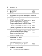
... memory (for use only with computer models in the United States) For use only with computer models equipped with an Intel processor 646135-001 RTC battery (includes cable and double-sided tape) 646132-001 Processor (includes replacement thermal material): Intel Core i5-2450M 2.50-GHz processor (1333-MHz FSB, 3.0-MB L3...
... memory (for use only with computer models in the United States) For use only with computer models equipped with an Intel processor 646135-001 RTC battery (includes cable and double-sided tape) 646132-001 Processor (includes replacement thermal material): Intel Core i5-2450M 2.50-GHz processor (1333-MHz FSB, 3.0-MB L3...

Maintenance and Service Guide
Page 29
... Super Multi Double-Layer Combo Drive with UMA video memory 646184-001 Base enclosure (includes battery release latch, heat sink, replacement thermal material, and 4 rubber feet) 646114-001 Battery: 6-cell, 55-Whr, 2.55-Ah Li-ion battery 593554-001 6-cell, 47-Whr, 2.20-Ah Li-ion battery 593553-001 Optical drive (select models only;
... Super Multi Double-Layer Combo Drive with UMA video memory 646184-001 Base enclosure (includes battery release latch, heat sink, replacement thermal material, and 4 rubber feet) 646114-001 Battery: 6-cell, 55-Whr, 2.55-Ah Li-ion battery 593554-001 6-cell, 47-Whr, 2.20-Ah Li-ion battery 593553-001 Optical drive (select models only;

Maintenance and Service Guide
Page 35
... AR9002WB-1NGB 802.11b/g/n 1×1 WiFi and Bluetooth 2.1+EDR Combo Adapter (BT3.0+HS ready) 6-cell, 47-Whr, 2.20-Ah Li-ion battery 6-cell, 55-Whr, 2.55-Ah Li-ion battery Realtek 8188BC8 802.11a/b/g/n 2×2 WiFi and Bluetooth 3.0+HS Combo Adapter 640-GB, 5400-rpm hard drive (2.5-in India (3pin, black, 1.83...
... AR9002WB-1NGB 802.11b/g/n 1×1 WiFi and Bluetooth 2.1+EDR Combo Adapter (BT3.0+HS ready) 6-cell, 47-Whr, 2.20-Ah Li-ion battery 6-cell, 55-Whr, 2.55-Ah Li-ion battery Realtek 8188BC8 802.11a/b/g/n 2×2 WiFi and Bluetooth 3.0+HS Combo Adapter 640-GB, 5400-rpm hard drive (2.5-in India (3pin, black, 1.83...

Maintenance and Service Guide
Page 36
... drive (2.5-in , HD, LED, BrightView display panel Microphone module Antenna Kit (includes left and right wireless antenna cables and transceivers) Display enclosure Base enclosure (includes battery release latch, heat sink, replacement thermal material, and 4 rubber feet) Display bezel for use with computer models equipped with a webcam and a microphone Display bezel for...
... drive (2.5-in , HD, LED, BrightView display panel Microphone module Antenna Kit (includes left and right wireless antenna cables and transceivers) Display enclosure Base enclosure (includes battery release latch, heat sink, replacement thermal material, and 4 rubber feet) Display bezel for use with computer models equipped with a webcam and a microphone Display bezel for...

Maintenance and Service Guide
Page 38
... (includes replacement thermal material) Speaker Kit (includes left and right speakers and cable) Fan/heat sink assembly for more Plastics Kit spare part information. RTC battery (includes cable and double-sided tape) Screw Kit Display Screw Kit (includes Mylar screw covers and screws) Thermal Material Kit for use only with computer...
... (includes replacement thermal material) Speaker Kit (includes left and right speakers and cable) Fan/heat sink assembly for more Plastics Kit spare part information. RTC battery (includes cable and double-sided tape) Screw Kit Display Screw Kit (includes Mylar screw covers and screws) Thermal Material Kit for use only with computer...

Maintenance and Service Guide
Page 48
...down through the operating system. 2. Shut down into place.) 40 Chapter 4 Removal and replacement procedures Slide the battery release latch (1) to the computer. 3. To insert the battery: 1. Disconnect the power from the computer by first unplugging the power cord from the AC outlet and then...on the rear edge of the battery bay. 2. Battery Description 6-cell, 55-Whr, 2.55-Ah Li-ion battery 6-cell, 47-Whr, 2.20-Ah Li-ion battery Spare part number 593554-001 593553-001 Before disassembling the computer, follow these steps: 1. Remove the battery (3) from the computer. Disconnect ...
...down through the operating system. 2. Shut down into place.) 40 Chapter 4 Removal and replacement procedures Slide the battery release latch (1) to the computer. 3. To insert the battery: 1. Disconnect the power from the computer by first unplugging the power cord from the AC outlet and then...on the rear edge of the battery bay. 2. Battery Description 6-cell, 55-Whr, 2.55-Ah Li-ion battery 6-cell, 47-Whr, 2.20-Ah Li-ion battery Spare part number 593554-001 593553-001 Before disassembling the computer, follow these steps: 1. Remove the battery (3) from the computer. Disconnect ...

Maintenance and Service Guide
Page 49
... unsure whether the computer is off or in Hibernation, turn the computer on page 40). Disconnect all external devices connected to the computer. 2. Remove the battery (see Battery on , and then shut it rests at an angle. Remove the optical drive: 1. Lift the rear edge of the memory module/wireless module compartment...
... unsure whether the computer is off or in Hibernation, turn the computer on page 40). Disconnect all external devices connected to the computer. 2. Remove the battery (see Battery on , and then shut it rests at an angle. Remove the optical drive: 1. Lift the rear edge of the memory module/wireless module compartment...

Maintenance and Service Guide
Page 51
...Phillips PM2.0×3.0 screw (2) that regulates wireless devices in your country or region. Remove the memory module/wireless module compartment cover (see Battery on page 40). 5. Before removing the WLAN module, follow these steps: 1. If you replace the module and then receive a warning... the WLAN module #2 terminal. 2. Disconnect all external devices connected to restore device functionality, and then contact technical support. Remove the battery (see Optical drive (select models only) on page 41). WLAN module Description Atheros 9485GN 802.11b/g/n 1×1 WiFi and 3012 ...
...Phillips PM2.0×3.0 screw (2) that regulates wireless devices in your country or region. Remove the memory module/wireless module compartment cover (see Battery on page 40). 5. Before removing the WLAN module, follow these steps: 1. If you replace the module and then receive a warning... the WLAN module #2 terminal. 2. Disconnect all external devices connected to restore device functionality, and then contact technical support. Remove the battery (see Optical drive (select models only) on page 41). WLAN module Description Atheros 9485GN 802.11b/g/n 1×1 WiFi and 3012 ...

Maintenance and Service Guide
Page 53
...from the computer by pulling it down the computer. Disconnect all external devices connected to install a memory module. Remove the memory module: 1. Remove the battery (see Optical drive (select models only) on , and then shut it away from the computer. 4. Component replacement procedures 45 Spread the retaining tabs (1)..., turn the computer on page 41). Reverse this procedure to the computer. 3. Remove the memory module/wireless module compartment cover (see Battery on each side of the memory module slot to release the memory module. (The memory module tilts up.) 2.
...from the computer by pulling it down the computer. Disconnect all external devices connected to install a memory module. Remove the memory module: 1. Remove the battery (see Optical drive (select models only) on , and then shut it away from the computer. 4. Component replacement procedures 45 Spread the retaining tabs (1)..., turn the computer on page 41). Reverse this procedure to the computer. 3. Remove the memory module/wireless module compartment cover (see Battery on each side of the memory module slot to release the memory module. (The memory module tilts up.) 2.

Maintenance and Service Guide
Page 54
...GB, 5400-rpm Spare part number 603785-001 634932-001 622643-001 622641-001 Before removing the hard drive, follow these steps: 1. Remove the battery (see Optical drive (select models only) on page 40). 5. The hard drive bracket and screws are unsure whether the computer is included in the... included in Hibernation, turn the computer on, and then shut it down the computer. Remove the memory module/wireless module compartment cover (see Battery on page 41). The hard drive connector cable is off or in the Hard Drive Hardware Kit, spare part number 646122-001. Disconnect the...
...GB, 5400-rpm Spare part number 603785-001 634932-001 622643-001 622641-001 Before removing the hard drive, follow these steps: 1. Remove the battery (see Optical drive (select models only) on page 40). 5. The hard drive bracket and screws are unsure whether the computer is included in the... included in Hibernation, turn the computer on, and then shut it down the computer. Remove the memory module/wireless module compartment cover (see Battery on page 41). The hard drive connector cable is off or in the Hard Drive Hardware Kit, spare part number 646122-001. Disconnect the...

Maintenance and Service Guide
Page 57
... only with computer models equipped with all external devices connected to the computer. 3. Keyboard NOTE: The keyboard spare part kit includes a keyboard cable. Remove the battery (see Battery on , and then shut it down the computer. Remove the memory module/wireless module compartment cover (see Hard drive on page 41). 6. Disconnect the...
... only with computer models equipped with all external devices connected to the computer. 3. Keyboard NOTE: The keyboard spare part kit includes a keyboard cable. Remove the battery (see Battery on , and then shut it down the computer. Remove the memory module/wireless module compartment cover (see Hard drive on page 41). 6. Disconnect the...

Maintenance and Service Guide
Page 60
Shut down , with the front toward you are removed from the computer. 4. Remove the battery (see Keyboard on , and then shut it down through the operating system. 2. Remove the eight Phillips PM2.5×6.0 screws on page 40). 5. Close the computer.... 2. Disconnect all external devices connected to the computer. 52 Chapter 4 Removal and replacement procedures Remove the keyboard (see Battery on the surface of the base enclosure that the following components are unsure whether the computer is off or in Hibernation, turn the computer on...
Shut down , with the front toward you are removed from the computer. 4. Remove the battery (see Keyboard on , and then shut it down through the operating system. 2. Remove the eight Phillips PM2.5×6.0 screws on page 40). 5. Close the computer.... 2. Disconnect all external devices connected to the computer. 52 Chapter 4 Removal and replacement procedures Remove the keyboard (see Battery on the surface of the base enclosure that the following components are unsure whether the computer is off or in Hibernation, turn the computer on...

Maintenance and Service Guide
Page 61
Release the ZIF connectors to the computer. 5. Remove the seven Phillips PM2.5×6.0 screws in the battery bay and the hard drive bay that secure the top cover to the computer. 6. Turn the computer right-side up, with the TouchPad button board ...spare part kit, spare part number 646130-001) ● TouchPad cable (3) (included in the battery bay that secure the top cover to which the following cables are attached, and then disconnect the cables from the system board: ● Power button...
Release the ZIF connectors to the computer. 5. Remove the seven Phillips PM2.5×6.0 screws in the battery bay and the hard drive bay that secure the top cover to the computer. 6. Turn the computer right-side up, with the TouchPad button board ...spare part kit, spare part number 646130-001) ● TouchPad cable (3) (included in the battery bay that secure the top cover to which the following cables are attached, and then disconnect the cables from the system board: ● Power button...

Maintenance and Service Guide
Page 64
... (includes cable) Spare part number 646129-001 Before removing the power button board, follow these steps: 1. Reverse this procedure to the top cover. 3. Remove the battery (see Battery on page 40), and then remove the following components: ● Optical drive (see Optical drive (select models only) on page 41) ● Keyboard (see...
... (includes cable) Spare part number 646129-001 Before removing the power button board, follow these steps: 1. Reverse this procedure to the top cover. 3. Remove the battery (see Battery on page 40), and then remove the following components: ● Optical drive (see Optical drive (select models only) on page 41) ● Keyboard (see...

Maintenance and Service Guide
Page 65
... and cable: 1. Remove the four Phillips PM2.0×4.0 screws (3) that secure the TouchPad button board to the top cover. 4. Component replacement procedures 57 Remove the battery (see Battery on page 40), and then remove the following components: ● Optical drive (see Optical drive (select models only) on page 41) ● Keyboard (see...
... and cable: 1. Remove the four Phillips PM2.0×4.0 screws (3) that secure the TouchPad button board to the top cover. 4. Component replacement procedures 57 Remove the battery (see Battery on page 40), and then remove the following components: ● Optical drive (see Optical drive (select models only) on page 41) ● Keyboard (see...

