Maintenance and Service Guide
Page 6
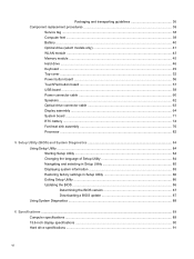
......43 Memory module ...45 Hard drive ...46 Keyboard ...49 Top cover ...52 Power button board ...56 TouchPad button board ...57 USB board ...59 Power connector cable ...60 Speakers ...62 Optical drive connector cable 63 Display assembly ...64 System board ...71 RTC battery ...74 Fan/heat sink assembly ...76 Processor ...82 5 Setup Utility (BIOS) and System Diagnostics 84 Using Setup Utility ...84 Starting Setup Utility ...84 Changing the language of Setup Utility 84 Navigating and selecting in Setup Utility 85 Displaying system information 85 Restoring factory settings in Setup Utility 86...
......43 Memory module ...45 Hard drive ...46 Keyboard ...49 Top cover ...52 Power button board ...56 TouchPad button board ...57 USB board ...59 Power connector cable ...60 Speakers ...62 Optical drive connector cable 63 Display assembly ...64 System board ...71 RTC battery ...74 Fan/heat sink assembly ...76 Processor ...82 5 Setup Utility (BIOS) and System Diagnostics 84 Using Setup Utility ...84 Starting Setup Utility ...84 Changing the language of Setup Utility 84 Navigating and selecting in Setup Utility 85 Displaying system information 85 Restoring factory settings in Setup Utility 86...
Maintenance and Service Guide
Page 11
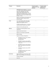
... brightness: 200 nits All display assemblies include 1 or 2 wireless local area network (WLAN) antenna cables Supports 16:9 ultra wide aspect ratio 2 customer-accessible/upgradable memory √ √ module slots Supports dual-channel memory √ √ Supports up to 8192 GB of system RAM √ √ DDR3/1333-MHz √ √ Supports the following configurations: √ √ ● 8192-MB total system memory (4096×2; Category Panel Memory Hard drives Description Computer models Computer models...
... brightness: 200 nits All display assemblies include 1 or 2 wireless local area network (WLAN) antenna cables Supports 16:9 ultra wide aspect ratio 2 customer-accessible/upgradable memory √ √ module slots Supports dual-channel memory √ √ Supports up to 8192 GB of system RAM √ √ DDR3/1333-MHz √ √ Supports the following configurations: √ √ ● 8192-MB total system memory (4096×2; Category Panel Memory Hard drives Description Computer models Computer models...

Maintenance and Service Guide
Page 20
... volume before putting on . ● Blinking white: The computer is in (microphone) jack Audio-out (headphone) jack Digital Media Slot Drive light Power light Description Connects an external VGA monitor or projector. It is normal for the internal fan to cycle on and off . 12 Chapter 2 External component identification WARNING! For additional safety information, refer to cool internal components. Left side Item (1) (2) (3) (4) (5) (6) (7) (8) (9) (10) Component External monitor port Vents (2) RJ-45 (network) jack HDMI port (select models only) USB port Audio...
... volume before putting on . ● Blinking white: The computer is in (microphone) jack Audio-out (headphone) jack Digital Media Slot Drive light Power light Description Connects an external VGA monitor or projector. It is normal for the internal fan to cycle on and off . 12 Chapter 2 External component identification WARNING! For additional safety information, refer to cool internal components. Left side Item (1) (2) (3) (4) (5) (6) (7) (8) (9) (10) Component External monitor port Vents (2) RJ-45 (network) jack HDMI port (select models only) USB port Audio...

Maintenance and Service Guide
Page 21
... designed to the computer. Right side 13 Right side Item (1) (2) (3) (4) (5) (6) Component Optical drive (select models only) Optical drive light USB ports (2) Power connector AC adapter light Security cable slot Description Reads and writes to external power and the battery is fully charged. ● Amber: A battery is charging. Connects an AC adapter. ● White: The computer is connected to an optical disc. ● On: The optical drive is in use. ● Off: The optical...
... designed to the computer. Right side 13 Right side Item (1) (2) (3) (4) (5) (6) Component Optical drive (select models only) Optical drive light USB ports (2) Power connector AC adapter light Security cable slot Description Reads and writes to external power and the battery is fully charged. ● Amber: A battery is charging. Connects an AC adapter. ● White: The computer is connected to an optical disc. ● On: The optical drive is in use. ● Off: The optical...
Maintenance and Service Guide
Page 27
... subsystem with UMA video memory (for more Plastics Kit spare part information. USB board (includes cable) 646128-001 Power connector cable 646121-001 Plastics Kit, includes: 646131-001 Hard drive compartment cover (includes one captive screw, secured by a C-clip) Memory module/wireless module compartment cover (includes one captive screw, secured by a C-clip) NOTE: See Plastics Kit on page 22 for use only with computer models in the United...
... subsystem with UMA video memory (for more Plastics Kit spare part information. USB board (includes cable) 646128-001 Power connector cable 646121-001 Plastics Kit, includes: 646131-001 Hard drive compartment cover (includes one captive screw, secured by a C-clip) Memory module/wireless module compartment cover (includes one captive screw, secured by a C-clip) NOTE: See Plastics Kit on page 22 for use only with computer models in the United...

Maintenance and Service Guide
Page 29
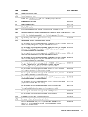
... Spare part number For use only with computer models equipped with an Intel Pentium processor and a 646181-001 graphics subsystem with UMA video memory For use only with computer models equipped with an Intel Celeron processor and a graphics subsystem with LightScribe 646126-001 DVD±RW and CD-RW Drive 659879-001 DVD-ROM Drive 659638-001 Optical drive slot space saver 659632-001 Hard drive (2.5-in...
... Spare part number For use only with computer models equipped with an Intel Pentium processor and a 646181-001 graphics subsystem with UMA video memory For use only with computer models equipped with an Intel Celeron processor and a graphics subsystem with LightScribe 646126-001 DVD±RW and CD-RW Drive 659879-001 DVD-ROM Drive 659638-001 Optical drive slot space saver 659632-001 Hard drive (2.5-in...

Maintenance and Service Guide
Page 51
... cable is connected to the system board. (The WLAN module tilts up.) Component replacement procedures 43 Remove the Phillips PM2.0×3.0 screw (2) that regulates wireless devices in Hibernation, turn the computer on page 40). 5. If you are unsure whether the computer is connected to the WLAN module #1 terminal. Remove the WLAN module: 1. Disconnect all external devices connected to restore device functionality, and then contact technical support. Remove the battery (see Optical drive (select models...
... cable is connected to the system board. (The WLAN module tilts up.) Component replacement procedures 43 Remove the Phillips PM2.0×3.0 screw (2) that regulates wireless devices in Hibernation, turn the computer on page 40). 5. If you are unsure whether the computer is connected to the WLAN module #1 terminal. Remove the WLAN module: 1. Disconnect all external devices connected to restore device functionality, and then contact technical support. Remove the battery (see Optical drive (select models...

Maintenance and Service Guide
Page 54
... computer. 4. Remove the hard drive: 1. Disconnect all external devices connected to the computer. 46 Chapter 4 Removal and replacement procedures Loosen the captive screw (1) that secures the hard drive compartment cover to the computer. 3. Remove the battery (see Optical drive (select models only) on page 41). Shut down through the operating system. 2. The hard drive connector cable is off or in the Cable Kit, spare part number 646119-001. Remove the memory module/wireless module compartment cover (see Battery on...
... computer. 4. Remove the hard drive: 1. Disconnect all external devices connected to the computer. 46 Chapter 4 Removal and replacement procedures Loosen the captive screw (1) that secures the hard drive compartment cover to the computer. 3. Remove the battery (see Optical drive (select models only) on page 41). Shut down through the operating system. 2. The hard drive connector cable is off or in the Cable Kit, spare part number 646119-001. Remove the memory module/wireless module compartment cover (see Battery on...

Maintenance and Service Guide
Page 57
...-AD1 646125-AB1 Before removing the keyboard, follow these steps: 1. Remove the memory module/wireless module compartment cover (see Hard drive on , and then shut it down the computer. Remove the hard drive compartment cover (see Optical drive (select models only) on page 40). 5. Disconnect all computer models: For use in Belgium 646125-A41 For use in Latin America For use in Bulgaria 646125-261 For use in the Netherlands For...
...-AD1 646125-AB1 Before removing the keyboard, follow these steps: 1. Remove the memory module/wireless module compartment cover (see Hard drive on , and then shut it down the computer. Remove the hard drive compartment cover (see Optical drive (select models only) on page 40). 5. Disconnect all computer models: For use in Belgium 646125-A41 For use in Latin America For use in Bulgaria 646125-261 For use in the Netherlands For...

Maintenance and Service Guide
Page 84
... located on page 71) 76 Chapter 4 Removal and replacement procedures Disconnect the power from the computer by high external temperatures, system power consumption, power management/battery conservation configurations, battery fast charging, and software requirements. Description For use only with computer models equipped with an AMD processor For use only with computer models equipped with an Intel Core i5 or i3 processor and a graphics subsystem with discrete video memory For use...
... located on page 71) 76 Chapter 4 Removal and replacement procedures Disconnect the power from the computer by high external temperatures, system power consumption, power management/battery conservation configurations, battery fast charging, and software requirements. Description For use only with computer models equipped with an AMD processor For use only with computer models equipped with an Intel Core i5 or i3 processor and a graphics subsystem with discrete video memory For use...
Maintenance and Service Guide
Page 91
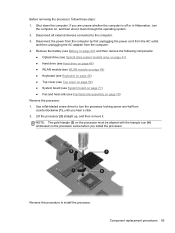
... battery (see Battery on page 40), and then remove the following components: ● Optical drive (see Optical drive (select models only) on page 41) ● Hard drive (see Hard drive on page 46) ● WLAN module (see WLAN module on page 43) ● Keyboard (see Keyboard on page 49) ● Top cover (see Top cover on page 52) ● System board (see System board on page 71) ● Fan...
... battery (see Battery on page 40), and then remove the following components: ● Optical drive (see Optical drive (select models only) on page 41) ● Hard drive (see Hard drive on page 46) ● WLAN module (see WLAN module on page 43) ● Keyboard (see Keyboard on page 49) ● Top cover (see Top cover on page 52) ● System board (see System board on page 71) ● Fan...
Maintenance and Service Guide
Page 92
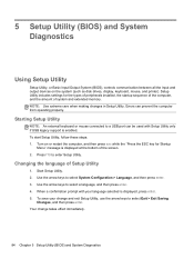
... output devices on or restart the computer, and then press esc while the "Press the ESC key for the types of peripherals installed, the startup sequence of the computer, and the amount of the screen. 2. Setup Utility includes settings for Startup Menu" message is enabled. Starting Setup Utility NOTE: An external keyboard or mouse connected to a USB port can prevent the computer from operating properly. Turn on the system (such as disk drives, display, keyboard, mouse, and printer). Changing...
... output devices on or restart the computer, and then press esc while the "Press the ESC key for the types of peripherals installed, the startup sequence of the computer, and the amount of the screen. 2. Setup Utility includes settings for Startup Menu" message is enabled. Starting Setup Utility NOTE: An external keyboard or mouse connected to a USB port can prevent the computer from operating properly. Turn on the system (such as disk drives, display, keyboard, mouse, and printer). Changing...

Maintenance and Service Guide
Page 94
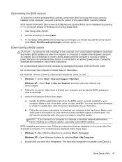
... Startup Menu" message is displayed at the factory, follow the on-screen instructions. - To return all settings in Setup Utility to the menu display. Follow the on the HP Web site. Use the arrow keys to enter Setup Utility. 3. Updating the BIOS Updated versions of the screen. 2. Press f10 to select Exit > Exit Saving Changes, and then press enter. or - Your changes go into effect when the computer restarts. Exiting Setup Utility ● To exit Setup Utility...
... Startup Menu" message is displayed at the factory, follow the on-screen instructions. - To return all settings in Setup Utility to the menu display. Follow the on the HP Web site. Use the arrow keys to enter Setup Utility. 3. Updating the BIOS Updated versions of the screen. 2. Press f10 to select Exit > Exit Saving Changes, and then press enter. or - Your changes go into effect when the computer restarts. Exiting Setup Utility ● To exit Setup Utility...
Maintenance and Service Guide
Page 95
... installed on -screen instructions to download your hard drive where the BIOS update is complete. Windows 7-Select Start > Help and Support > Maintain. Identify the BIOS update that are ready to select Exit > Exit Discarding Changes, and then press enter. Make a note of the date, name, or other identifier. To exit Setup Utility (BIOS) without saving your hard drive designation. Follow the on your selection to reliable external power using Setup Utility. 1. The hard drive designation is connected to the hard drive...
... installed on -screen instructions to download your hard drive where the BIOS update is complete. Windows 7-Select Start > Help and Support > Maintain. Identify the BIOS update that are ready to select Exit > Exit Discarding Changes, and then press enter. Make a note of the date, name, or other identifier. To exit Setup Utility (BIOS) without saving your hard drive designation. Follow the on your selection to reliable external power using Setup Utility. 1. The hard drive designation is connected to the hard drive...
Maintenance and Service Guide
Page 100
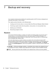
..., a Recovery drive is listed in the window. 7 Backup and recovery Your computer includes tools provided by the operating system and HP to help you safeguard your computer does not have been included if your information and restore it if ever needed. If for recovery discs or a recovery flash drive. CAUTION: HP Recovery Manager (partition, or discs/flash drive) restores only software that you can create using the HP Recovery partition (select models only), without the need a set of hard drive failure...
..., a Recovery drive is listed in the window. 7 Backup and recovery Your computer includes tools provided by the operating system and HP to help you safeguard your computer does not have been included if your information and restore it if ever needed. If for recovery discs or a recovery flash drive. CAUTION: HP Recovery Manager (partition, or discs/flash drive) restores only software that you can create using the HP Recovery partition (select models only), without the need a set of hard drive failure...

Maintenance and Service Guide
Page 101
... factory state if the hard drive fails, or if for the first time. Select Start > All Programs > Recovery Manager > Recovery Media Creation. 2. Creating restore media HP recommends that you create either a set of recovery discs or a recovery flash drive to be sure that you can restore your computer to continue the backup creation process. If you use an optional external optical drive (purchased separately) to AC power during this process. ● Only one set of recovery discs or a recovery flash drive: 1. Creating restore media...
... factory state if the hard drive fails, or if for the first time. Select Start > All Programs > Recovery Manager > Recovery Media Creation. 2. Creating restore media HP recommends that you create either a set of recovery discs or a recovery flash drive to be sure that you can restore your computer to continue the backup creation process. If you use an optional external optical drive (purchased separately) to AC power during this process. ● Only one set of recovery discs or a recovery flash drive: 1. Creating restore media...

Maintenance and Service Guide
Page 105
..., you to provide increased protection for tasks such as installing software, running utilities, or changing Windows settings. When to create restore points ● Before you add or modify software or hardware ● Periodically, whenever the computer is connected to AC power before you want to improve the security of your files and settings. To create a backup: 1. Depending on -screen instructions to a restore point and then change your information 97
..., you to provide increased protection for tasks such as installing software, running utilities, or changing Windows settings. When to create restore points ● Before you add or modify software or hardware ● Periodically, whenever the computer is connected to AC power before you want to improve the security of your files and settings. To create a backup: 1. Depending on -screen instructions to a restore point and then change your information 97

Maintenance and Service Guide
Page 115
... button components 8 buttons power 8 TouchPad 11 TouchPad on/off 11 C Cable Kit contents 22 spare part number 18, 22, 28 cables, service considerations 33 caps lock light 10 chipset, product description 2 components bottom 14 button 8 display 7 keys 9 left-side 12 lights 10 right-side 13 TouchPad 11 computer feet, locations 39 computer major components 17 computer part number 16, 38 computer specifications 89 connectors, service considerations 33 D Digital Media Slot 12 display assembly removal 64 spare part numbers...
... button components 8 buttons power 8 TouchPad 11 TouchPad on/off 11 C Cable Kit contents 22 spare part number 18, 22, 28 cables, service considerations 33 caps lock light 10 chipset, product description 2 components bottom 14 button 8 display 7 keys 9 left-side 12 lights 10 right-side 13 TouchPad 11 computer feet, locations 39 computer major components 17 computer part number 16, 38 computer specifications 89 connectors, service considerations 33 D Digital Media Slot 12 display assembly removal 64 spare part numbers...
Maintenance and Service Guide
Page 116
... 12 light components 10 lights AC adapter 13 caps lock 10 drive 12 optical drive 13 power 10, 12 TouchPad 10, 11 webcam 7 wireless 10 M mass storage device precautions 34 removal 46 spare part numbers 24, 46 memory module product description 3 removal 45 spare part numbers 21, 28, 45 memory module compartment 14 memory module/wireless module compartment cover illustrated 26 removal 41 microphone location 7 product description 4 microphone jack 12 microphone module removal 66 spare part number 23, 28, 66 model description 16, 39 model name 1 monitor port 12 N network jack 12 O operating...
... 12 light components 10 lights AC adapter 13 caps lock 10 drive 12 optical drive 13 power 10, 12 TouchPad 10, 11 webcam 7 wireless 10 M mass storage device precautions 34 removal 46 spare part numbers 24, 46 memory module product description 3 removal 45 spare part numbers 21, 28, 45 memory module compartment 14 memory module/wireless module compartment cover illustrated 26 removal 41 microphone location 7 product description 4 microphone jack 12 microphone module removal 66 spare part number 23, 28, 66 model description 16, 39 model name 1 monitor port 12 N network jack 12 O operating...
Maintenance and Service Guide
Page 117
...audio 4 chipset 2 display panel 3 Ethernet 4 external media cards 5 graphics 2 hard drives 3 keyboard 5 memory module 3 microphone 4 operating system 6 optical drive 4 pointing device 5 ports 5 power requirements 6 processors 1 product name 1 security 6 serviceability 6 video 4 wireless 4 product name 1, 15, 38 product number 16, 38 R removal/replacement preliminaries 33 procedures 38 right-side components 13 RJ-45 jack 12 RTC battery removal 74 spare part number 19, 30, 74 S Screw Kit, spare part number 25, 30 security cable slot 13 security, product description 6 serial number 15, 38 service...
...audio 4 chipset 2 display panel 3 Ethernet 4 external media cards 5 graphics 2 hard drives 3 keyboard 5 memory module 3 microphone 4 operating system 6 optical drive 4 pointing device 5 ports 5 power requirements 6 processors 1 product name 1 security 6 serviceability 6 video 4 wireless 4 product name 1, 15, 38 product number 16, 38 R removal/replacement preliminaries 33 procedures 38 right-side components 13 RJ-45 jack 12 RTC battery removal 74 spare part number 19, 30, 74 S Screw Kit, spare part number 25, 30 security cable slot 13 security, product description 6 serial number 15, 38 service...


