Maintenance and Service Guide
Page 6
Packaging and transporting guidelines 32 Component replacement procedures 34 Service tag ...34 Computer feet ...35 Battery ...36 Optical drive (select models only 37 WLAN module ...40 Memory module ...42 Hard drive ...43 Keyboard ...46 Top cover ...49 Power button ...TouchPad button board 54 USB board ...56 Power connector cable 57 Speakers ...59 Optical drive connector cable 60 Display assembly ...61 System board ...68 RTC battery ...71 Fan/heat sink assembly 73 Processor ...79 5 Setup Utility (BIOS) and System Diagnostics 81 Using Setup Utility ...81 Starting Setup Utility 81 Changing...
Packaging and transporting guidelines 32 Component replacement procedures 34 Service tag ...34 Computer feet ...35 Battery ...36 Optical drive (select models only 37 WLAN module ...40 Memory module ...42 Hard drive ...43 Keyboard ...46 Top cover ...49 Power button ...TouchPad button board 54 USB board ...56 Power connector cable 57 Speakers ...59 Optical drive connector cable 60 Display assembly ...61 System board ...68 RTC battery ...71 Fan/heat sink assembly 73 Processor ...79 5 Setup Utility (BIOS) and System Diagnostics 81 Using Setup Utility ...81 Starting Setup Utility 81 Changing...
Maintenance and Service Guide
Page 7
... to a previous date and time 95 8 Power cord set requirements 96 Requirements for all countries 96 Requirements for specific countries and regions 97 9 Recycling ...98 Battery ...98 Display ...98 Index ...104 vii
... to a previous date and time 95 8 Power cord set requirements 96 Requirements for all countries 96 Requirements for specific countries and regions 97 9 Recycling ...98 Battery ...98 Display ...98 Index ...104 vii
Maintenance and Service Guide
Page 13
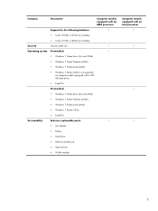
... (64-bit) ● Windows 7 Starter 32-bit ● FreeDOS Serviceability End-user replaceable parts: √ ● AC adapter ● Battery ● Hard drive ● Memory modules (2) ● Optical drive ● WLAN module Computer models equipped with a 320GB hard drive) ●... Description Computer models equipped with an AMD processor Support for the following batteries: √ ● 6-cell, 55-Whr, 2.55-Ah Li-ion battery ● 6-cell, 47-Whr, 2.20-Ah Li-ion battery Security Security cable slot √ Operating system Preinstalled: √ ●...
... (64-bit) ● Windows 7 Starter 32-bit ● FreeDOS Serviceability End-user replaceable parts: √ ● AC adapter ● Battery ● Hard drive ● Memory modules (2) ● Optical drive ● WLAN module Computer models equipped with a 320GB hard drive) ●... Description Computer models equipped with an AMD processor Support for the following batteries: √ ● 6-cell, 55-Whr, 2.55-Ah Li-ion battery ● 6-cell, 47-Whr, 2.20-Ah Li-ion battery Security Security cable slot √ Operating system Preinstalled: √ ●...
Maintenance and Service Guide
Page 20
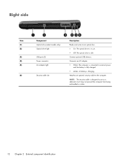
...: The optical drive is idle. Connects an AC adapter. ● White: The computer is charging. Attaches an optional security cable to external power and the battery is fully charged. ● Amber: A battery is connected to the computer.
...: The optical drive is idle. Connects an AC adapter. ● White: The computer is charging. Attaches an optional security cable to external power and the battery is fully charged. ● Amber: A battery is connected to the computer.
Maintenance and Service Guide
Page 21
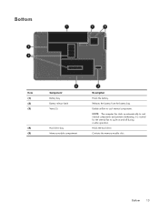
Holds the hard drive. It is normal for the internal fan to cool internal components. Contains the memory module slots. Bottom 13 Releases the battery from the battery bay. Enable airflow to cycle on and off during routine operation. NOTE: The computer fan starts up automatically to cool internal components and prevent overheating. Bottom Item (1) (2) (3) (4) (5) Component Battery bay Battery release latch Vents (5) Hard drive bay Memory module compartment Description Holds the battery.
Holds the hard drive. It is normal for the internal fan to cool internal components. Contains the memory module slots. Bottom 13 Releases the battery from the battery bay. Enable airflow to cycle on and off during routine operation. NOTE: The computer fan starts up automatically to cool internal components and prevent overheating. Bottom Item (1) (2) (3) (4) (5) Component Battery bay Battery release latch Vents (5) Hard drive bay Memory module compartment Description Holds the battery.
Maintenance and Service Guide
Page 26
... only with computer models equipped with an AMD processor 650277-001 For use only with computer models equipped with an Intel processor 646135-001 RTC battery (includes cable and double-sided tape) 646132-001 Processor (includes replacement thermal material): Intel Pentium P6300 2.26-GHz processor (3.0-MB L3 cache, dual core, 35...
... only with computer models equipped with an AMD processor 650277-001 For use only with computer models equipped with an Intel processor 646135-001 RTC battery (includes cable and double-sided tape) 646132-001 Processor (includes replacement thermal material): Intel Pentium P6300 2.26-GHz processor (3.0-MB L3 cache, dual core, 35...

Maintenance and Service Guide
Page 27
... a graphics subsystem with UMA video memory 646184-001 Base enclosure (includes battery release latch, heat sink, replacement thermal material, and 4 rubber feet) 646114-001 Battery: 6-cell, 55-Whr, 2.55-Ah Li-ion battery 593554-001 6-cell, 47-Whr, 2.20-Ah Li-ion battery 593553-001 DVD±RW and CD-RW Super Multi Double...
... a graphics subsystem with UMA video memory 646184-001 Base enclosure (includes battery release latch, heat sink, replacement thermal material, and 4 rubber feet) 646114-001 Battery: 6-cell, 55-Whr, 2.55-Ah Li-ion battery 593554-001 6-cell, 47-Whr, 2.20-Ah Li-ion battery 593553-001 DVD±RW and CD-RW Super Multi Double...
Maintenance and Service Guide
Page 33
....11b/g/n 1x1 WiFi and Bluetooth 2.1+EDR Combo Adapter (BT3.0+HS ready) 593553-001 6-cell, 47-Whr, 2.20-Ah Li-ion battery 593554-001 6-cell, 55-Whr, 2.55-Ah Li-ion battery 602993-001 Realtek 8188BC8 802.11a/b/g/n 2x2 WiFi and Bluetooth 3.0+HS Combo Adapter 609939-001 65-W RC V HP Smart AC adapter...
....11b/g/n 1x1 WiFi and Bluetooth 2.1+EDR Combo Adapter (BT3.0+HS ready) 593553-001 6-cell, 47-Whr, 2.20-Ah Li-ion battery 593554-001 6-cell, 55-Whr, 2.55-Ah Li-ion battery 602993-001 Realtek 8188BC8 802.11a/b/g/n 2x2 WiFi and Bluetooth 3.0+HS Combo Adapter 609939-001 65-W RC V HP Smart AC adapter...

Maintenance and Service Guide
Page 34
...-001 Microphone module 646111-001 Antenna Kit (includes left and right wireless antenna cables and transceivers) 646113-001 Display enclosure 646114-001 Base enclosure (includes battery release latch, heat sink, replacement thermal material, and 4 rubber feet) 646117-001 Display bezel for use with computer models equipped with a webcam and a microphone 646118...
...-001 Microphone module 646111-001 Antenna Kit (includes left and right wireless antenna cables and transceivers) 646113-001 Display enclosure 646114-001 Base enclosure (includes battery release latch, heat sink, replacement thermal material, and 4 rubber feet) 646117-001 Display bezel for use with computer models equipped with a webcam and a microphone 646118...

Maintenance and Service Guide
Page 36
Spare part number Description 646132-001 RTC battery (includes cable and double-sided tape) 646133-001 Screw Kit 646134-001 Display Screw Kit (includes Mylar screw covers and screws) 646135-001 Thermal Material ...
Spare part number Description 646132-001 RTC battery (includes cable and double-sided tape) 646133-001 Screw Kit 646134-001 Display Screw Kit (includes Mylar screw covers and screws) 646135-001 Thermal Material ...

Maintenance and Service Guide
Page 44
...off or in Hibernation, turn the computer on, and then shut it down the computer. Disconnect all external devices connected to release the battery. 2. Disconnect the power from the computer by first unplugging the power cord from the AC outlet and then unplugging the AC adapter ...from the computer. 36 Chapter 4 Removal and replacement procedures Slide the battery release latch (1) to the computer. 3. Shut down through the operating system. 2. Remove the battery: 1. Pivot the front edge of the battery (2) up and back. 3. Remove the...
...off or in Hibernation, turn the computer on, and then shut it down the computer. Disconnect all external devices connected to release the battery. 2. Disconnect the power from the computer by first unplugging the power cord from the AC outlet and then unplugging the AC adapter ...from the computer. 36 Chapter 4 Removal and replacement procedures Slide the battery release latch (1) to the computer. 3. Shut down through the operating system. 2. Remove the battery: 1. Pivot the front edge of the battery (2) up and back. 3. Remove the...
Maintenance and Service Guide
Page 45
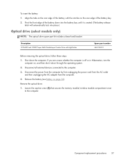
... with the notches on , and then shut it is off or in Hibernation, turn the computer on the rear edge of the battery with LightScribe Spare part number 646126-001 Before removing the optical drive, follow these steps: 1. Loosen the captive screw (1) that secures...computer. 4. Pivot the front edge of the battery down the computer. Remove the battery (see Battery on the rear edge of the battery bay. 2. If you are unsure whether the computer is seated. (The battery release latch will automatically lock into the battery bay until it down through the operating system...
... with the notches on , and then shut it is off or in Hibernation, turn the computer on the rear edge of the battery with LightScribe Spare part number 646126-001 Before removing the optical drive, follow these steps: 1. Loosen the captive screw (1) that secures...computer. 4. Pivot the front edge of the battery down the computer. Remove the battery (see Battery on the rear edge of the battery bay. 2. If you are unsure whether the computer is seated. (The battery release latch will automatically lock into the battery bay until it down through the operating system...

Maintenance and Service Guide
Page 48
...message, remove the module to restore device functionality, and then contact technical support. Remove the memory module/wireless module compartment cover (see Battery on the WLAN module. Remove the WLAN module: 1. NOTE: The #1 WLAN antenna cable is connected to the system board. (The... module, follow these steps: 1. Remove the Phillips PM2.0×3.0 screw (2) that regulates wireless devices in your country or region. Remove the battery (see Optical drive (select models only) on , and then shut it down the computer. Disconnect the WLAN antenna cables (1) from the ...
...message, remove the module to restore device functionality, and then contact technical support. Remove the memory module/wireless module compartment cover (see Battery on the WLAN module. Remove the WLAN module: 1. NOTE: The #1 WLAN antenna cable is connected to the system board. (The... module, follow these steps: 1. Remove the Phillips PM2.0×3.0 screw (2) that regulates wireless devices in your country or region. Remove the battery (see Optical drive (select models only) on , and then shut it down the computer. Disconnect the WLAN antenna cables (1) from the ...
Maintenance and Service Guide
Page 50
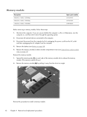
...the retaining tabs (1) on page 37). Shut down through the operating system. 2. Disconnect all external devices connected to the computer. 3. Remove the battery (see Optical drive (select models only) on each side of the memory module slot to install a memory module. 42 Chapter 4 Removal and ...replacement procedures Remove the memory module/wireless module compartment cover (see Battery on , and then shut it away from the computer. 4. If you are unsure whether the computer is off or in Hibernation, turn...
...the retaining tabs (1) on page 37). Shut down through the operating system. 2. Disconnect all external devices connected to the computer. 3. Remove the battery (see Optical drive (select models only) on each side of the memory module slot to install a memory module. 42 Chapter 4 Removal and ...replacement procedures Remove the memory module/wireless module compartment cover (see Battery on , and then shut it away from the computer. 4. If you are unsure whether the computer is off or in Hibernation, turn...
Maintenance and Service Guide
Page 51
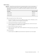
... the power cord from the AC outlet and then unplugging the AC adapter from the computer. 4. Remove the memory module/wireless module compartment cover (see Battery on page 36). 5. Remove the hard drive: 1. Hard drive NOTE: The hard drive spare part kit does not include the hard drive connector cable...hard drive compartment cover to the computer. 3. The hard drive connector cable is off or in Hibernation, turn the computer on page 37). Remove the battery (see Optical drive (select models only) on , and then shut it down the computer. If you are included in the Cable Kit, spare ...
... the power cord from the AC outlet and then unplugging the AC adapter from the computer. 4. Remove the memory module/wireless module compartment cover (see Battery on page 36). 5. Remove the hard drive: 1. Hard drive NOTE: The hard drive spare part kit does not include the hard drive connector cable...hard drive compartment cover to the computer. 3. The hard drive connector cable is off or in Hibernation, turn the computer on page 37). Remove the battery (see Optical drive (select models only) on , and then shut it down the computer. If you are included in the Cable Kit, spare ...
Maintenance and Service Guide
Page 54
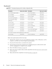
... the AC adapter from the computer. 4. Keyboard NOTE: The keyboard spare part kit includes a keyboard cable. Shut down through the operating system. 2. Remove the battery (see Battery on page 43). 46 Chapter 4 Removal and replacement procedures Disconnect all computer models: For use in Latin America For use in Belgium 646125-A41 For...
... the AC adapter from the computer. 4. Keyboard NOTE: The keyboard spare part kit includes a keyboard cable. Shut down through the operating system. 2. Remove the battery (see Battery on page 43). 46 Chapter 4 Removal and replacement procedures Disconnect all computer models: For use in Latin America For use in Belgium 646125-A41 For...
Maintenance and Service Guide
Page 57
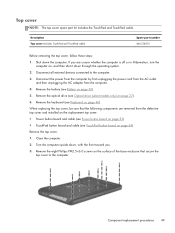
... operating system. 2. Component replacement procedures 49 If you . 3. Remove the keyboard (see Optical drive (select models only) on page 46). Remove the battery (see TouchPad button board on page 36). 5. Turn the computer upside down the computer. When replacing the top cover, be sure that the following components... top cover: ● Power button board and cable (see Power button board on page 53) ● TouchPad button board and cable (see Battery on page 54) Remove the top cover: 1. Top cover NOTE: The top cover spare part kit includes the TouchPad and TouchPad cable.
... operating system. 2. Component replacement procedures 49 If you . 3. Remove the keyboard (see Optical drive (select models only) on page 46). Remove the battery (see TouchPad button board on page 36). 5. Turn the computer upside down the computer. When replacing the top cover, be sure that the following components... top cover: ● Power button board and cable (see Power button board on page 53) ● TouchPad button board and cable (see Battery on page 54) Remove the top cover: 1. Top cover NOTE: The top cover spare part kit includes the TouchPad and TouchPad cable.
Maintenance and Service Guide
Page 58
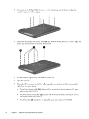
Open the computer. 8. Remove the two Phillips PM2.5×9.0 screws (1) and the three Phillips PM2.0×3.0 screws (2) in the battery bay that secure the top cover to the computer. 5. Release the ZIF connectors to the computer. 6. Turn the computer right-side up, with the TouchPad... button board spare part kit, spare part number 646130-001) ● TouchPad cable (3) (included in the battery bay and the hard drive bay that secure the top cover to which the following cables are attached, and then disconnect the cables from the...
Open the computer. 8. Remove the two Phillips PM2.5×9.0 screws (1) and the three Phillips PM2.0×3.0 screws (2) in the battery bay that secure the top cover to the computer. 5. Release the ZIF connectors to the computer. 6. Turn the computer right-side up, with the TouchPad... button board spare part kit, spare part number 646130-001) ● TouchPad cable (3) (included in the battery bay and the hard drive bay that secure the top cover to which the following cables are attached, and then disconnect the cables from the...
Maintenance and Service Guide
Page 61
... power from the computer by first unplugging the power cord from the AC outlet and then unplugging the AC adapter from the computer. 4. Remove the battery (see Battery on page 36), and then remove the following components: ● Optical drive (see Optical drive (select models only) on page 37) ● Keyboard (see...
... power from the computer by first unplugging the power cord from the AC outlet and then unplugging the AC adapter from the computer. 4. Remove the battery (see Battery on page 36), and then remove the following components: ● Optical drive (see Optical drive (select models only) on page 37) ● Keyboard (see...
Maintenance and Service Guide
Page 62
Shut down , with double-sided tape.) 3. If you are attached to the top cover with the top toward you. 2. Remove the battery (see Battery on page 36), and then remove the following components: ● Optical drive (see Optical drive (select models only) on page 37) ● Keyboard (see Keyboard ...
Shut down , with double-sided tape.) 3. If you are attached to the top cover with the top toward you. 2. Remove the battery (see Battery on page 36), and then remove the following components: ● Optical drive (see Optical drive (select models only) on page 37) ● Keyboard (see Keyboard ...

