Hardware Guide
Page 1
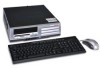
b Hardware Reference Guide Small Form Factor Models Compaq Evo Desktop Family Document Part Number: 243849-003 May 2002 This book provides basic information for upgrading this series of computers.
b Hardware Reference Guide Small Form Factor Models Compaq Evo Desktop Family Document Part Number: 243849-003 May 2002 This book provides basic information for upgrading this series of computers.
Hardware Guide
Page 3
... Access Keyboard Components 1-4 Customizing the Easy Access Buttons 1-5 Using the Windows Logo Key 1-6 Special Mouse Functions 1-6 Serial Number Location 1-7 2 Hardware Upgrades Installation Sequence 2-1 Drawer Installation Method 2-2 Smart Cover Lock 2-3 Using the Smart Cover FailSafe Key 2-3 Removing the Computer Cover 2-5 Installing Additional Memory ... Card 2-12 Removing the AGP Card 2-15 Drive Positions 2-17 Installing Additional Drives 2-18 Upgrading the Hard Drive 2-18 Removing an Optical Drive 2-20 Installing an Optional Optical Drive 2-22 Hardware Reference Guide iii
... Access Keyboard Components 1-4 Customizing the Easy Access Buttons 1-5 Using the Windows Logo Key 1-6 Special Mouse Functions 1-6 Serial Number Location 1-7 2 Hardware Upgrades Installation Sequence 2-1 Drawer Installation Method 2-2 Smart Cover Lock 2-3 Using the Smart Cover FailSafe Key 2-3 Removing the Computer Cover 2-5 Installing Additional Memory ... Card 2-12 Removing the AGP Card 2-15 Drive Positions 2-17 Installing Additional Drives 2-18 Upgrading the Hard Drive 2-18 Removing an Optical Drive 2-20 Installing an Optional Optical Drive 2-22 Hardware Reference Guide iii
Hardware Guide
Page 13
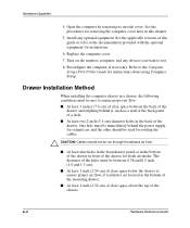
... Reference Guide 2-1 If the computer is very important that you follow this sequence of steps to ensure the proper installation of any optional equipment. 2 Hardware Upgrades Installation Sequence It is already on, turn it off and disconnect the power cord from the wall outlet. Å WARNING: To reduce the risk of...
... Reference Guide 2-1 If the computer is very important that you follow this sequence of steps to ensure the proper installation of any optional equipment. 2 Hardware Upgrades Installation Sequence It is already on, turn it off and disconnect the power cord from the wall outlet. Å WARNING: To reduce the risk of...
Hardware Guide
Page 14
... and 0.5 inch (1.0 and 1.3 cm). Install any devices you want to the Computer Setup (F10) Utility Guide for fresh air intake. Replace the computer cover. 7. Hardware Upgrades 4. See the procedures for instructions. 6. The diameter of a desk.
... and 0.5 inch (1.0 and 1.3 cm). Install any devices you want to the Computer Setup (F10) Utility Guide for fresh air intake. Replace the computer cover. 7. Hardware Upgrades 4. See the procedures for instructions. 6. The diameter of a desk.
Hardware Guide
Page 15
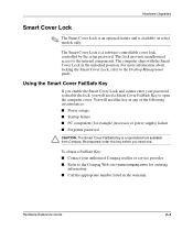
Be prepared; Hardware Upgrades Smart Cover Lock ✎ The Smart Cover Lock is an ...computer ships with the Smart Cover Lock in any of the following circumstances: I Power outage I Startup failure I PC component (for ordering information. For more information about locking the Smart Cover Lock, refer to the internal components. ...Key is a specialized tool available from Compaq. This lock prevents unauthorized access to the Desktop Management guide. order this key before you will need a Smart Cover FailSafe Key to the Compaq Web site (www.compaq.com) for example, processor or power...
Be prepared; Hardware Upgrades Smart Cover Lock ✎ The Smart Cover Lock is an ...computer ships with the Smart Cover Lock in any of the following circumstances: I Power outage I Startup failure I PC component (for ordering information. For more information about locking the Smart Cover Lock, refer to the internal components. ...Key is a specialized tool available from Compaq. This lock prevents unauthorized access to the Desktop Management guide. order this key before you will need a Smart Cover FailSafe Key to the Compaq Web site (www.compaq.com) for example, processor or power...
Hardware Guide
Page 16
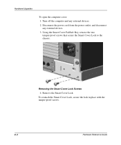
Turn off the computer and any external devices. 3. Removing the Smart Cover Lock Screws 4. To reattach the Smart Cover Lock, secure the lock in place with the tamper-proof screws. 2-4 Hardware Reference Guide Disconnect the power cord from the power outlet, and disconnect any external devices. 2. Using the Smart Cover FailSafe Key, remove the two tamper-proof screws that secure the Smart Cover Lock to the chassis. Remove the Smart Cover Lock. Hardware Upgrades To open the computer cover: 1.
Turn off the computer and any external devices. 3. Removing the Smart Cover Lock Screws 4. To reattach the Smart Cover Lock, secure the lock in place with the tamper-proof screws. 2-4 Hardware Reference Guide Disconnect the power cord from the power outlet, and disconnect any external devices. 2. Using the Smart Cover FailSafe Key, remove the two tamper-proof screws that secure the Smart Cover Lock to the chassis. Remove the Smart Cover Lock. Hardware Upgrades To open the computer cover: 1.
Hardware Guide
Page 17
... cover latches located on the sides of the computer allow easy removal of the computer cover without the use Computer Setup to unlock it. 2. Hardware Upgrades Removing the Computer Cover To install optional equipment, you have locked the Smart Cover Lock, refer to the previous section on Smart Cover Lock or...
... cover latches located on the sides of the computer allow easy removal of the computer cover without the use Computer Setup to unlock it. 2. Hardware Upgrades Removing the Computer Cover To install optional equipment, you have locked the Smart Cover Lock, refer to the previous section on Smart Cover Lock or...
Hardware Guide
Page 18
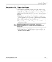
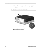
Hardware Upgrades 5. Removing the Computer Cover 2-6 Hardware Reference Guide As you slide the computer cover forward, release the buttons and allow them to return to the original position, then lift the cover up and off the unit. ✎ To replace the cover, reverse this procedure.
Hardware Upgrades 5. Removing the Computer Cover 2-6 Hardware Reference Guide As you slide the computer cover forward, release the buttons and allow them to return to the original position, then lift the cover up and off the unit. ✎ To replace the cover, reverse this procedure.
Hardware Guide
Page 19
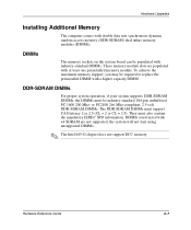
...or CL = 2.5). or PC2100 266 Mhz-compliant, 2.5 volt DDR-SDRAM DIMMs. The DDR-SDRAM DIMMs must be industry-standard 184-pin, unbuffered PC 1600 200 Mhz- the system will not start using unsupported DIMMs. ✎ The Intel 845-G chipset does not support ECC memory. DIMMs The memory...replace the preinstalled DIMM with double data rate synchronous dynamic random access memory (DDR-SDRAM) dual inline memory modules (DIMMs). Hardware Upgrades Installing Additional Memory The computer comes with a higher capacity DIMM. To achieve the maximum memory support, you may be populated with...
...or CL = 2.5). or PC2100 266 Mhz-compliant, 2.5 volt DDR-SDRAM DIMMs. The DDR-SDRAM DIMMs must be industry-standard 184-pin, unbuffered PC 1600 200 Mhz- the system will not start using unsupported DIMMs. ✎ The Intel 845-G chipset does not support ECC memory. DIMMs The memory...replace the preinstalled DIMM with double data rate synchronous dynamic random access memory (DDR-SDRAM) dual inline memory modules (DIMMs). Hardware Upgrades Installing Additional Memory The computer comes with a higher capacity DIMM. To achieve the maximum memory support, you may be populated with...
Hardware Guide
Page 20
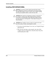
... oxidation resulting from the power outlet. 2-8 Hardware Reference Guide Before beginning these procedures, ensure that you have gold metal contacts. When upgrading your memory, it is important to use Computer Setup to unlock the lock. 2. Shut down the operating system properly, then turn ...contacts. Doing so may damage the module. 1. If you are discharged of static electricity by briefly touching a grounded metal object. Hardware Upgrades Installing DDR-SDRAM DIMMs Ä CAUTION: Your memory module sockets have locked the Smart Cover Lock, use memory modules with gold metal...
... oxidation resulting from the power outlet. 2-8 Hardware Reference Guide Before beginning these procedures, ensure that you have gold metal contacts. When upgrading your memory, it is important to use Computer Setup to unlock the lock. 2. Shut down the operating system properly, then turn ...contacts. Doing so may damage the module. 1. If you are discharged of static electricity by briefly touching a grounded metal object. Hardware Upgrades Installing DDR-SDRAM DIMMs Ä CAUTION: Your memory module sockets have locked the Smart Cover Lock, use memory modules with gold metal...
Hardware Guide
Page 21
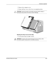
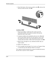
Hardware Upgrades 3. Rotating the Easy Access Drive Bay 5. Hardware Reference Guide 2-9 Rotate the Easy Access drive bay to an upright position. Ä CAUTION: Check the position of personal injury from hot surfaces, allow the internal system components to prevent damage. Locate the memory module sockets. Å WARNING: To reduce risk of all cables and wires before raising or lowering the easy access drive bay to cool before touching. Remove the computer cover. 4.
Hardware Upgrades 3. Rotating the Easy Access Drive Bay 5. Hardware Reference Guide 2-9 Rotate the Easy Access drive bay to an upright position. Ä CAUTION: Check the position of personal injury from hot surfaces, allow the internal system components to prevent damage. Locate the memory module sockets. Å WARNING: To reduce risk of all cables and wires before raising or lowering the easy access drive bay to cool before touching. Remove the computer cover. 4.
Hardware Guide
Page 22
Hardware Upgrades 6. Open both latches of the sockets. 8. Installing a DIMM 7. A memory module can be installed in only one way. Replace the computer cover. 11. Repeat steps 6 through 8 ...
Hardware Upgrades 6. Open both latches of the sockets. 8. Installing a DIMM 7. A memory module can be installed in only one way. Replace the computer cover. 11. Repeat steps 6 through 8 ...
Hardware Guide
Page 23
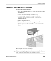
... the tab on the brace latches into the slot on the side of the power supply. Disconnect all cables attached to unlock the lock. 2. Hardware Upgrades Removing the Expansion Card Cage To remove the expansion card cage: 1. Pull the expansion card cage straight up to the expansion card cage. 4.
... the tab on the brace latches into the slot on the side of the power supply. Disconnect all cables attached to unlock the lock. 2. Hardware Upgrades Removing the Expansion Card Cage To remove the expansion card cage: 1. Pull the expansion card cage straight up to the expansion card cage. 4.
Hardware Guide
Page 24
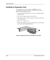
... outlet, then disconnect any external devices. 3. If you want to 6.875 inches (17.46 cm) in the Expansion Card Cage 2-12 Hardware Reference Guide Hardware Upgrades Installing an Expansion Card Your computer has two PCI expansion slots 1. To install an expansion card: 1. Each slot can accommodate an expansion card up to...
... outlet, then disconnect any external devices. 3. If you want to 6.875 inches (17.46 cm) in the Expansion Card Cage 2-12 Hardware Reference Guide Hardware Upgrades Installing an Expansion Card Your computer has two PCI expansion slots 1. To install an expansion card: 1. Each slot can accommodate an expansion card up to...
Hardware Guide
Page 25
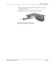
Remove the slot cover from the expansion card cage. Removing the Expansion Slot Cover Hardware Reference Guide 2-13 Hardware Upgrades 6. Remove the retaining screws that secure the slot cover to the expansion card cage. 7.
Remove the slot cover from the expansion card cage. Removing the Expansion Slot Cover Hardware Reference Guide 2-13 Hardware Upgrades 6. Remove the retaining screws that secure the slot cover to the expansion card cage. 7.
Hardware Guide
Page 26
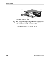
Reinstall the retaining screws to line it up with the corner bracket and press firmly on the card so that the whole connector seats properly in the expansion card slot. 9. Installing an Expansion Card ✎ When you install an expansion card, make sure to secure the card. 2-14 Hardware Reference Guide Hardware Upgrades 8. Install the expansion card.
Reinstall the retaining screws to line it up with the corner bracket and press firmly on the card so that the whole connector seats properly in the expansion card slot. 9. Installing an Expansion Card ✎ When you install an expansion card, make sure to secure the card. 2-14 Hardware Reference Guide Hardware Upgrades 8. Install the expansion card.
Hardware Guide
Page 27
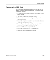
... any external devices. 4. Remove the expansion card cage (refer to unlock the lock. 2. Hardware Reference Guide 2-15 Remove the screw from the AGP slot: 1. Hardware Upgrades Removing the AGP Card A 1.5V low profile Accelerated Graphics Port (AGP) card may be installed in the AGP slot on "Removing the Expansion Card Cage"). 6.
... any external devices. 4. Remove the expansion card cage (refer to unlock the lock. 2. Hardware Reference Guide 2-15 Remove the screw from the AGP slot: 1. Hardware Upgrades Removing the AGP Card A 1.5V low profile Accelerated Graphics Port (AGP) card may be installed in the AGP slot on "Removing the Expansion Card Cage"). 6.
Hardware Guide
Page 28
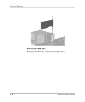
Hardware Upgrades Removing the AGP Card To replace the AGP card, reverse the above procedures. 2-16 Hardware Reference Guide
Hardware Upgrades Removing the AGP Card To replace the AGP card, reverse the above procedures. 2-16 Hardware Reference Guide
Hardware Guide
Page 29
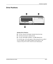
Hardware Reference Guide 2-17 Drive Positions Hardware Upgrades Desktop Drive Positions 1 3.5-inch, internal, third-height, standard hard drive bay 2 5.25-inch drive bay for more information. Refer to the Computer Setup (F10) Utility Guide for optional drives 3 3.5-inch, third-height, standard, 1.44-MB diskette drive To verify the type, size, and capacity of the storage devices installed in your computer, run Compaq Computer Setup.
Hardware Reference Guide 2-17 Drive Positions Hardware Upgrades Desktop Drive Positions 1 3.5-inch, internal, third-height, standard hard drive bay 2 5.25-inch drive bay for more information. Refer to the Computer Setup (F10) Utility Guide for optional drives 3 3.5-inch, third-height, standard, 1.44-MB diskette drive To verify the type, size, and capacity of the storage devices installed in your computer, run Compaq Computer Setup.
Hardware Guide
Page 30
...The 3.5-inch hard drive is on the right side of static electricity. The first external bay contains a preinstalled diskette drive. The Compaq supplied metric screws are inserting or removing a hard drive, shut down the operating system properly, then turn off the computer and...external devices. 3. I If you are black. Ä CAUTION: To prevent loss of the computer chassis, behind the front bezel. Hardware Upgrades Installing Additional Drives The computer has two external drive bays. When installing additional drives, follow these guidelines: I Avoid exposing a hard drive ...
...The 3.5-inch hard drive is on the right side of static electricity. The first external bay contains a preinstalled diskette drive. The Compaq supplied metric screws are inserting or removing a hard drive, shut down the operating system properly, then turn off the computer and...external devices. 3. I If you are black. Ä CAUTION: To prevent loss of the computer chassis, behind the front bezel. Hardware Upgrades Installing Additional Drives The computer has two external drive bays. When installing additional drives, follow these guidelines: I Avoid exposing a hard drive ...


