Service Manual
Page 2
...inch) Height : 426.0 mm (16.77 inch) 7. Scanning Frequency Horizontal Vertical : 30 ~ 70 kHz : 50 ~ 140 Hz 3. POWER SUPPLY 3-1. Signal Connector 3 row 15-pin Connector (Attached) 2-4. DISPLAY AREA 4-1. CONTENTS SPECIFICATIONS 2 SAFETY PRECAUTIONS 3 TIMING CHART 4 OPERATING INSTRUCTIONS 5 WIRING DIAGRAM 6 BLOCK DIAGRAM 7 DESCRIPTION OF BLOCK DIAGRAM 8 ADJUSTMENT 10 TROUBLESHOOTING GUIDE 12 EXPLODED VIEW 22 REPLACEMENT PARTS LIST 24 PIN CONFIGURATION 29 PACKING AND ACCESSORIES 31 SCHEMATIC DIAGRAM 32 PRINTED CIRCUIT BOARD 34 SPECIFICATIONS 1. Video...
...inch) Height : 426.0 mm (16.77 inch) 7. Scanning Frequency Horizontal Vertical : 30 ~ 70 kHz : 50 ~ 140 Hz 3. POWER SUPPLY 3-1. Signal Connector 3 row 15-pin Connector (Attached) 2-4. DISPLAY AREA 4-1. CONTENTS SPECIFICATIONS 2 SAFETY PRECAUTIONS 3 TIMING CHART 4 OPERATING INSTRUCTIONS 5 WIRING DIAGRAM 6 BLOCK DIAGRAM 7 DESCRIPTION OF BLOCK DIAGRAM 8 ADJUSTMENT 10 TROUBLESHOOTING GUIDE 12 EXPLODED VIEW 22 REPLACEMENT PARTS LIST 24 PIN CONFIGURATION 29 PACKING AND ACCESSORIES 31 SCHEMATIC DIAGRAM 32 PRINTED CIRCUIT BOARD 34 SPECIFICATIONS 1. Video...
Service Manual
Page 3
... taken while servicing this color monitor which have been overheated as the associated flyback and yoke circuits. Use only same type display tubes. -3- It is important to use an accurate high voltage meter calibrated periodically. • To measure the high voltage, use a high impedance high voltage meter, connect (-) to chassis and (+) to the CDT anode cap. • Set the brightness control to...
... taken while servicing this color monitor which have been overheated as the associated flyback and yoke circuits. Use only same type display tubes. -3- It is important to use an accurate high voltage meter calibrated periodically. • To measure the high voltage, use a high impedance high voltage meter, connect (-) to chassis and (+) to the CDT anode cap. • Set the brightness control to...
Service Manual
Page 5
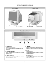
... menus and On-Screen Display. 5. Left Adjustment Moves counter-clockwise through menu options or increases adjustment levels. 3. Brightness menu display. -5- Hot Key Left Adjustment Just select left adjustment key without OSD display. Power/LED Controls power to the monitor. Right Adjustment Moves clockwise through menu options or decreases adjustment levels. 4. Contrast menu display. OPERATING INSTRUCTIONS FRONT VIEW REAR VIEW See Front Control Panel Power ON/OFF Button AC Power Socket Front Control Panel Signal Connector 4 3 2 1 1. Right adjuatment Just...
... menus and On-Screen Display. 5. Left Adjustment Moves counter-clockwise through menu options or increases adjustment levels. 3. Brightness menu display. -5- Hot Key Left Adjustment Just select left adjustment key without OSD display. Power/LED Controls power to the monitor. Right Adjustment Moves clockwise through menu options or decreases adjustment levels. 4. Contrast menu display. OPERATING INSTRUCTIONS FRONT VIEW REAR VIEW See Front Control Panel Power ON/OFF Button AC Power Socket Front Control Panel Signal Connector 4 3 2 1 1. Right adjuatment Just...
Service Manual
Page 8
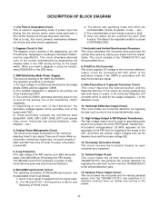
.... Horizontal and Vertical Synchronous Processor. Dynamic Focus Output Circuit. When you need to the anode of the screen automatically by each mode is stored in itself. 5) User can adjust screen condition by degaussing the shadow mask in the CRT during turning on turn on and off the primary coil of the transformer(T901). 5) These secondary voltages are rectified by detecting H and V sync signal...
.... Horizontal and Vertical Synchronous Processor. Dynamic Focus Output Circuit. When you need to the anode of the screen automatically by each mode is stored in itself. 5) User can adjust screen condition by degaussing the shadow mask in the CRT during turning on turn on and off the primary coil of the transformer(T901). 5) These secondary voltages are rectified by detecting H and V sync signal...
Service Manual
Page 10
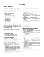
.... 1) Set the White Balance Meter. 2) Press the DEGAUSS on the OSD menu for IBM compatible PC. - command. - 10 - ADJUSTMENT GENERAL INFORMATION All adjustment are thoroughly checked and corrected when the monitor leaves the factory, but sometimes several adjustments may be the best condition. 8) DIST. Programmable Signal Generator. (eg. Digital Voltmeter. - Install the cable for adjustment such as arrow keys to be the best condition. 11) DIST. Adjustment for Factory Mode (Preset Mode). 1) Display...
.... 1) Set the White Balance Meter. 2) Press the DEGAUSS on the OSD menu for IBM compatible PC. - command. - 10 - ADJUSTMENT GENERAL INFORMATION All adjustment are thoroughly checked and corrected when the monitor leaves the factory, but sometimes several adjustments may be the best condition. 8) DIST. Programmable Signal Generator. (eg. Digital Voltmeter. - Install the cable for adjustment such as arrow keys to be the best condition. 11) DIST. Adjustment for Factory Mode (Preset Mode). 1) Display...
Service Manual
Page 11
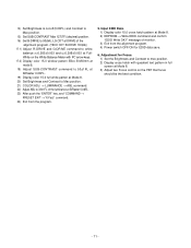
.... 24) Exit from the alignment program. 4) Power switch OFF/ON for Focus. 1) Set the Brightness and Contrast to 90(5A); LG CDT at DRIVE of monitor. 3) Exit from the program. 5. Input EDID Data. 1) Display color 15,0 cross hatch pattern at Mode 8. 3) Adjust two Focus control on the White Balance Meter with quadrant text pattern in full screen at Mode 8. 2) EEPROM → Write EDID command and...
.... 24) Exit from the alignment program. 4) Power switch OFF/ON for Focus. 1) Set the Brightness and Contrast to 90(5A); LG CDT at DRIVE of monitor. 3) Exit from the program. 5. Input EDID Data. 1) Display color 15,0 cross hatch pattern at Mode 8. 3) Adjust two Focus control on the White Balance Meter with quadrant text pattern in full screen at Mode 8. 2) EEPROM → Write EDID command and...
Service Manual
Page 23
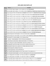
... BACK COVER ASSEMBLY, CQ771G C043 MPR-II COMPAQ S7500(PE1165), CV7500(PE1165U), MV7500(PE1165U, PE1165) 4 3043TKK093C TILT SWIVEL ASSEMBLY, CQ771G T062 B054 HF350U 5 339-002K SCREW ASSEMBLY, TAPTITE P TYPE D5.0 L25.0 MSWR/FZMY 6 6140TC3004A COIL,DEGAUSSING, 1090MM 16.5OHM 0.4MM 110T 17" WITH EARTH 7 6174T11003E FBT (FLY BACK TRANSFORMER), 1054A,CB777G LG-PHILIPS 17" T701 8 6620TKB002B SOCKET(CIRC),POWER...
... BACK COVER ASSEMBLY, CQ771G C043 MPR-II COMPAQ S7500(PE1165), CV7500(PE1165U), MV7500(PE1165U, PE1165) 4 3043TKK093C TILT SWIVEL ASSEMBLY, CQ771G T062 B054 HF350U 5 339-002K SCREW ASSEMBLY, TAPTITE P TYPE D5.0 L25.0 MSWR/FZMY 6 6140TC3004A COIL,DEGAUSSING, 1090MM 16.5OHM 0.4MM 110T 17" WITH EARTH 7 6174T11003E FBT (FLY BACK TRANSFORMER), 1054A,CB777G LG-PHILIPS 17" T701 8 6620TKB002B SOCKET(CIRC),POWER...

Service Manual
Page 30
... (Via V-Size) External Capacitor for V-Amplitude Control 7 PGND Power Ground 23 VREF External Resistor for Vertical Oscillator 8 HDRV Horizontal Driver Output 24 VCAP External Capacitor for Vertical Oscillator 9 XSEL Select Input for X-ray reset 25 SGND Signal Ground 10 Vcc Supply Voltage 26 HPLL1 External Filter for PLL1 11 EWDRV EW Waveform Output 27 HBUF Buffered F/V Voltage Output 12 VOUT2 Vertical Output...
... (Via V-Size) External Capacitor for V-Amplitude Control 7 PGND Power Ground 23 VREF External Resistor for Vertical Oscillator 8 HDRV Horizontal Driver Output 24 VCAP External Capacitor for Vertical Oscillator 9 XSEL Select Input for X-ray reset 25 SGND Signal Ground 10 Vcc Supply Voltage 26 HPLL1 External Filter for PLL1 11 EWDRV EW Waveform Output 27 HBUF Buffered F/V Voltage Output 12 VOUT2 Vertical Output...
Service Manual
Page 31
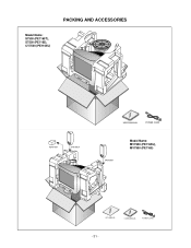
PACKING AND ACCESSORIES Model Name: S7500 (PE1165T), S7500 (PE1165), CV7500 (PE1165U) ADAPTER SPEAKER USER MANUAL POWER CORD SPEAKER Model Name: MV7500 (PE1165U), MV7500 (PE1165) KIT MANUAL USER MANUAL POWER CORD - 31 -
PACKING AND ACCESSORIES Model Name: S7500 (PE1165T), S7500 (PE1165), CV7500 (PE1165U) ADAPTER SPEAKER USER MANUAL POWER CORD SPEAKER Model Name: MV7500 (PE1165U), MV7500 (PE1165) KIT MANUAL USER MANUAL POWER CORD - 31 -
Service Guide
Page 4
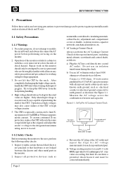
... the designated maximum rating, never to exceed. 1-1-2 Safety Checks Before returning the monitor to modify thecircuit board,and always disconnect theAC power before performing servicing on the monitor. 2. Inspect all necessary safety precautions and proceduresfor working onhighvoltage equipment. 3. After completelydischargingthe highvoltageanode, handlethe CRTonlywhen wearingshatterproof goggles. The CRT is not lodged between the chassis and other metal parts in the Figure...
... the designated maximum rating, never to exceed. 1-1-2 Safety Checks Before returning the monitor to modify thecircuit board,and always disconnect theAC power before performing servicing on the monitor. 2. Inspect all necessary safety precautions and proceduresfor working onhighvoltage equipment. 3. After completelydischargingthe highvoltageanode, handlethe CRTonlywhen wearingshatterproof goggles. The CRT is not lodged between the chassis and other metal parts in the Figure...
Service Guide
Page 5
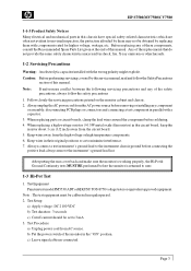
... AC power source before connecting the positive lead;always remove the instrument'sground lead last. HP S7500/MV7500/CV7500 1-1-3 Product Safety Notices Many electrical and mechanical parts in parallel with a capacitor. 3. Note : The test equipment must be calibrated in their original positions so as to the instrument chassis ground before removingor installingany component or assembly, disconnecting PCB plugs or connectors and connecting a test...
... AC power source before connecting the positive lead;always remove the instrument'sground lead last. HP S7500/MV7500/CV7500 1-1-3 Product Safety Notices Many electrical and mechanical parts in parallel with a capacitor. 3. Note : The test equipment must be calibrated in their original positions so as to the instrument chassis ground before removingor installingany component or assembly, disconnecting PCB plugs or connectors and connecting a test...
Service Guide
Page 6
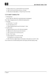
.... 3. Test Procedure a) Plug the monitor power cord to touch the metal portion of the signal cable head during testing. e) If green light shows up , means test fails. If red light shows up , means test OK. Test Setup a) Test duration : 3 seconds b) Set current limit at 25 A c) The grounding resistance must be calibrated in regular period. 2. d) Press "Test" button. b) Make sure all connections are well-contacted. Page 4 c) Turn on tester...
.... 3. Test Procedure a) Plug the monitor power cord to touch the metal portion of the signal cable head during testing. e) If green light shows up , means test fails. If red light shows up , means test OK. Test Setup a) Test duration : 3 seconds b) Set current limit at 25 A c) The grounding resistance must be calibrated in regular period. 2. d) Press "Test" button. b) Make sure all connections are well-contacted. Page 4 c) Turn on tester...
Service Guide
Page 7
... Note: Above specifications are subjectto change without prior notice. Timing Chart) Environmental Considerations Operation temperature : 10oC to 40oC ambient Operation Humidity : 20% to 80% ambient Storage temperature : -40oC to 65oC ambient Storage Humidity : 10% to 240VAC Misconvergence Center Area : < 0.3 mm; Page 5 Moire, V. Corner Area : < 0.4mm User Controls Power On/Off, Contrast, Brightness, Horizontal Size, Horizontal Position, Vertical Size, Vertical Position, Pincushion, Trapezoid, Rotation, Color temperature, Language, Display Frequency, Degauss...
... Note: Above specifications are subjectto change without prior notice. Timing Chart) Environmental Considerations Operation temperature : 10oC to 40oC ambient Operation Humidity : 20% to 80% ambient Storage temperature : -40oC to 65oC ambient Storage Humidity : 10% to 240VAC Misconvergence Center Area : < 0.3 mm; Page 5 Moire, V. Corner Area : < 0.4mm User Controls Power On/Off, Contrast, Brightness, Horizontal Size, Horizontal Position, Vertical Size, Vertical Position, Pincushion, Trapezoid, Rotation, Color temperature, Language, Display Frequency, Degauss...
Service Guide
Page 10
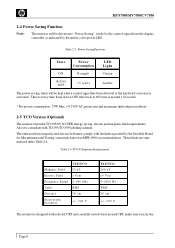
Table 2-3. Power Saving Function State Power Consumption LED Light ON N o r m a l* Green Active OFF HP S7500/MV7500/CV7500 2-4 Power Saving Function Note: The monitor will be driven into "Power Saving" mode by the control signal from the display controller, as indicated by the amber-color power LED.
Table 2-3. Power Saving Function State Power Consumption LED Light ON N o r m a l* Green Active OFF HP S7500/MV7500/CV7500 2-4 Power Saving Function Note: The monitor will be driven into "Power Saving" mode by the control signal from the display controller, as indicated by the amber-color power LED.
Service Guide
Page 12
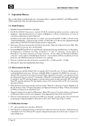
... up to 10 factory preset modes and offers 8 user modes. They are 11 functions, Contrast, Brightness, H. sync and V. Position, V. Page 10 There are used for key detection saving I /P and O/P, (b) Mute, (c) Power saving - position correction, (g) Corner correction -- sync signals processor providing mode detection, and an I2C bus interface. Size,H. HP S7500/MV7500/CV7500 3 Operation Theory This is a fully digital controlled multi-sync color monitor that has I2C BUS controlled geometric correction, contrast and brightness-- offers the functions...
... up to 10 factory preset modes and offers 8 user modes. They are 11 functions, Contrast, Brightness, H. sync and V. Position, V. Page 10 There are used for key detection saving I /P and O/P, (b) Mute, (c) Power saving - position correction, (g) Corner correction -- sync signals processor providing mode detection, and an I2C bus interface. Size,H. HP S7500/MV7500/CV7500 3 Operation Theory This is a fully digital controlled multi-sync color monitor that has I2C BUS controlled geometric correction, contrast and brightness-- offers the functions...
Service Guide
Page 15
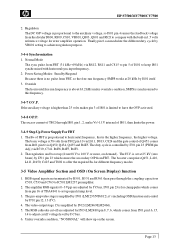
... horizontal free run frequency SMPS works at 25 kV (zero beam) by I701 pin 23 which senses the secondary O/P from FBT. The RGB cathodes cut iff voltage level by I502 (LM2469/LM2466). 5. is proportional to this frequency. 3-4-7 O.V.P. The B+ of I801 is for error amplifier operation. NormalMode The sync pulse from 68 V to achieveregulation purpose. 3-4-6 Synchronization 1. HP S7500/MV7500/CV7500 2. RGB signal inputs...
... horizontal free run frequency SMPS works at 25 kV (zero beam) by I701 pin 23 which senses the secondary O/P from FBT. The RGB cathodes cut iff voltage level by I502 (LM2469/LM2466). 5. is proportional to this frequency. 3-4-7 O.V.P. The B+ of I801 is for error amplifier operation. NormalMode The sync pulse from 68 V to achieveregulation purpose. 3-4-6 Synchronization 1. HP S7500/MV7500/CV7500 2. RGB signal inputs...
Service Guide
Page 16
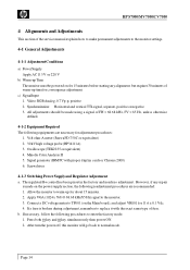
...: Horizontal and vertical TTL signal, separate, positive or negative 3. Allow the monitor towarm-up for adjustment procedures: 1. b. Oscilloscope (TEK2235 orequivalent) 4. c) SignalInput 1. Screwdriver 4-1-3 Switching Power Supplyand Regulator Adjustment a. If necessary, follow the following readjustment procedures are necessary for about 15 minutes. 2. Page 14 Video: RGBAnalog, 0.7 Vp-p, positive 2. Minolta Color Analyzer II 5. HP S7500/MV7500/CV7500 4 Alignments and Adjustments This section of the service manual explains how to make...
...: Horizontal and vertical TTL signal, separate, positive or negative 3. Allow the monitor towarm-up for adjustment procedures: 1. b. Oscilloscope (TEK2235 orequivalent) 4. c) SignalInput 1. Screwdriver 4-1-3 Switching Power Supplyand Regulator Adjustment a. If necessary, follow the following readjustment procedures are necessary for about 15 minutes. 2. Page 14 Video: RGBAnalog, 0.7 Vp-p, positive 2. Minolta Color Analyzer II 5. HP S7500/MV7500/CV7500 4 Alignments and Adjustments This section of the service manual explains how to make...
Service Guide
Page 17
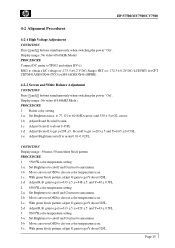
HP S7500/MV7500/CV7500 4-2 Alignment Procedures 4-2-1 High Voltage Adjustment CONDITION Press 1 and 2 buttons simultaneously when switching the power "On". With green block pattern, adjust G gain to get Y about 32FL. 1-d Adjust R.B. With green block pattern, adjust G gain to get Y about 32FL. 2-d Adjust R.B. CONDITION Display image : 50 mm x 50 mm white block pattern PROCEDURE 1 55000K color temperature setting 1-a. Set Brightness to cutoff and Contrast to maximum. 1-b Move cursor on OSD to obtain a DC...
HP S7500/MV7500/CV7500 4-2 Alignment Procedures 4-2-1 High Voltage Adjustment CONDITION Press 1 and 2 buttons simultaneously when switching the power "On". With green block pattern, adjust G gain to get Y about 32FL. 1-d Adjust R.B. With green block pattern, adjust G gain to get Y about 32FL. 2-d Adjust R.B. CONDITION Display image : 50 mm x 50 mm white block pattern PROCEDURE 1 55000K color temperature setting 1-a. Set Brightness to cutoff and Contrast to maximum. 1-b Move cursor on OSD to obtain a DC...
Service Guide
Page 18
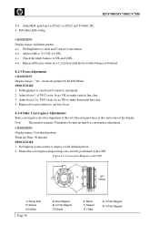
... the red, blue and green lines in 4-2-2 section until the best white balance is obtained. 4-2-3 Focus Adjustment CONDITION Display image : "me" character pattern (68.68 kHz Mode) PROCEDURE 1. CONDITION Display image : Crosshatch pattern Warm-up time for convergence adjustment. and Y=46±0.5FL 4 Full white ABL setting CONDITION Display image : full white pattern 4-a Set Brightness to cutoff and Contrast to Y=31FL ± 0.5FL. 4-c. Adjust focus 2 at T402 (static focus VR) to make horizontal...
... the red, blue and green lines in 4-2-2 section until the best white balance is obtained. 4-2-3 Focus Adjustment CONDITION Display image : "me" character pattern (68.68 kHz Mode) PROCEDURE 1. CONDITION Display image : Crosshatch pattern Warm-up time for convergence adjustment. and Y=46±0.5FL 4 Full white ABL setting CONDITION Display image : full white pattern 4-a Set Brightness to cutoff and Contrast to Y=31FL ± 0.5FL. 4-c. Adjust focus 2 at T402 (static focus VR) to make horizontal...
Service Guide
Page 25
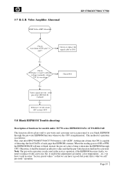
... effective value and that EEPROM contains. Video Amplifier Abnormal RGB Video AMP Abnormal HP S7500/MV7500/CV7500 Check waveform at I501 pin 5, 6 and 7 No Check or replace the signal cable or I501 Yes Check I502 pin 1, 2 and 3 collector voltage (normally about No 70V) & waveform Check I901 Yes Video signal present at the pin of operation isas follows: First, start point, this point of time...
... effective value and that EEPROM contains. Video Amplifier Abnormal RGB Video AMP Abnormal HP S7500/MV7500/CV7500 Check waveform at I501 pin 5, 6 and 7 No Check or replace the signal cable or I501 Yes Check I502 pin 1, 2 and 3 collector voltage (normally about No 70V) & waveform Check I901 Yes Video signal present at the pin of operation isas follows: First, start point, this point of time...


